MOTOR WIRING
1. Before working on any electrical connections be sure that the power is turned o.
2. All wiring must conform to local, state and/or national codes.
3. All wiring must conform to wiring diagram on the motor nameplate or on the back of the terminal cover.
4. Incoming line voltage must be within 10% of the nameplate voltage.
5. A solid copper bonding conductor no smaller than No. 8 AWG should be connected from the wire connector
on the motor to all metal parts of the spa or hot tub structure, and, to all electrical equipment, metal conduit,
and metal piping within ve feet of the inside walls of a swimming pool, spa or hot tub when the motor is
installed within ve feet of the inside walls of the spa or hot tub.
6. DO NOT ground to a gas supply line.
7. Ground motor prior to connecting to electrical power.
8. Improper grounding can cause serious injury and damage to the motor, voiding the warranty.
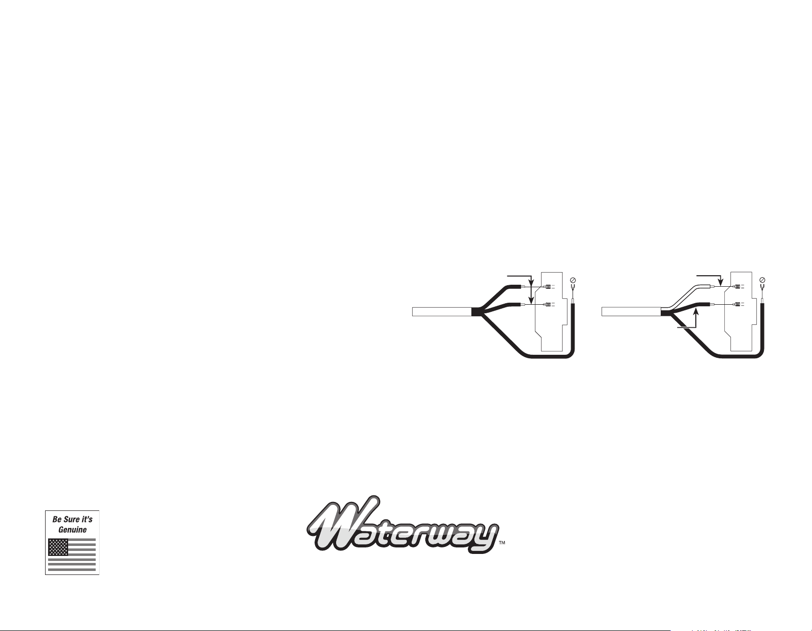
230V
1-Speed
Black
(Power)
Green (Ground)
IRON MIGHT PUMP INSTRUCTIONS
ALL ELECTRICAL INSTALLATIONS SHOULD BE PERFORMED BY QUALIFIED ELECTRICIANS
• WARNING: Risk of electrical shock. Connect only to a Ground-Type Receptacle protected by a Ground-Fault Circuit
Interrupter (GFCI). Potential risk of re, electric shock or injury to person if misused. Do not install within an outer
enclosure or beneath the skirt of the spa unless so marked.
• WARNING:To reduce the risk of injury, do not permit children to use this product unless they are closely
supervised at all times.
• CAUTION: This pump is for use with permanently installed pools and may also be used with hot tubs and spas
if so marked. Do not use with storable pools. A permanently installed pool is constructed in or on the ground
or in a building such that it cannot be readily disassembled for storage. A storable pool is constructed so that it
may be readily disassembled for storage and reassembled to its original integrity.
INSTALLATION INSTRUCTIONS
LOCATION: Place pump on level surface. Pump must be installed below water surface. Shut o valves should be
installed on both the inlet and outlet of the pump for future maintenance. Installation area should be clear of any
direct water and have adequate oor drainage. Pump should be protected from excessive moisture. Allow access
area large enough to service both pump and plumbing.
The inlet and outlet haveWaterway male union threads. UseWaterway tailpiece assemblies for best connection.
These unions allow the pump to be removed for service without disturbing the plumbing.
HAND TIGHTEN UNIONS ONLY! DO NOT USE A WRENCH OR ANY ADHESIVES OR SOLVENTS!
DO NOT use pipe sealant. Use only Teon tape or other sealing compounds approved for use with plastic. Some
pipe sealants not approved for use with plastic will cause stress cracking of plastic parts. New installations often
require plumbing inspections. This inspection is usually conducted using city water pressure. A pressure regulator
should be used when preforming this test and should not exceed 40 PSI during the pressure test.When the lter
and pump are under pressure, insure that all air is removed from the system. Extreme care must be taken during the
pressure test. FAILURE TO FOLLOW THESE INSTRUCTIONS EXPLICITLY CAN RESULT IN PERSONAL INJURY AND
WARRANTIES WILL BE VOIDED.
IMPORTANT SAFETY INSTRUCTIONS & WARNINGS • SAVE THESE INSTRUCTIONS • PLEASE READ AND FOLLOW ALL INSTRUCTIONS
2200EastSturgisRoad,Oxnard,CA93030•Ph.(805)981-0262•Fax(805)981-9403
www.waterwayplastics.com•waterway@waterwayplastics.com 810-0231.0410
© 2010 Waterway Plastics
WARRANTY
The Iron Might pump will receive a limited warranty from any defect in material or workmanship of one year from the date of manufacture.This includes the motor,
but not the motor seal. Products that fail or become defective during the warranty period, except as a result of improper installation, bad water chemistry, accidents
or negligence on behalf of the owner, freezing, earthquakes, re, oods or other acts of nature, shall be repaired or replaced atWaterway’s option without charge
to the owner. This process will be completed within 90 days of receipt of the defective product barring delays caused by the acquisition of component parts not
manufactured at our facility. To obtain warranty replacements or repair, defective products should be returned (transportation paid) to the place of purchase, or to
Waterway. It should include a description of the defect and the circumstances surrounding the incident or problem.Warranty begins on the date of manufacture.
Waterway shall not be responsible for cartage, removal and/or reinstallation labor, or any other such costs incurred in obtaining warranty replacementsThis warranty
gives you specic legal rights. You may also have other rights which vary from state to state.
White
(Common)
115V
1-Speed
Black (Power)
Green (Ground)
1
2
Ensure wiring circuit agrees with diagram and leads are securely tight.


