The Hozelock Cyprio Cascade pumps are
electrically operated and designed for use in
garden ponds and waterfalls. The pumps do
not use oil or grease for lubrication and can be
used safely in ponds containing fish or plants.
The motor consists of a sealed stator and
watercooled rotor. All electrical components
are isolated from the water.
WARNING: SAFETY AND
ELECTRICAL CONNECTIONS
1. The pump is supplied complete with 10m of
3-core electric cable, which is permanently
connected and sealed to the motor.
Under no circumstances should any repair
be made to the cable.
THIS PRODUCT IS DESIGNED TO BE
PERMANENTLY WIRED TO THE MAINS
SUPPLY IN A DRY WEATHERPROOF
ENCLOSURE THROUGH A DOUBLE-POLE
SWITCHEDFUSED SPUR - WITH A MINIMUM
CONTACT GAP OF 3mm. (DISCONNECTOR)
TO BS 3676 - FITTED WITH A 3 AMP FUSE.
2. If an extension cable is required, this should
be connected to the end of the pump cable
using a weather-proof cable connector. The
joint must be positioned outside the pond
in a suitably dry housing.
The extension cable should be of 3-core,
0.75mm2Polychloroprene rubber insulated
cable (ref HO5 RN-F) and connected to the
mains supply with a 3 amp fuse. IT IS
ESSENTIAL THAT THE PUMP IS CORRECTLY
EARTHED AND THAT ALL CONNECTIONS
ARE SECURELY MADE USING THE
FOLLOWING CODE.
Brown - Live
Blue - Neutral
Green/Yellow- Earth
The BROWN lead should be connected to
the LIVE terminal, which may be marked
with an ‘L’ or coloured brown or red.
The BLUE lead should be connected to the
NEUTRAL terminal, which may be marked
with an ‘N’ or coloured blue or black.
The GREEN/YELLOW lead should be
connected to the EARTH terminal which
may be marked with an ‘E’ or coloured
green or green/yellow.
3. The pump cable (and extension cable),
should be positioned and adequately
protected against damage especially where
contact with gardening equipment (lawn
mowers; forks etc), children and domestic
animals may occur.
4. A 10mA or 30mA Residual Current Device
(RCD) MUST be fitted to the mains supply.
5. For permanent installations to the mains
supply, it is necessary to conform to the
regulations of the National and Local
wiring regulations which would include the
use of plastic or metal conduit to protect
the cable.
6. The supply cord fitted to this pump can
only be replaced using special tools. In the
event of the cable becoming damaged
return the pump to Hozelock Cyprio
Consumer services at the address shown.
7. CONSULT A QUALIFIED ELECTRICIAN OR
LOCAL ELECTRICITY AUTHORITY, IF IN ANY
DOUBT ABOUT WIRING TO THE MAINS
SUPPLY.
IMPORTANT
1. ALWAYS DISCONNECT THE MAINS
ELECTRICITY SUPPLY WHILST THE
EQUIPMENT IS BEING INSTALLED,
REPAIRED, MAINTAINED, OR HANDLED.
2. Do not use the supply cable to lift the
pump, as this may cause damage.
3. Do not operate or leave the pump in
freezing conditions.
4. Do not allow the pump to run in dry
conditions.
5. Check that the voltage marked on the
pump corresponds to the Mains Supply.
6. We recommend looping a lifting cord
through the pump handle when the pump
is installed in deep water.
7. DO NOT OPERATE THIS PUMP WITHOUT A
METHOD OF FILTRATION ATTACHED.
USING THE PUMP WITHOUT A FILTER MAY
INVALIDATE YOUR WARRANTY.
If the filter supplied is not suitable for your
application, Hozelock Cyprio can supply an
additional range of filters which may suit
your needs. For more details call Hozelock
Cyprio Helpline on 0870 850 1959.
PUMP INSTALLATION
ATTENTION: This product is not
suitable for water temperatures
above 35ºC
Position
Construct a solid and level platform on which
to place the pump. For installations using the
fountain, the top of the platform should be
230mm (9 inches) below the water level.
A typical installation is shown for guidance in
fig.1.
FOUNTAIN ONLY
1. Place the pump next to the pond and route
the cable back to the mains supply.
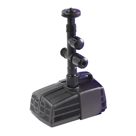
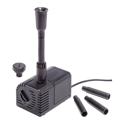
2. Assemble the ‘T’ piece Adaptor and 3-Tier
Fountain Head on the pump and place into
position within the pond.
3. The fountain height can be regulated by
rotating the Flow Adjuster Screw.
4. If required the 2-Tier Fountain Head can be
used to achieve an alternative and higher
display pattern.
FOUNTAIN AND WATERFALL
1. Position the pump as previously described.
2. Remove the Blanking Cap and connect a
suitable length of 25mm (1”) bore hose by
pushing directly over the threaded outlet
boss.
NOTE: Small diameter hoses 13mm (1/2”)
and 19mm (3/4”) can be used by fitting the
outlet adaptor into the outlet boss. If small
diameter hose is used the flow will be
reduced.
3. The combination of waterfall and fountain
will reduce the fountain height that can be
achieved.
4. Route the hose back to the waterfall.
WATERFALL ONLY
1. For best results fit a suitable length of
25mm (1”) bore hose directly on to the
outlet of the pump. In some installations
the water may not be deep enough and
could cause the hose to become exposed
above the pond surface. In this case fit the
‘T’ Piece Adaptor, remove the Blanking Cap
and use the outlet boss with the Adjuster
Screw fully tightened.
Cascade 5500, 7000
INSTALLATION AND OPERATING INSTRUCTIONS.
READ INSTRUCTIONS CAREFULLY BEFORE ATTEMPTING INSTALLATION.
3350
3360
Attention:
AUTOMATIC CUT-OUT. To help
ensure your pump’s long life and
prevent damage, it is fitted with
automatic thermal overload
protection. This switches off the
pump if it overheats. If this occurs,
switch off the power at the mains
supply to the pump. Check for the
cause. Usually it will be debris
blocking the inlets of the pump or
obstructing the impeller. Remove
the obstruction and wait 15minutes
for the pump to cool down and
automatically reset. Then switch on
the pump again.
NOTE:
YOU MUST SWITCH OFF THE MAINS
SUPPLY BEFORE THE PUMP WILL
RESET.
From 1st January 2005 installing
this product in the garden is
classed as 'notifiable' in the revised
Building Regulations for England
and Wales. The Regulations now
require you to tell your local
authority building control
department that you intend to
install this product before
installation. Your local authority
will let you know how you can get
your installation approved.
Cascade 5500-Hmax 4.9m
Cascade 7000-Hmax 5.5m
