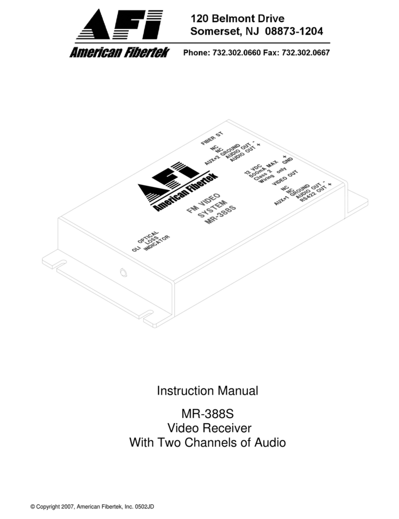
Watkins Johnson WJ-8711A Instruction manual

TheWJ-8711Aisafullysynthesized,general-purposeHF
receiverforsurveillanceandmonitoringofRFcommunica-
tions from 5 kHz to 30 MHz with 1-Hz tuning resolution.
Bycombininganaloganddigitalsignalprocessing(DSP),
theWJ-8711Aachieveshighperformanceatlowcost.
Functionssuchasnoiseblanking,IFfiltering,AGC,
demodulation,BeatFrequencyOscillator(BFO)and
passbandtuningareaccomplishedthroughtheuseofDSP
techniques.Filterswithsuperioramplitudeandgroupdelay
characteristicsareachievedwithdigitalstabilityand
repeatability.StandardselectableIFbandwidths(66inall)
areshowninTable1.AvailabledetectionmodesareAM,
SAM,FM,CW,USB,LSBandISB.AtunableBFOis
adjustablein10-Hzstepsovera+8000Hzrange,and
passbandtuningisavailabletofurtherenhancetherecep-
tionofCWsignals.Gaincontrolisaccomplishedmanually
orautomatically,withfast,medium,andslowAGCmodes
available.Thesquelchthresholdisadjustablefrom0to
-135 dBm, or it can be disabled. Enabling the noise blank-
ingfeatureeffectivelyeliminatestheadverseeffectsof
impulsivenoise.
Inadditiontofixed-frequencytuning,theWJ-8711A
providesfast,flexiblescanning.Threescanmodesare
available:channelscan,F1-F2scanandF1-F2scanwith
lockouts.For allscan modes,the dwelltimecanbesetfrom
0.5to20 secondsorinfinite.Inchannelscanmode,100
programmablememorychannelsareavailable.Sectorsof
memorycanbespecifiedforindividualchannelscans,
Digital HF Receiver
WJ-8711A
Features
❏Frequencycoveragefrom5kHzto30 MHzin
1-Hzsteps
❏Highdynamicrange:+30dBm3rd-order
intercepttypical
❏Digitalfilteringprovides66IFbandwidthsup
to 16 kHz with exceptional shape factors
❏AM,SAM,FM, CW,USB,LSB&ISBDetec-
tionModesStandard
❏Fast,flexiblescanningwith100memory
channels
❏LargereadableLEDdisplays&user-friendly
controls
❏3variableAGCdecaysettings
❏Noiseblanking&passbandtuning
❏TunableIFNotchFilter
❏Internalswitchablepreamplifier&attenuator
❏Standardremoteinterface(optional
MultidropRS-232,RS-485,RS-422,CSMA,
orIEEE-488)
❏Built-inselftest
❏OptionalSuboctavePreselector
❏OptionalDigitalDataOutput
HEIGHT 5.25 in (13.36 cm) DEPTH 20.0 in (50.80 cm)
WIDTH 19.0 in (48.26 cm) WEIGHT 15 lbs (6.78 kg)
Specification subject to change without notice.
Printed in the U.S.A.
Technical Data WATKINS-JOHNSON
May 1996
WATKINS-JOHNSONCOMPANY
700 Quince Orchard Road, Gaithersburg, Maryland 20878-1794
Phone: (800) WJHELPS or +(301) 948-7550
All International sales of WJ equipment are subject to USA
export license approval.
This material provides up-to-date general information on
productperformanceanduse. Itisnotcontractualinnature,
nor does it provide warranty of any kind.

2
WJ-8711A
56 113 225 450 900 1800 3600 7200 14400
63 125 250 500 1000 2000 4000 8000 16000
69 138 275 550 1100 2200 4400 8800
75 150 300 600 1200 2400 4800 9600
81 163 325 650 1300 2600 5200 10400
88 175 350 700 1400 2800 5600 11200
94 188 375 750 1500 3000 6000 12000
100 200 400 800 1600 3200 6400 12800
allowingthesubdivisionofavailablememoryinto
multiplesearchscenarios.Theoperatorcanspecify
certainchannelstobeskippedwithouthavingto
deletethemfrommemory.Memorychannelscanalso
besingle-steppedmanually.InbothF1-F2scan
modes,thestepsizeisuser-selectablefrom 1Hz to25
kHz.Upto100independentfrequencylockoutscan
bestored.
AnoperatorcancontroltheWJ-8711Alocallyviathe
frontpanelorremotelyviatheserialinterface.
Measuring5.25x19inches,(13.34x48.26cm),the
microprocessor-controlledfrontpanelprovidesauser-
friendlyoperatorinterfacewithdedicated,logically
arrangedcontrolsandlarge,easy-to-readLED
displays.Figure1illustratestheorganizationofthe
frontpanelandhighlightssomeofthefeatures
availabletothelocaloperator.
AmajorityoftheWJ-8711Aoperator-selectable
parametersarecontrollableandaccessibleviaan
RS-232remoteinterface. RS-485,RS-422,and
IEEE-488interfacesareoptional.
Allreceiverinputsandoutputsareavailableonthe
rearpanelof the unit withtheexception of the front-
panel-mountedheadphonejack.Theantennaand
externalreferenceinputs,aswellasthesignalmonitor
andpredetectedIFoutputs,areavailableonBNC
connectors.Speakeranddual-balancedlineaudio
outputsareavailableonaterminalstripalongwith
dc-coupledaudio,RSSIandsquelchoutputs,anda
mutecontrolinput.TheRS-232interfaceisavailable
ona25-pinD-shellconnector.
AnoperatorcanusetheWJ-8711Aasatabletop
receiverormountedinastandard19-inch(48.26cm)
equipmentrackoccupying5.25inches(13.34cm)of
verticalrackspace.Theinternalpowersupplyaccepts
97 to 253 Vac (47 to 63 Hz) line power and automati-
callyadjuststo theinputlinevoltage.Totalpower
consumptionoftheunitislessthan35watts.
Atunable IFnotchallows anoperatorto tunea
DigitalNotchFilterthroughtheselectedIFBand-
width(IFBW),inordertoeliminateundesiredsignals
withintheIFPassband. Typicalnotch3-dBband-
width is 10 to 20 percent of the selected IFBW and
provides50-dBofrejection(typical). Thenotchfilter
isa nonlinearphase IIRFilter andshould notbe used
whenflatgroup-delayresponseisrequired.Not
availableinCWdetectionmode.
Options
ThestandardDigitalHFReceiverisavailableina
varityofmechanicalconfigurations. Continuous
productimprovementshavealsoproducedsignificant
enhancementsandawidearrayofoptions. See
separateWJ-871YOptionsMatrixdatasheetfor
details.
The 900 through 3200 Hz bandwidths are available in SSB detection mode.
IF Filters (Nominal 3 dB Bandwidth in Hz)

3
WJ-8711A
I/O Function Type
Input Antenna BNC
External Reference BNC
Power IEC 3-pin
Mute Terminal Block
Output Signal Monitor BNC
IF BNC
Line Audio Output A & B Terminal Blocks
Speaker Terminal Block
DC-coupled Audio Terminal Block
Squelch Terminal Block
Headphone Standard 0.25-in (0.63 cm) stereo jack
Received Signal Strength Terminal Block
Indicator
Bidirectional CSMA Remote Interface 0.12-in (0.30 cm) miniature stereo jack
RS-232 Remote Interface 25-pin female D-shell
Input/Output Connectors
9
6
3
8
5
2
7
4
RFINPUT
FREQUENCY
PHONES SPEAKER
GAIN
USB
BOTH
LS B
PRE A MP
NORM
ATTN
CE
WATKINS-JOHNSON
POWER
0
1
MHz
WJ-87 11 HFRECEIV ER
MHz
kHz
TUNE
REMOTE
MANU AL
LOCK
STEP
TUNE
CHAN NEL
EXEC U TE
0
-20
-40
-60
-80
-100
-110
-120
GAITHERS BU R GMDUS A
REMOTECONTROL
BY RS-232 ORCSMA/CD
DEDICATEDCONTROLS
FORSCANNINGAND
MEMORYFUNCTIONS
ILLUMINATEDSIGNAL
STRENGTHMETER
CALIBRATEDINdBm
MOSTFREQUENTLYUSED
FUNCTIONSCONVENIENTLY
NEARTHETUNINGKNOB
PRECISION
DSP NOISE BLANKER
LARGELEDFREQUENCY
READOUTTO1HzRESOLUTION
ERGONOMICALLYDESIGNED
KEYPADAND TUNINGKNOBFOR
EASY FREQUENCYENTRY
ACCESS TOADDITIONAL
FEATURES LIKE
PASSBAND TUNING
AND BUILT-INTEST
SELECTABLE
RFINPUTPRE-AMP
ORATTENUATION
INDEPENDENTSPEAKER
AND HEADPHONECONTROLS
AGCBFOBLANKER
IFBWDETMODE S QUELC H
DN UP
+/-ZERO
SPECIAL
FUNCTION
MEMORY/SCAN
FREQUENCY
w/LOCK
F1F2
CHANNEL
F1F2
SCAN
TYPE
D N
UP
CLEAR
CHANNEL
CHANNEL
CHANNEL
P A US E
SCAN
SETUP
STOREINCLUDE
LOCKOUTSKIP
DWEL L
STE P
SIZE
CHAN NEL
VIEW
SCAN
HzmSec
dBm
kHz
CALIBRATED
SQUELCH LEVEL
WPG100
WJ-8711A Front Panel Features

4
WJ-8711A
Functional Description
Figure2illustrateshowtheWJ-8711Aisdividedinto
fourfunctionalsubsystems:RF,DSP,IF/Audio
OutputandControl.Figure3providesafunctional
block diagram of the RF Subsystem. The 5 kHz to
30 MHz RF signal is applied to the receiver’s antenna
input,lowpassfiltered,andthenamplified,attenuated
orroutedtothenormalthrough-pathbasedonuser
selection.Thesignalisthen mixedwiththefirstlocal
oscillator (LO), which tunes from 40.455 MHz to
70.455MHzin1-kHzsteps,toproduce afirst IFof
40.455MHz.ThefirstIFfilterlimitsthebandwidths
ofthesignaltoapproximately30kHzbeforemixing
itwiththe40-MHzsecondLOto producea secondIF
at 455 kHz. A sample of this second IF is provided on
arear panelfor connectiontoa signaldisplay unit.
AfterpassingthroughthesecondIFfilter,thesignal
ismixedwiththe430-kHz thirdLOtoproducethe
third IF centered at 25 kHz.
AllLOsarederivedfromaninternal10-MHz
oscillatorthatcanbelockedtoanexternalreference
inputof 1,2,5 or 10MHz. The WJ-8711Aauto-
maticallysensesandswitchestotheexternalrefer-
enceuponapplicationofsignal.Allcriticaltiming
signalsusedintheDSPandIF/AudioOutput
Subsystemsarealsoderivedfromthisreference.
TheDSPSubsystemperformsthemajorityofthe
receiver'ssignalprocessingfunctions.ThethirdIF
signalfromtheRFSubsystemisdigitizedto16bits
of resolution at a sampling rate of 100 kHz. This
digitizedIFsignalisappliedtoaprogrammable
DSPchipthatperforms the followingfunctions
FRONT
PANEL
ASSEMBLY
HEADPHONE
OUTPUT
SPEAKEROUTPUT
LINEAUDIOA
LINEAUDIOB
DC-AUDIO
IFOUTPUT
SIGNALMONITOR
OUTPUT
MUTE
SQUELCH OUT
RSSI
POWER
SUPPLY
SELECTABLE
REMOTECONTROL
CONTROL
SUBSYSTEM
RF
SUBSYSTEMDSP
SUBSYSTEM
IF/AUDIO
OUTPUT
SUBSYSTEM
RFGAIN
CONTROL
3RD IF
DC POWER
ACPOWER
EXTERNAL
REFERENCE
1,2,5,10 MHz
ANTENNA
INPUTDATA
TIMING
&CONTROL
AUDIO
VOLUME
CONTROL
HEADPHONE
AUDIO
PRESELECTOR
(OPTIONAL)
FRONT
PANEL
CONTROL
INTERNAL
SPEAKER
(OPTIONAL)
RS-232
CSMA
WJ-8711A Functional Block Diagram

5
WJ-8711A
basedonoperatorselectionofthereceiver’s
parameters:
●Noiseblanking
●Finetuningto1-Hzresolution
●IFfiltering
●Gaincontrol(AGCFast,AGCMedium,AGC
Slow,orManual)
●Signalstrengthandsquelchfunctions
●SignaldemodulationandBFO
●Generationofamultiplexeddigitaldatastream
containing1or2demodulatedaudiochannelsand
apost-filteredIFsignal
TheIF/audiooutputsubsystemperformstheanalog
reconstructionoftheIFandaudiosignalsprovidedby
theDSPsubsystemindigitalform.Theanalogaudio
signalsareroutedthroughtwodistinctsignalpathsto
accommodateISBdetection mode.In all other
detectionmodes,bothpathscontainidenticalaudio
signals.Thesetwoaudiopathsareprocessedto
providea2-channelheadphoneoutput,twobalanced
600-ohmlineaudiooutputsandan8-ohmspeaker
outputcontainingoneorbothaudiochannelsinISB
mode.Afteranalogreconstruction,theIFsignalis
upconvertedto455kHz,passedthroughabandpass
roofingfiltertoremovemixerproducts,bufferedand
routedtotherearpanelIFoutputconnector.
Themicroprocessor-basedcontrolsubsystemper-
formsthereceiver’sinternalcontrol,actsasan
interfacewiththefrontpanel,andprovidesaremote
controlfunctionthrougheithertheRS-232orthe
optionalRS-485,RS-422,orIEEE-488interfaces.
Thecontrolsubsystemalsomonitorshardwarestatus
withinthereceiverand,whencommanded,performsa
built-intestsequencethatisolatescircuitfaultstothe
modulelevel.
WJ-8711A RF Subsystem Functional

6
WJ-8711A
Frequency Range................................................................. 5 kHz to 30 MHz (tunable to 0 Hz, degraded performance
below 500 kHz)
TuningResolution ............................................................... 1 Hz
InternalReference Stability ................................................. Better than 0.7 PPM (0 to 50oC)
Better than 0.2 PPM (0 to 50oC) with REF option
External Reference Frequency ............................................ Accepts 1, 2, 5 or 10 MHz (+1 PPM or better, 200 mV rms
into high impedance load); automatically switches to external
reference upon application of signal
Synthesizer Lock Time ........................................................ <10 msec, typical
Antenna Input
Impedance ........................................................................ 50 ohms, nominal
VSWR ............................................................................... 2:1, max at receiver’s tuned frequency
Maximum Input Signal ....................................................... +30 dBm
Connector ......................................................................... BNC, female
3rd-OrderIntercept Point ..................................................... +30 dBm, typical
+ 25 dBm, min (for signals separated by 50 kHz, min)
2nd-OrderIntercept Point .................................................... +60 dBm, typical
Noise Figure......................................................................... 14 dB, max (11 dB, max with preamplifier engaged)
DetectionModes .................................................................. AM, SAM, FM, CW, USB, LSB & ISB (consult factory for
additional demodulation modes)
(Minimum)
IFBW S+N/N WithoutPreamp
Modulation (kHz) (dB) MindBm/(mV)
AM (50% mod. at 400 Hz) 6.0 10 -103/(1.58)
FM (4.8 kHz dev. 400 Hz mod) 16.0 17 -99/(2.50)
USB/LSB/ISB 3.2 10 -112/(0.56)
CW 0.3 16 -116/(0.35)
50 to 500 kHz -113 dBm/0.5 mV typical for 16 dB S+N/N
20 to 50 kHz -105 dBm/1.27 mV typical for 16 dB S+N/N
5 to 20 kHz -78 dBm/28 mV typical for 16 dB S+N/N
IFOutput
Center Frequency .............................................................. 455 kHz, nominal (see factory for additional frequencies)
12.5 kHz w/IFDS option
Output Level...................................................................... -20 dBm, nominal
OutputImpedance ............................................................. 50 ohms, nominal
Connector Type ................................................................. BNC, female
SignalMonitor Output
CenterFrequency .............................................................. 455 kHz, nominal; inverted
Bandwidth ......................................................................... 30 kHz (-6dB), min
Output Level...................................................................... 30 dB above RF input, nominal
OutputImpedance ............................................................. 50 ohms, nominal
Connector Type ................................................................. BNC, female
CW Sensitivity 5 to 500 kHz, without Preamp (0.3 kHz IFBW)
Sensitivity 500 kHz to 30 MHz
Specifications

7
WJ-8711A
Gain Control Modes..............................................................Manual, AGC Fast, Medium, Slow
AGC Range .......................................................................100 dB, min
AGC Threshold ..................................................................Approximately -108 dBm (0.9 mV) in 16-kHz BW
Approximately -125 dBm (0.12 mV) in 300-Hz BW
(Threshold matched with IFBW, typically 10 dB above
noise floor)
AGC Attack Time................................................................5 msec, typical
AGC Decay Time ...............................................................Fast: 10 to 100 msec, variable
Medium: 100 msec to 1 second, variable
Slow: 1 to 5 seconds, variable
Selectable Front End Gain/Attenuation
PreamplifierGain................................................................10 dB (+2 dB)
Attenuation.........................................................................15 dB (+2 dB)
BFO
Tuning Range ....................................................................+8000 Hz
Tuning Resolution ..............................................................10 Hz
First Image Rejection............................................................90 dB, min
IF Rejection ...........................................................................85 dB, min (>90 dB, typical)
LO Phase Noise ....................................................................-110 dBc at 1-kHz offset, typical
ReciprocalMixing .................................................................With a desired signal of 25 mV in the 3.2-kHz IFBW, the
desired signal-to-noise ratio (SNR) is >20 dB, when an
undesired signal 70-dB higher in amplitude and 35-kHz
removed in frequency is present.
CrossModulation .................................................................With a desired signal of 10 mV, an undesired signal 86-dB
higher, 30% AM modulated produces <10% cross modulation
for frequency separation of >50 kHz in the 1-kHz IFBW.
InternalSpurious ..................................................................<-114 dBm referred to the RF input
Blocking................................................................................An unwanted signal 1 mV separated 20 kHz from a desired
signal of 1 mV will not cause the IF output to fall by more than
3 dB.
Line Audio Outputs
Number of Outputs .............................................................2 center-tapped, balanced outputs
ISB mode, USB & LSB on separate outputs
All other modes, audio signal common to both outputs
Output Level ......................................................................0 dBm, nominal into 600-ohm load
Connector Type..................................................................Screwterminals
Speaker Output
Number of Outputs .............................................................One output. For ISB mode, USB & LSB can be selected
individually or combined. (Internal speaker optional).
Bandwidth ..........................................................................100 Hz to 13 kHz
Output Level ......................................................................Adjustable up to 1 W into 8-ohm load
Total Harmonic Distortion ...................................................<3% at 1 W
Connector Type..................................................................Screwterminals
Headphone Output
Number of Outputs .............................................................2, unbalanced
ISB mode: 1 output contains USB (left channel), 1 output
contains LSB (right channel)
All other modes, audio signal common to both outputs
Output Level ......................................................................Adjustable up to 10 mW into 600-ohm load
Connector Type..................................................................Standard 0.25-in (0.63 cm) stereo jack
RemoteControl.....................................................................RS-232 or CSMA; selectable by internal switch or front panel
entry
RS-232 ..............................................................................Full duplex, 3-wire serial interface; rear-panel 25-pin female
D-shell connector
Baud Rates (Both Interfaces)..............................................75, 150, 300, 600, 1200, 2400, 4800 & 9600; selectable by
internal switches or front panel entry

8
WJ-8711A
(Maximum) (Typical)
3-dB BW Shape Factor Group Delay Variation
(kHz) (3/60 dB) (100% of 3-dB BW)
0.3 1.35:1 50 µS
1.0 1.40:1 30 µS
3.2 1.25:1 30 µS
6.0 1.25:1 40 µS
16.0 1.25:1 60 µS
USB/LSB/ISB (3.2) 1.25:1 30 µS
IF Filter Specifications
MIL-STD-810D Test Method
A. Low Temperature ......................................... Test Method 502.2
B. HighTemperature ......................................... Test Method 501.2
C. Humidity........................................................ Test Method 507.2
D. Altitude ......................................................... Test Method 500.2
E. Vibration ....................................................... Test Method 514.3
F. Shock ........................................................... Test Method 516.3
OperatingTemperature ........................................................ 0 to +50oC
StorageTemperature ........................................................... -40 to +70oC
Humidity ............................................................................... 10 cyclic days (240 hours); Procedure III for continuous
exposure to 95% RH
Altitude ................................................................................. 50,000 ft (15,240 meters) non-operating
24,000 ft (7,315 meters) operating
Vibration(1)
A. Basic Transporation (secure cargo)
Category 1 .................................................... Random vibration 1.04Gs non-operating (2 hours)
B. Ground mobile (wheeled or
tracked vehicle) Category 8 ........................... Random vibration 6.0Gs operating (15 minutes)
C. Marine (shipboard vessel not
specified) Category 9..................................... Random vibration 1.0Gs operating (2 hours)
D. Environmentalstress
(NAVMAT-P-9492) ....................................... Random vibration 6.0Gs operating (15 minutes for design
qualifications) 3.06Gs nonoperating [10 minutes for
production screening (ESS)]
Shock(1) ................................................................................. Bench handling (field service) 8 drops total onto a horizon-
tal hard wooden surface, operating
MTBF .................................................................................... In excess of 10,000 hours; estimated in accordance with
MIL-HDBK 217E for Ground Fixed; +40oC environment
EMC ..................................................................................... EN50081-1 (radiated & conducted emissions to EN55022,
Class B)
EN50082-1 (including IEC 801-2:1984, IEC 801-3:1984
& IEC 801-4:1988)
EN55020 (Immunity for Receivers)
Safety.................................................................................... IEC 1010-1:1990+A1/EN61010:1993
Power Requirements ............................................................ 97 to 253 Vac (47 to 440 Hz)
Power Consumption............................................................. 35 W, typical with options
Environmental Specifications

9
WJ-8711A
WJ-8711A-3 Configuration
Specifications
The WJ-8711A-3 configuration is the same as the standard WJ-8711A with the following
exceptions:
Options.................................................................. REF & PRE standard
Detection Modes................................................... includes FSK
IF Rejection ........................................................... -90 dBm
Operating Temperature Range ............................ -5 to +50oC
In addition, an operator may use the RS-232 remote interface to output the string message
AXXXXXXXX + BXXXXXXXX + CR (where XXXXXXXX is the receiver frequency) upon activation
of the Aor Bfront-panel button. These push-button functions become especially useful when the
WJ-8711A-3 acts as an RF front end for certain DF applications.
Technical Update WATKINS-JOHNSON
December 1996 Digital HF Receiver
WJ-8711A
Specification subject to change without notice.
Printed in the U.S.A.
WATKINS-JOHNSONCOMPANY
700 Quince Orchard Road, Gaithersburg, Maryland 20878-1794
Phone: (800) WJHELPS or +(301) 948-7550
All International sales of WJ equipment are subject to USA
export license approval.
This material provides up-to-date general information on
productperformanceanduse. Itisnotcontractualinnature,
nor does it provide warranty of any kind.
Table of contents
Other Watkins Johnson Receiver manuals


