WATSON INDUSTRIES DMS-EGP01 User manual

Watson Industries, Inc. DMS-EGP01 Rev A 02/12/2015
1
DYNAMIC MEASUREMENT SYSTEM
OWNER'S MANUAL
PART NUMBER: DMS-EGP01
GPS Module & Antenna
WATSON INDUSTRIES, INC.
3035 MELBY STREET
EAU CLAIRE, WI 54703
Phone: (715) 839-0628
FAX: (715) 839-8248
email: support@watson-gyro.com

Watson Industries, Inc. DMS-EGP01 Rev A 02/12/2015
2
Table of Contents
1.
Introduction........................................................................................................ 3
2.
Product Description............................................................................................ 3
3.
Installation.......................................................................................................... 4
Orientation....................................................................................................................................................4
Mounting......................................................................................................................................................4
Environment.................................................................................................................................................4
Power / Connectors.......................................................................................................................................4
Calibration....................................................................................................................................................4
4.
Operation............................................................................................................ 4
Initialization..................................................................................................................................................4
Normal Operation.........................................................................................................................................5
Special Operation Modes .............................................................................................................................5
Reference Mode...................................................................................................................................................5
Free Mode............................................................................................................................................................6
Hold Mode...........................................................................................................................................................6
Control Mode.......................................................................................................................................................6
Interface........................................................................................................................................................6
RS-232 Output Format ........................................................................................................................................6
RS-232 Input Commands ....................................................................................................................................8
Analog Outputs....................................................................................................................................................9
Analog Inputs ....................................................................................................................................................10
Speed Inputs ......................................................................................................................................................10
Output Logic Commands...................................................................................................................................10
Input Logic Commands .....................................................................................................................................10
5.
Specifications ................................................................................................... 11
6.
Connections / Dimensions................................................................................ 12
Figure 2 Antenna Dimensions....................................................................................................................13
7.
Warning............................................................................................................ 14
8.
Customer Service ............................................................................................. 15
9.
Appendix A ...................................................................................................... 16
Activating Command mode or Double Spacebar Access to commands.....................................................18
Determining and Setting Output Channels.................................................................................................18
Setting Output Format................................................................................................................................19
Setting Heading Mode................................................................................................................................19
Setting Velocity Mode:...............................................................................................................................19
Setting Altitude Correction:........................................................................................................................21
10.
Appendix B....................................................................................................... 22
11.
Appendix C....................................................................................................... 24
Watson Industries prides itself on solving customer problems and serving their needs in a timely fashion. This manual
is intended to facilitate this goal and to provide written information about your product. We ask that you carefully read
this manual. Becoming familiar with the manual will help you understand the product’s capabilities and limitations, as
well as provide you with a basic understanding of its operation. If, after reading the manual, you require further
assistance, do not hesitate to call Watson Industries with your questions and comments.

Watson Industries, Inc. DMS-EGP01 Rev A 02/12/2015
3
CAUTION!
Watson Sensors are rugged devices that have been used successfully in a number of harsh
environments. The components have been qualified to withstand a mechanical shock of 200g 's or
greater, and most enclosures provide an added level of protection. However, dropping a sensor
from waist height onto a hard floor can cause a shock level of 600g's. At this level, damage is
likely to occur.
Introduction
The Dynamic Measurement System (DMS) is a solid-state sensor that provides the user with
dynamic measurements of angular attitude and angular rate, together with linear acceleration, in
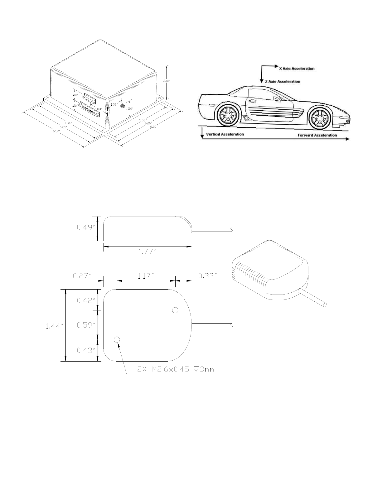
three (3) mutually perpendicular planes (see Figure 2). A unique feature is the two sets of
acceleration measurements. One set gives sensor acceleration with respect to the sensor mounting
face while the other set resolves the motion into horizontal and vertical components, irrespective of
the sensor attitude. This allows the earth's gravitational field to be isolated from the measurement
of sensor motion.
Product Description
Watson Industries DMS uses solid-state gyros and silicon accelerometers. Interface to the
microprocessor is done through a 16-bit A/D converter. The solid state vibrating structure angular
rate gyros used in this system provide extremely high reliability, low power consumption, shock
resistance and low cost. There are no physical adjustments required by the user. All of the primary
transducers are locked into position during manufacture. Adjustments are made with the aid of PC-
based maintenance software, which communicates with the DMS via the RS-232 serial connection.
Calibration is achieved by using the maintenance software to store data in non-volatile memory
within the DMS. The DMS-EGP01 differs from a “standard” DMS with the addition of a GPS
antenna and receiver. The GPS receiver also provides a vehicle velocity that is used to improve
accuracy in high dynamic environments. This is most useful with wheeled vehicles. This unit
outputs Latitude & Longitude based on the position of the antenna.
This unit will operate in two heading modes. In the first mode, the DMS uses the GPS module. In
this mode, the unit outputs track heading, does not take in commands and the vehicle speed is
digital. Please note that the Baud Rate needs to be set to 9600 when using the GPS module (any
selectable baud rate is acceptable when the GPS module is not in use). The heading needs to be in
the GPS Track mode and velocity input needs to be in the GPS Ground Track mode. (See
Appendix A Setting Velocity & Heading Modes)
In the second mode, the unit does not use the GPS module, it outputs relative heading, has the
ability to take in commands (double space bar mode) and the vehicle speed is an analog input. The
heading needs to be in the relative mode & velocity input needs to be in the Analog input mode.
(See Appendix A Setting Velocity & Heading Modes).
A vehicle speed input is used to assist in the correction of errors. It is also included in the
parameter set that is available for serial output. Although its use is not always required, it is highly
recommended that this signal be supplied to the DMS. The unit requires an analog/digital signal.
The analog signal is scaled to 40 KPH per volt. The digital signal is from the GPS module.
Forward motion should produce a positive signal with respect to signal ground. Many other
velocity scale factors can be handled through simple changes in the scale factor stored in the
EEPROM in the microprocessor. This can be done with a PC and the assistance of the factory.

Watson Industries, Inc. DMS-EGP01 Rev A 02/12/2015
4
Installation
Orientation
The connector face of the unit must point in the forward direction. The DMS drawing, with wire
call outs, is located in Figure 1. The DMS is a rugged device and will withstand harsh
environments. However, due attention needs to be paid to the nature of the sensor and its prime
function, which is to measure attitude and motion.
Mounting
The DMS-EGP01 has four 0.20” diameter mounting holes for 10-24 screws (See Figure 1). If high
shock loads are expected (greater than 20G or repeated shocks greater than 10G), appropriate shock
mounting should be used to prevent damage. Vibration isolation should be used if operation in 4G
or greater vibration environments is expected.
The GPS antenna has a magnetic mount with two M2.6 mounting holes and needs an unobstructed
view of the sky to receive signals from GPS satellites. The antenna needs to be mounted on a
minimum 6” x 6” ground plane. Nothing nearby the antenna can be higher than this ground plane.
Environment
Avoid mounting sites that are subject to significant temperature changes over the duration of the
test. Temperature variation will induce noticeable rate sensor bias drift, which will result in
degraded attitude accuracy.
Power / Connectors
This unit has an internal regulator to allow operation over a wide voltage input range. Best
operation is obtained at either 12 or 24 VDC, although operation is fully satisfactory down to 10
VDC and up to 30 VDC. Power draw of the unit is about 5.5 Watts. Internal capacitors are
provided to remove a reasonable level of power line noise, however, capacitors should be added for
long power line wiring or if noise is induced from other loads on the circuit. The DMS power
system is isolated from the DMS signal system. The mating connector for the Power/Analog
Output Connector is a 25 Pin female D-Sub.
Note: The signal ground is connected to case.
The SMA GPS antenna connector is on the side of the case. This type of connector should be
torqued to a maximum of 5 in-lbs. The GPS Antennas are supplied with +5 VDC, less than 40mA
each. The minimum gain requirement for these antennas is 20 dB. For more information on the
connectors and pinout of the DMS-EGP01, see Figure 1.
Calibration
The DMS is calibrated at the factory before it is shipped to the user. It is recommended that the
unit be returned to the factory annually for evaluation and recalibration.
Operation
Initialization
Ideally, the DMS should be stationary and level when it is turned on. If not, the sensor readings
may not be accurate for after initialization. The time required for the initialization process is not

Watson Industries, Inc. DMS-EGP01 Rev A 02/12/2015
5
the same for every type of DMS, but typically takes 4 to 5 seconds. During this time, a message is
sent from the unit via the RS-232 serial link. This message gives information about the DMS such
as the full model number, serial number, and software revision. The message can be read by using
a terminal program or by using the terminal mode of Watson Industries’ communication software.
The DMS can also be “re-initialized” after it has been turned on. This is especially useful if the
sensor has been used in severe maneuvers that have over-ranged the angular rate sensors and
caused significant errors to accumulate. Sometimes re-initializing the unit will allow for a faster
recovery than waiting for the error correction routines to correct the sensor readings. There are
several ways to re-initialize the DMS. For more information, see the Interface section of this
manual.
Normal Operation
During normal operation, the DMS will output highly accurate inertial data for the user to interpret.
This data is transmitted in several different ways. The most common way to acquire data from the
DMS is to use the RS-232 serial output. There are two RS-232 output formats: decimal and binary.
The exact formatting structure is discussed later in the Interface section of this manual. The DMS
generates twelve different data items for output: X, Y, and Z rates, X, Y, and Z accelerations, Bank,
Elevation, and Heading, and Forward, Lateral, and Vertical Accelerations. Any combination of
these data items can be selected for transmission via the RS-232 serial link. The DMS also has
analog outputs (see Interface section) that can be used to send data to the user.
In normal operation, the DMS takes data from its internal rate sensors and integrates in a closed
loop system, with the accelerometers as a long-term reference, to generate Bank, Elevation and
Heading data. In most cases, these algorithms provide for very stable and accurate output signals;
however, the user should be aware that exceeding the normal ranges of the sensors would affect
accuracy. For example, while custom DMS units may have differing ranges, the gyros in a typical
DMS have a maximum rate of 100°/s. Care should be taken not to exceed this rate because the
closed loop system will receive inaccurate data. This will result in errors in the angle output
signals.
While this DMS is "all attitude", the accuracy deteriorates rapidly when its forward direction is
within about 5 degrees of vertical. Operation for any extended period of time in this orientation is
not recommended. If these few operational precautions are observed, the DMS should provide
very accurate data for a wide variety of applications.
Special Operation Modes
Reference Mode
This mode is usually used for calibration or diagnostics. When in reference mode, the DMS will
output data generated directly from the sensor reference signals rather than as a product of the
closed loop integration used for normal operation. This mode provides sensor information similar
to normal operation mode with the following differences:
Bank and Elevation are obtained directly from the accelerometers - no gyro stabilization.
No heading information is available.
Angular Rate Sensors are not close-loop bias corrected.
The reference mode can be selected either through the terminal mode, or by an analog logic
command. Note that reference mode is never a default setting. It must be re-selected when re-
powering the unit.

Watson Industries, Inc. DMS-EGP01 Rev A 02/12/2015
6
Free Mode
While in Free Mode, the DMS will output data from the sensors without correction by the
references. For example, the Bank Angle data output in Free Mode is calculated directly from the
X axis Rate Sensor. In this case, the angle is a direct integration of the roll rate. Free Mode can be
used to totally reject effects from dynamic accelerations, but accuracy degrades with time. It is
intended for use over periods of a few minutes at a time. This mode provides sensor information
similar to normal operation mode with the following differences:
Bank and Elevation are obtained directly from the rate gyros.
No heading information is available.
Angular Rate Sensors are not close-loop bias corrected.
Free mode can be accessed either through terminal mode, or by an analog logic command. Note
that free mode is never a default setting. It must be re-selected when re-powering the unit. The
user should not enter free mode until after the DMS is initialized and its readings are stable.
Hold Mode
This mode inhibits bias adjustments to the gyros. It is intended for short-term use only since
leaving biases uncorrected will allow errors to accumulate over time. The accumulating bias error
will result in small attitude errors. Hold mode can provide better performance in highly dynamic
environments such as continuous circling over several minutes time. The user should not enter hold
mode until after the DMS is initialized and its readings are stable.
Control Mode
In this mode, the DMS will output sensor data normally unless it receives a control mode
command. Once a command is received, the DMS will send data in response and await the next
command. Using this mode, the user can retrieve the EEPROM map, baud rates, output formats,
and many other operational settings of this sensor. Having access to this information makes the
Control Mode useful in assisting the factory to remotely troubleshoot the certain operational
problems that can occur. For more details, see the RS-232 Input Commands section later in this
manual.
Interface
The DMS has analog, logic, and digital interface capabilities.
RS-232 Output Format
The standard RS-232 output consists of a string of decimal ASCII characters sent asynchronously
at regular intervals. Nominally, the string is sent at 9600 baud with eight data bits, one stop bit and
no parity. The mating connector for the RS-232 is a 9 Pin Male D-Sub. The number of strings sent
per second depends on the baud rate and the output format. The maximum rate is 71.11 strings per
second. See Appendix A for information on how to change the data string. The contents of a
typical string are formed as follows:
1. A single letter and a space used to indicate the start of the data string. The letter “G”
indicates the start of an inertial data string with successful GPS data input. The letter “I”
indicates the start of an inertial data string with GPS disabled or absence of valid GPS data.
The letter “R” indicates the start of a Reference data string. If the letter is in lower case
(“g”,“i”, or “r”), an error over-range condition is indicated (see below).
2. A seven character string representing the bank angle starting with a “+” or a “-“, followed
by three digits, a decimal point, one digit and a space for up to ±179.9 degrees.

Watson Industries, Inc. DMS-EGP01 Rev A 02/12/2015
7
3. A six character string representing the elevation angle starting with a “+” or a “-“, followed
by two digits, a decimal point, one digit and a space for up to ±89.9 degrees.
4. A six character string representing the heading angle by three digits, a decimal point, one
digit and a space for zero to 359.9 degrees.
5. A six character string representing the X axis angular rate starting with a “+” or a “-“,
followed by two digits, a decimal point, one digit and a space for up to ±99.9
degrees/second.
6. A six character string representing the Y axis angular rate starting with a “+” or a “-“,
followed by two digits,
a decimal point, one digit and a space for up to ±99.9
degrees/second.
7. A six character string representing the Z axis angular rate starting with a “+” or a “-“,
followed by two digits, a decimal point, one digit and a space for up to ±99.9
degrees/second.
8. A seven character string representing the Forward Velocity starting with a “+” or a “-“,
followed by three digits, a decimal point, one digit and a space for up to ±399.9 Km/Hr.
9. The string is terminated by a carriage return. There will then be a short interval with no
data transmission before the next string begins.
Example:
G
+002.5 -05.0 273.4 -00.4 +01.2 +10.4 +017.3 <CR>
↑↑↑↑↑↑↑
(1)
Bank
angle
(2)
elev.
angle
(3)
Head.
angle
(4)
X axis
rate
(5)
Y axis
rate
(6)
Z axis
rate
(7)
Forward
Velocity
(8)
(9)
space space space space space space space
The string transmission rate can be improved by reducing the amount of information (data items)
transmitted. The data items transmitted can be changed by using special commands to modify the
EEPROM of the unit (see Appendix A). In addition, more channels are available for output (see
Appendix A).
The system is protected from inadvertent write-over of the EEPROM by requiring two spacebar
commands during the initialization interval to access the EEPROM or related functions.
The baud rate may be changed from the nominal value of 9600 baud by modifying the default
value in the EEPROM of the unit to 38.4K, 19.2K, or 4800 baud. Please note that the Baud Rate
must be 9600 when using the GPS module.
A text header is sent by the DMS during initializations that identifies the unit by part number and
by serial number and gives the date of last calibration. Additionally, a line of text characters that
identifies the data channel columns is sent if the serial output is set to ASCII decimal. This whole
message can be temporarily or permanently suppressed or restored by a “*” command from the
interfacing computer.
Data transmission sent by the DMS can also be suppressed or restored by a “+” command from the
interfacing computer.

Watson Industries, Inc. DMS-EGP01 Rev A 02/12/2015
8
The error over-range condition is indicated by the use of a lower case “i” or “r” when the calculated
attitude or heading error exceeds the ranges listed above. Internal functions that require these error
values are disabled while the condition exists. The system will continue to operate in an extended
time constant mode with a low level of error accumulation until the condition is cleared. While
maneuvering the vehicle, occasional blips of this condition are expected with no detectable effect
on the resulting data.
The other output format available is a binary format. In this mode, the unit provides generally the
same information as the decimal ASCII format, but in a compact binary message. In this format,
there are nominally 13 words sent that represent 6 fourteen-bit output channels followed by a
carriage return. Again, the channels may be reduced to to improve the update rate by using special
commands to modify the EEPROM of the unit. This format is for highly experienced users only.
Consult the factory for further details.
RS-232 Input Commands
The RS-232 input commands are provided for the purpose of unit test and installation set-up. Use
the same parameters that are used for the RS-232 output (9600 baud ASCII nominal, or as reset in
the units EEPROM).
Note: Many commands require command or “Double spacebar mode” in order to access them. For
more information on how to activate Command Mode, see the instructions in the second part of
Appendix A.
These commands are available to the user (others are used at the factory for alignment and
calibration).
1. An “R” or “r” will set the outputs (analog and serial) to their Reference Command modes.
This will also disable the logic input Reference Command and Free Mode Command until
the next time the unit is powered up. This mode is used in installation to physically align
the unit. Double spacebar at initialization is required for access to this command.
2. An “I” or “i” sets the unit to Inertial mode. This is the default mode at power up and is the
normal operating mode. Switching to this mode clears the Reference Command mode if it
had been set by the serial input. This will also disable the logic input Reference Command
and Free Mode Command until the next time the unit is powered up. Double spacebar at
initialization is required for access to this command.
3. An “F” or “f” will disconnect the references from the attitude system and is the Free Mode
Command. Free mode is used to make the system ignore the references during high
maneuvers and brief disturbances. This mode is not intended for use except in brief
intervals, since errors will grow geometrically. This will also disable the logic input
Reference Command and Free Mode Command until the next time the unit is powered up.
Double spacebar at initialization is required for access to this command.
4. An “H” or “h” will remove bias correction from the system and is the Hold Mode
Command. This mode is useful is highly dynamic situations that may last for a few minutes.
Hold mode should not be used for more than a few minutes, because errors can accumulate.
Double spacebar at initialization is required for access to this command.
5. A “K” or “k” will clear the Free Mode Command and Hold Mode Command.

Watson Industries, Inc. DMS-EGP01 Rev A 02/12/2015
9
6. An “!” will reinitialize the unit. Further, the access to initialization is inhibited such that a
spacebar command must be sent within 2.5 seconds of the “!” command for initialization to
be engaged. This command does not require a double space bar at initialization to be in
effect.
There are two output format commands: “_” for decimal output and “^” for binary. See the second
part of Appendix A for more information on changing output formats. There are several interface
commands as well: “:” will toggle the output to send a frame of data upon receiving any non-
command character and “+” will toggle the output for no output data. These and other changes
can be made permanent by keying in the quote (“) character. Double spacebar at initialization is
required for access to all of these commands.
The “&” command calls a menu which allows any of several parameters to be set. From this menu,
the user can change system time constants, data channels for serial output, heading source, velocity
source and baud rate. Double spacebar at initialization is required for access to this command.
The commands “~”, “@”, “#”, “$”, ‘(“, “)”, “{“, “}”, “|”, “<”, “>” and “?” are used by the Watson
factory to calibrate the unit and should be used only with the assistance of the factory. If an
undesired function is called, a “Q”, and sometimes Escape or a Delete will interrupt the command
and return to operation with the least disturbance to the system. All other unspecified characters
such as carriage return, line feed and space are ignored by the system.
If there are problems with the system “hanging up” during the binary output mode, check for cross-
talk between the serial transmit and receive line in your installation. In addition, check to see that
the communications program used is not sending an echo. This will not happen in the decimal or
hexadecimal modes because command characters recognized by the system are not produced in
those modes.
Analog Outputs
Analog signals are output from a 14 bit digital to analog converter through an operational amplifier.
Each analog output has a 300 ohm resistor in series to eliminate oscillations from high capacitance
loads. The output range for all of the analog output channels is ±10 Volts with respect to the
common signal ground. The outputs include:
Signal Pin Range Output Range 0 VDC Scale Factor
Bank 14 ±180°±10V 0° 18°/s/V
Elevation 15 ±90°±5V 0° 18°/s/V
Heading 16 0-360°±10V 0° (North) 18°/s/V
Roll Rate (X Axis) 23 ±100°/s ±10V 0°/s 10°/s/V
Pitch Rate (Y Axis) 24 ±100°/s ±10V 0°/s 10°/s/V
Yaw Rate (Z Axis) 25 ±100°/s ±10V 0°/s 10°/s/V
X Acceleration 17 ±10g ±10V 0g 1g/V
Y Acceleration 18 ±10g ±10V 0g 1g/V
Z Acceleration 19 ±10g ±10V 0g 1g/V
Forward Acceleration 20 ±10g ±10V 0g 1g/V
Lateral Acceleration 21 ±10g ±10V 0g 1g/V
Vertical Acceleration 22 ±10g ±10V 0g 1g/V
Note that the analog switches are disabled after certain serial commands are sent to the unit. This
prevents software/hardware switch conflicts.

Watson Industries, Inc. DMS-EGP01 Rev A 02/12/2015
10
Analog Inputs
In an effort to make this system more versatile, the DMS allows the user to input analog data that
can then be added to the serial data output. This allows the system to act as a data acquisition unit
for other vehicle information such as engine RPM, engine temperature, fuel remaining,
altitude/depth or any other important data. The four analog user inputs as well as the velocity input
have one megohm input impedance, 16 bit A/D conversion resolution, ±10 volt input range and
have a bandwidth of DC to 25 Hertz.
Speed Inputs
A vehicle speed input is used to assist in the correction of errors. It is also included in the
parameter set that is available for serial output. Although its use is not always required, it is highly
recommended that this signal be supplied to the DMS. The unit can receive speed information in
two formats, an analog or digital signal.
The analog speed input signal is a voltage that is scaled to 40 KPH per volt. Forward motion
should produce a positive signal with respect to signal ground. Many other velocity scale factors
can be handled through simple changes in the scale factor stored in the EEPROM in the
microprocessor. This can be done with a PC and the assistance of the factory.
The digital signal that the DMS can receive is from the GPS module.
Output Logic Commands
Initialization lasts 4 seconds, during which time the "Ready" signal is set low (0v). Once
Initialization is complete, the "Ready" signal is set high (+5VDC). The ready signal is on pin 9 of
the 25 pin connector.
Input Logic Commands
The DMS also has several digital inputs that are all activated by connecting to signal ground. The
user should only apply a ground because all the inputs have a pull-up resistor to +5VDC. The pins
are as follows:
a) Initialization - Resets all angle integrators. The unit should be in a non-accelerated
condition if this command is given. Leave pin open if not in use. Ground to command.
b) Reference - An alternate set of sensor information primarily intended as an
instrumentation mode. Leave pin open if not in use. Ground to command.
c) Coast (Free Inertial) – In this mode, the attitude is computed from gyro data only. Free
mode is used when extreme accelerations are expected. Leave pin open if not in use.
Ground to command.
NOTE: The analog digital inputs are all disabled if any equivalent serial command is sent via RS-
232. This is to prevent hardware/software conflicts.

Watson Industries, Inc. DMS-EGP01 Rev A 02/12/2015
11
Specifications
Attitude
Range: Bank ±180°
Range: Elevation ±75°
Resolution: 0.02° Binary mode (14 bit)
Analog Scale Factor: 18°/V ±10V Output
Accuracy: Static ±0.25°
* Accuracy: Dynamic ±0.5%
GPS Heading
Range: 0° - 360°
Resolution: 0.02° Binary mode (14 bit)
Analog Scale Factor: 18°/V ±10V Output
Accuracy: Static ±0.5° (±0.05°/sec stationary) Relative, based on gyro drift
* Accuracy: Dynamic ±0.5%
Angular Rate
Range: Roll, Pitch, Yaw ±100°/sec
Resolution: 0.025°/sec Binary mode (14 bit)
Analog Scale Factor: 10°/sec/V ±10V Output
Scale Factor Accuracy: ±0.5%
Bias: Roll, Pitch, Yaw < 0.2°/sec (Analog) ±0.02°/sec Binary mode (14 bit)
Non-Linearity: < 0.1% Full scale range
Bandwidth: 20 Hz
Noise: < 0.03°/sec rms
Acceleration
Range: X, Y, Z ±10g
Range: Forward, Lateral, Vertical ±10g
Resolution: 4mg
Analog Scale Factor: 1g/V ±10V Output
Scale Factor Accuracy: 1%
Bias: X, Y, Z < 10mg
Non-Linearity: 0.1% Full scale range
Bandwidth: 3 Hz
GPS Positioning
Range: Latitude ±90°
Range: Longitude ±180°
Range: Altitude 0ft to 21500ft
Resolution: Latitude, Longitude 0.0000013° Binary mode (28 bit)
Resolution: Altitude 2 ft
Accuracy: Latitude, Longitude 1.5m rms
Environmental
Temperature: Operating -40°C to +85°C
Temperature: Storage -55°C to +85°C
Vibration: Operating 5g rms 20 Hz to 2 KHz
Vibration: Survival 10g rms 20 Hz to 2 KHz
Shock: Survival 500g 10mS ½ sine wave
Electrical
Frame Rate: 71.1 Hz Maximum
Startup Time: Data 5 sec
†
Startup Time: Satellite Acquisition 5 min Typical
Input Power: 10 to 30VDC 5.5W
Input Current: 458mA @ 12VDC 229mA @ 24VDC
Input Velocity: (Optional) ±10VDC Full scale (±400kph)
Digital Output: RS-232
Analog Output ±10VDC
Physical
Axis Alignment: < 0.1°
Size: Including Mounting Flanges 6.5"W x 6.5"L x 3.1"H 16.5 x 16.5 x 7.9 (cm)
Weight: 52oz (3.2lb) 1470 grams (1.5Kg)
Connection: RS-232 9 pin female "D" subminiature
Connection: Power / Analog Outputs 25 pin male "D" subminiature
Connection: Antenna SMA Antenna cable length: 3.0m
* Using velocity data with GPS mode on.
Actual accuracy can be calculated as the listed percentage multiplied by the change in value over the entire dynamic maneuver.
† Acquisition time for GPS units is typical for the contiguous United States. Acquisition time may differ due to interference in your geographic area.
• Specifications are subject to change without notice.
• This product may be subject to export restrictions. Please consult the factory.

Watson Industries, Inc. DMS-EGP01 Rev A 02/12/2015
12
FORWARD
Y
HANDLE WITH CARE
DELICATE INSTRUMENT
CAUTION
Z
Y
Y
Z
X
X
Z
WATSON INDUSTRIES, INC.
www.watson-gyro.com
MADE IN U.S.A
P/N
REV
PWR
S/F
S/N:
Connections / Dimensions
Figure 1 DMS-EGP01
25 Pin Male D-Sub
Power/Analog Output Connector
Pin Description
1 Power Ground *
2 +12 or +24 VDC
3 - 6 User Inputs 1 - 4
7 Not Used
8 Coast Command
9 Ready
10 Initialization Command
11 Velocity Input (option)
12 Signal Ground
13 Reference Command
14 Bank Angle Analog Output
15 Elevation Angle Analog Output
16 Heading Angle Analog Output
17 X Axis Acceleration Analog Output
18 Y Axis Acceleration Analog Output
19 Z Axis Acceleration Analog Output
20 Forward Acceleration Analog Output
21 Lateral Acceleration Analog Output
22 Vertical Acceleration Analog Output
23 Roll Rate Analog Output
24 Pitch Rate Analog Output
25 Yaw Rate Analog Output
* Power Ground and Signal Ground are
electrically isolated.
9 Pin Female D-Sub RS-232 Serial
Communication Connector
Pin Description
1 No Connection
2 TXD**
3 RXD
4 Shorted to pin 6
5 Ground
6 Shorted to pin 4
7 Shorted to pin 8
8 Shorted to pin 7
9 No Connection
** The user receives on this line.
Watson Industries, Inc. DMS-EGP01 Rev A 02/12/2015
13
Figure 2 Antenna Dimensions

Watson Industries, Inc. DMS-EGP01 Rev A 02/12/2015
14
Warning
Rough handling, dropping, or miswiring this unit is likely to cause
damage.
DISCLAIMER
The information contained in this manual is believed to be accurate and reliable; however, it is the
user’s responsibility to test and to determine whether a Watson Industries’ product is suitable for a
particular use.
Suggestion of uses should not be taken as inducements to infringe upon any patents.
WARRANTY
Watson Industries, Inc. warrants, to the original purchaser, this product to be free from defective
material or workmanship for a period of two full years from the date of purchase. Watson
Industries’ liability under this warranty is limited to repairing or replacing, at Watson Industries’
sole discretion, the defective product when returned to the factory, shipping charges prepaid, within
two full years from the date of purchase. The warranty described in this paragraph shall be in lieu
of any other warranty, express or implied, including but not limited to any implied warranty of
merchantability or fitness for a particular purpose.
Excluded from any warranty given by Watson Industries are products that have been subject to
abuse, misuse, damage or accident; that have been connected, installed or adjusted contrary to the
instructions furnished by seller; or that have been repaired by persons not authorized by Watson
Industries.
Watson Industries reserves the right to discontinue models, to change specifications, price or
design of this product at any time without notice and without incurring any obligation whatsoever.
The purchaser agrees to assume all liabilities for any damages and/or bodily injury that may result
from the use, or misuse, of this product by the purchaser, his employees or agents. The purchaser
further agrees that seller shall not be liable in any way for consequential damages resulting from
the use of this product.
No agent or representative of Watson Industries is authorized to assume, and Watson Industries
will not be bound by any other obligation or representation made in connection with the sale and/or
purchase of this product.
PRODUCT LIFE
The maximum expected life of this product is 20 years from the date of purchase. Watson
Industries, Inc. recommends the replacement of any product that has exceeded the product life
expectation.

Watson Industries, Inc. DMS-EGP01 Rev A 02/12/2015
15
Customer Service
All repairs, calibrations and upgrades are performed at the factory. Before returning any product,
please contact Watson Industries to obtain a Returned Material Authorization number (RMA).
Return Address & Contact Information
Watson Industries, Inc.
3035 Melby Street
Eau Claire, WI 54703
ATTN: Service Department
Telephone: (715) 839-0628 Fax: (715) 839-8248 email: support@watson-gyro.com
Returning the Product
Product shall be packaged making sure there is adequate packing around all sides. Correspondence shall
include:
• Customer’s Name and Address
• Contact Information
• Equipment Model Number
• Equipment Serial Number
• Description of Fault
It is the customer’s responsibility to pay all shipping charges from customer to Watson
Industries, including import and transportation charges.

Watson Industries, Inc. DMS-EGP01 Rev A 02/12/2015
16
Appendix A
The following outputs are available via the RS-232 serial link. Their full-scale ranges are listed for both decimal and
binary format.
Inertial Output Full Scale Decimal Full Scale Binary
Time Since Reset UTC
1
HHMMSS Seconds since Reset
16,383 seconds
Bank Angle ±179.9º ±180º
Elevation Angle ±89.9º ±180º
Heading Angle 0.0 to 359.9º ±180º
X Accelerometer ±9.99 G ±10 G
Y Accelerometer ±9.99 G ±10 G
Z Accelerometer ±9.99 G ±10 G
Forward Acceleration ±9.99 G ±10 G
Lateral Acceleration ±9.99 G ±10 G
Vertical Acceleration ±9.99 G ±10 G
X Angular Rate ±99.9 º/s ±200 º/s
Y Angular Rate ±99.9 º/s ±200 º/s
Z Angular Rate ±99.9 º/s ±200 º/s
Heading Rate ±99.9 º/s ±200 º/s
Corrected Bank Pendulum (simulated)
±179.9º ±180º
Corrected Elevation Pendulum (simulated)
±89.9º ±180º
User Channel 1 ±9.99 VDC ±10 VDC
User Channel 2 ±9.99 VDC ±10 VDC
User Channel 3 ±9.99 VDC ±10 VDC
User Channel 4 ±9.99 VDC ±10 VDC
Ground Track
2
/ Forward Velocity ±399.9 Km/hr ±400 Km/hr
Latitude
3
±89.99999 ±90º (4 bytes)
Longitude
3
±179.99999 ±180º (4 bytes)
Altitude
4
21500 Feet 21500 Feet (2 Feet/count)
Temperature -40º to 88ºC -40º to 88ºC (7 bit)
Status Bits 3 ASCII chars representing
Octal digits 1 byte
Flag Bits 3 ASCII chars representing
Octal digits 1 byte
1
Note: The GPS universal time (UTC) field is filled with asterisks when the data is invalid.
(“******”)
2
Note: The Ground Track Velocity field is filled with asterisks when the data is invalid.
(****.*)
3
Note: The Latitude & Longitude fields are filled with asterisks when the data is invalid. (“+**.***** +***.*****”)
4
Note: The Altitude field is filled with asterisks when the data is invalid.
(*****)
The Status Bits contain the following information:
Bit Description (If Set)
0 Bank Error Flag
1 Elevation Error Flag
2 Heading Error Flag
3 System Error Flag
4 Velocity Error Flag
5 Ready Flag
6 Checksum Error Flag
7 Not Used (always zero)
Example: The status channel output in ASCII Decimal is “146”
Octal Digit 1 4 6
Binary Equivalent 0 1 1 0 0 1 1 0
Status Bit # 7 6 5 4 3 2 1 0

Watson Industries, Inc. DMS-EGP01 Rev A 02/12/2015
17
Bit 7 Reset
Bit 6 Set Checksum Error
Bit 5 Set Ready
Bit 4 Reset No Velocity Error
Bit 3 Reset No System Error
Bit 2 Set Heading Error
Bit 1 Set Elevation Error
Bit 0 Reset No Bank Error
The Flag Bits contains the following information:
Bit Description
0 GPS Heading fail.
1 GPS Velocity fail.
2 Not used (always zero)
3 Reference Command selected
4 GPS enabled
5 Free Mode selected
6 Analog Switches disabled
7 Not used (always zero)
Example: The flag channel output in ASCII Decimal is “120”
Octal Digit 1 2 0
Binary Equivalent 0 1 0 1 0 0 0 0
Status Bit # 7 6 5 4 3 2 1 0
Bit 7 Reset
Bit 6 Set Analog Switches Disabled
Bit 5 Reset Not in Free Mode
Bit 4 Set GPS Enabled
Bit 3 Reset Not in Reference Mode
Bit 2 Reset
Bit 1 Reset Valid GPS velocity data
Bit 0 Reset Valid GPS heading data

Watson Industries, Inc. DMS-EGP01 Rev A 02/12/2015
18
Activating Command mode or Double Spacebar Access to commands
Hook the unit up to your computers serial port.
Use HyperTerminal program to interface with unit.
Turn on unit. Wait for the startup message to appear on display.
Hit the space bar twice within the first 5 seconds of turn on.
Sometimes it takes a few tries to get the hang of this.
Wait for the data string to start transmitting.
Now the unit will take in the keyboard commands.
Determining and Setting Output Channels
Activate Command Mode (See above)
To determine which channel present, first type '&'.
This will bring up the menu:
Typing in '3' will show which channels are currently active.
To change which channels are output type '&'(this will bring up the menu again)
Now type '2' to set up channels
The following message will appear:
To proceed type 'Y' or “y”
Now each channel will come up one at a time
For example:
Type 'Y' or “y” to output channel, type 'N' or “n” to remove channel
When you get to bottom of list, this message will appear:
TYPE IN THE NUMBER OF YOUR SELECTION (OR 'Q' TO QUIT):
1 = ADJUST TIME CONSTANTS
2 = SET OUTPUT CHANNELS
3 = LIST CURRENT OUTPUT CHANNEL SELECTION
4 = SELECT HEADING SOURCE
5 = SELECT VELOCITY SOURCE
6 = SELECT ALTITUDE CORRECTION
7 = SET NEW BAUD RATE
TO SET FOR OUTPUT FOR ANY OF THE FOLLOWING DATA ITEMS, PRESS Y
TO AVOID ANY OF THE FOLLOWING DATA ITEMS, PRESS N
TO QUIT AND DISREGARD ANY OTHER DATA, PRESS Q
*** DO YOU WANT TO PROCEED? (Y/N/Q)
DO YOU WANT OUTPUT OF TIME?
Y = GOBACK, N = INSTALL DATA & QUIT, Q = QUIT
DO YOU WANT TO TRY TO SET DATA AGAIN?

Watson Industries, Inc. DMS-EGP01 Rev A 02/12/2015
19
To accept channels type 'N' or “n”, then hit space bar output data to resume.
To make this channel selection the default the next time you power the unit on type in " (a quote mark)
Setting Output Format
There are two output formats:
Decimal output – “_” Command.
Binary output – “^” Command.
To change the output format:
Activate Command Mode (See above).
Press the key Command corresponding to the format you want to switch into.
To make this channel selection the default the next time you power the unit on type in " (a quote mark.)
Setting Heading Mode
Activate Command Mode (See above).
To set the heading mode, type in &.
This will bring up the menu:
Typing in ‘4' will bring up this menu:
To set the heading mode to Track Heading type ‘1’. To use this mode, the GPS antenna must be connected to the
DMS.
To set the heading mode to Relative Heading type ‘2’. This is the normal DMS mode (non-GPS). In this mode, the
GPS antennas do not need to be connected.
To make any of these modes the default the next time you power the unit on type in " (a quote mark.)
Setting Velocity Mode:
Activate Command Mode (See above).
To set the velocity mode, type &.
This will bring up the menu:
TYPE IN THE NUMBER OF YOUR SELECTION (OR 'Q' TO QUIT):
1 = ADJUST TIME CONSTANTS
2 = SET OUTPUT CHANNELS
3 = LIST CURRENT OUTPUT CHANNEL SELECTION
4 = SELECT HEADING SOURCE
5 = SELECT VELOCITY SOURCE
6 = SELECT ALTITUDE CORRECTION
7 = SET NEW BAUD RATE
TYPE IN THE NUMBER OF YOUR SELECTION (OR 'Q' TO QUIT):
1 = ADJUST TIME CONSTANTS
2 = SET OUTPUT CHANNELS
3 = LIST CURRENT OUTPUT CHANNEL SELECTION
4 = SELECT HEADING SOURCE
5 = SELECT VELOCITY SOURCE
6 = SELECT ALTITUDE CORRECTION
7 = SET NEW BAUD RATE
SELECTION HEADING SOURCE (OR 'Q' TO QUIT):
1 = GPS TRUE NORTH GROUND TRACK HEADING
2 = RELATIVE HEADING

Watson Industries, Inc. DMS-EGP01 Rev A 02/12/2015
20
Typing in ‘5' will bring up this menu:
To set to GPS Ground Velocity type ‘1’. This is the mode when using the GPS module.
To set to Analog Velocity type ‘2’. This is the normal DMS mode (non-GPS). Make sure that the proper analog
velocity signal is applied.
To make this selection the default the next time you power the unit on type in " (a quote mark.)
SELECTION VELOCITY SOURCE (OR 'Q' TO QUIT):
1 = GPS GROUND TRACK VELOCITY
2 = ANALOG VELOCITY
This manual suits for next models
1
Table of contents
Other WATSON INDUSTRIES GPS manuals


Popular GPS manuals by other brands


Fjallcom
Fjallcom Satellite SOS InReach SE+ user guide

Rand McNally
Rand McNally TND 765 user manual

Navigon
Navigon Sync 8100T user guide

satmap
satmap active 20 Full user guide

Garmin
Garmin GPS 152 - Marine Receiver Owner's manual and reference guide

Geneq
Geneq iSXBlue II GNSS Series Technical reference manual