Digital Matter G62 User manual

G62
Installation Guide
Revision 1.0 -20 September 2018
All information provided in this document is subject to legal disclaimers © Digital Matter 2018
G62 Installation Guide Revision 1.0 - 20 September 2018 Page 1 of 15
Need help? Go Online to our Knowledge Base support.digitalmatter.com
Contents
1. Introduction .................................................................................................. 2
2. In the Box..................................................................................................... 2
3. Wiring Harness............................................................................................. 3
Wiring Harness Diagram.........................................................................3
Wiring Harness Description ....................................................................4
4. Getting Started............................................................................................. 4
Insert the SIM.........................................................................................4
Insert the battery.....................................................................................5
Check the device has connected............................................................5
4.3.1. LED Behaviour..................................................................................5
4.3.2. OEM Installer Page...........................................................................5
4.3.3. Check connection with the OEM Installer Page.................................6
Housing Assembly..................................................................................9
5. Install Location............................................................................................. 9
6. Installation.................................................................................................. 10
Connect Power and Ignition..................................................................10
6.1.1. Testing............................................................................................10
Driver ID –Connecting an iButton Reader............................................10
Connecting Digital Inputs......................................................................11
6.3.1. Testing............................................................................................11
Wiring for Immobilisation.......................................................................11
6.4.1. Wiring for Immobilisation on no Driver ID........................................12
6.4.2. Wiring for Remote Immobilisation....................................................12
Appendix A –Wiring Diagram –Immobilisation on no Driver ID........................ 13
Appendix B –Installer Page Details.................................................................. 14
Appendix C –Firmware and Parameter Updates.............................................. 15
Digital Matter G62 Install Guide
All information provided in this document is subject to legal disclaimers © Digital Matter 2018
G62 Installation Guide Revision 1.0 - 20 September 2018 Page 2 of 15
1. INTRODUCTION
The G62 is a compact 4G GPS tracking device with a variety of inputs and outputs to cater for
the most demanding applications. The 4G modem allows for operation on both Cat-M1 and NB-
IoT networks. Its rugged housing is IP67 rated to withstand the harshest environments, without
sacrificing tracking and communications performance. With the internal GPS and cellular
antennas installation is a breeze. The internal backup battery provides alerts and tracking
operations even when external power is removed.
This guide will help you install and test a G62.
Need help? Go Online to our Knowledge Base support.digitalmatter.com
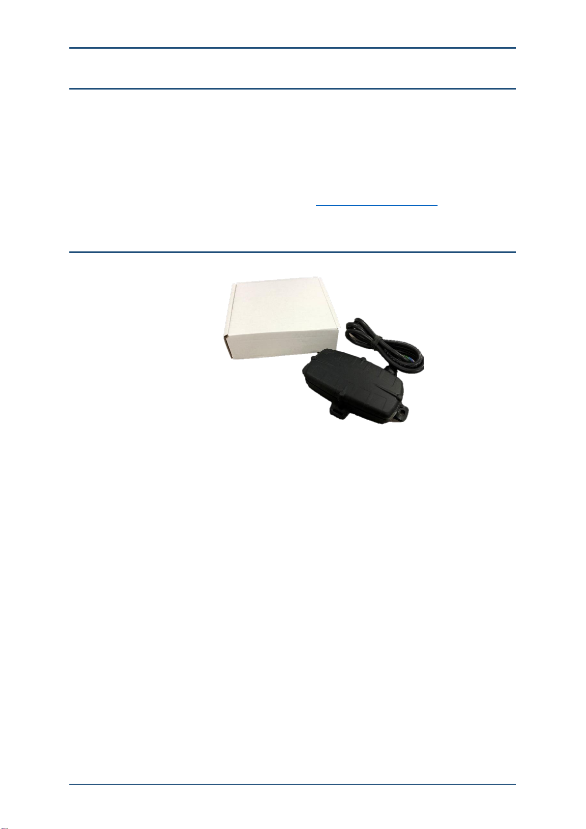
2. IN THE BOX
You'll get a compact box containing the G62 and a small packet containing the 4 housing screws.
The GPS and GSM antennas are internal –none are required to be installed.

G62
Installation Guide
Revision 1.0 -20 September 2018
All information provided in this document is subject to legal disclaimers © Digital Matter 2018
G62 Installation Guide Revision 1.0 - 20 September 2018 Page 3 of 15
3. WIRING HARNESS
Wiring Harness Diagram
G62
Installation Guide
Revision 1.0 -20 September 2018
All information provided in this document is subject to legal disclaimers © Digital Matter 2018
G62 Installation Guide Revision 1.0 - 20 September 2018 Page 4 of 15
Wiring Harness Description
Colour
Function
Notes
Red
External Power
8 –36V DC external power
Black
Ground
Main Ground
White
Ignition
0 –50V DC, permanent internal pull down
Blue
Digital Input 1
0 –50V DC, configurable pull down
Yellow
Digital Input 2
0 –50V DC, configurable pull down
Brown
iButton
iButton input
Green
Analogue Input/Switched
Ground Output
Low side switch. Use with a relay, LED, or buzzer.
0 –30V Analogue Input
4. GETTING STARTED
The G62 may be damaged by electrostatic discharge if not handled correctly. Ensure
adequate static precautions are taken. Consider wearing an anti-static wrist guard. Avoid
touching the antennae and any of the electronic components on the PCB. Take special care not
to touch the ceramic GPS antenna as static can damage the sensitive GPS circuitry.
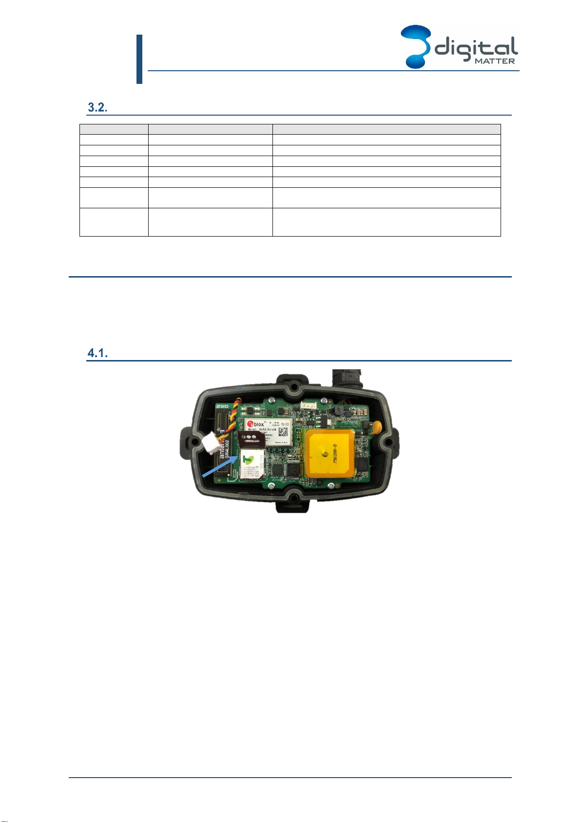
Insert the SIM
1. The SIM holder is located on the top side of the main PCB.
2. Unplug the battery and remove any external power connections.
3. Slide the locking mechanism on the SIM holder to the “unlock” position, and lift the
hinged portion of the SIM holder.
4. Insert the micro SIM into the holder with the keyed corner orientated away from the
hinge and the SIM contacts orientated down to the PCB (see example above).
5. Close the SIM holder and slide the locking mechanism to the “lock” positon.
To easily get up and running:
1. The SIM should not have a PIN on it, unless you use the device specific PIN.
2. The SIM should have credit or airtime
3. The SIM should use one of the APN's built into the firmware. It is possible to set APN's
by SMS

Digital Matter G62 Install Guide
All information provided in this document is subject to legal disclaimers © Digital Matter 2018
G62 Installation Guide Revision 1.0 - 20 September 2018 Page 5 of 15
Insert the battery
The battery should be provided disconnected inside the housing. The battery plug is a three-
way connector on the top side of the PCB.
1. Insert the battery plug into the connector. It should only be possible in one orientation.
2. The LED on the board will light up and flash if the battery has sufficient charge.
Batteries are supplied fully charged.
3. Route the battery wires into the space between the GPS board and the housing. Take
care to avoid trapping the wires when sealing the device.
Check the device has connected
4.3.1. LED Behaviour
The battery should come pre-charged. Once you insert it, the internal LED will come on and
flash.
The LED will flash slowly at first. When it opens a connection to the server, it will flash fast.
Once data is sent, it will go solid briefly, and revert to flashing fast. When the device goes to
sleep, the LED will switch off.
If the battery is too low, use the harness to provide external power.
If the LED flashes but the G62 does not connect, check the SIM is in the holder correctly and
check that the SIM is working. Further troubleshooting steps are discussed further on in this
document.
4.3.2. OEM Installer Page
The OEM Installer page is designed to verify than an installation has been done correctly. We
will be using it going forward in this document.
It is not password protected, and as such is designed to not give any sensitive information
away.
To access the page, go to www.oemserver.com/installer

Digital Matter G62 Install Guide
All information provided in this document is subject to legal disclaimers © Digital Matter 2018
G62 Installation Guide Revision 1.0 - 20 September 2018 Page 6 of 15
4.3.3. Check connection with the OEM Installer Page
Further testing of inputs/ignition etc will be required once the device is wired in, but for now we
will simply test the device can connect and acquire a GPS fix before going any further.
1. Type in the device serial (6-digit number found underneath the device)
2. Click on Find

Digital Matter G62 Install Guide
All information provided in this document is subject to legal disclaimers © Digital Matter 2018
G62 Installation Guide Revision 1.0 - 20 September 2018 Page 7 of 15
The following details will be displayed. See Appendix B –Installer Page Details for a full
description of each field.

Digital Matter G62 Install Guide
All information provided in this document is subject to legal disclaimers © Digital Matter 2018
G62 Installation Guide Revision 1.0 - 20 September 2018 Page 8 of 15
Work through these steps in order, to check the device is connecting in and getting a GPS
fix. If an earlier step fails, the data in later steps may not be accurate. For example, if the
device is not connecting, the Battery Voltage will be based on older data, and will not be
current.
1. Check Last Connection (1) to check that the device connected recently. This means the
device is connecting to OEM. The time shown should be around about the time you inserted
the SIM and battery to power on the unit.
2. If device is connecting (1) check Last Commit (2) to see if it is sending data. If the connector
is set, it must be setup on the software platform that is meant to receive the data. e.g.
Telematics Guru.
3. Check the time of the last GPS update (3). It should be recent.
4. Check the battery level (4) is acceptable for the device type. It should be between 3.5-4.2V
(around 3.5V is flat)
Troubleshooting
If the device does not connect (1) check the following:
•If the sim card has been inserted correctly.
•If the sim card has enough mobile data on it and is active (contact your reseller if required)
•If external voltage is connected properly.
•If the device is running, based on LED flashes (see 4.3.1)
•The device is using the correct APN –contact your reseller if you are unsure
If the device does not commit (2) check the following:
•If the device is setup on the platform that the connector points to. e.g. Telematics Guru.
Check that both the serial number and device type are correct on the platform. (Contact your
reseller for assistance)
If the device does not update GPS (3) check the following:
•The device has a clear view of the sky
If there are crosses showing for (5), (6), (7) or (8), consult Appendix C –Firmware and
Parameter Updates for more information.
You can now continue with the installation.

Digital Matter G62 Install Guide
All information provided in this document is subject to legal disclaimers © Digital Matter 2018
G62 Installation Guide Revision 1.0 - 20 September 2018 Page 9 of 15
Housing Assembly
Ensure that the main PCB is secured to the housing with the 4 small PCB screws and that the
SIM is inserted as above. Ensure that the device is online before sealing it.
1. The seal should be the latest Digital Matter clear silicon seal to ensure the IP rating of the
housing.
2. Ensure that the seal is in the base and lying flat, and that there is not dust or dirt on the seal.
3. Ensure the battery cable will not be pinched by the lid and place it onto the base.
4. Insert the 4 x 20mm housing screws. Note that G52S screws look similar but are 25mm in
length. DO NOT use G52S screws as they will crack the plastic housing when tightened.
5. Hand tighten the screws to a uniform tightness.
6. Ensure that the cable gland is tightened around the cable.
Please make sure that you take extra precautions to ensure that the device has been sealed
adequately when it will be installed in environments where it is exposed to the weather or water
or liquid spraying. The Digital Matter manufacturer’s warranty does not cover damage due to
water ingress as the final installation is not performed by Digital Matter.
5. INSTALL LOCATION
The housing has mounting holes for screws, bolts or cable ties.
There are a few considerations for the final mounting position of the G62.
The G62 has been engineered to have the best possible GPS reception. It will work from inside
engine bays, body panels, under dashboards and other places where other GPS devices
simply fail to operate reliably.
Although the G62 will work in these locations it is always advisable to install the G62 where it is
best able to get signals from the GPS satellites, with the optimum position being a location with
a clear 180-degree view of the sky.

Digital Matter G62 Install Guide
All information provided in this document is subject to legal disclaimers © Digital Matter 2018
G62 Installation Guide Revision 1.0 - 20 September 2018 Page 10 of 15
6. INSTALLATION
Connect Power and Ignition
Connect the following wires to the vehicle:
1. Red (external power) to the vehicle positive - 8 to 36V (MAX). Verify this supply is
constant, even when the vehicle is switched off. Sometimes other (non-constant)
signal lines can appear to be a 12 or 24V constant supply.
2. Black (Ground) to the chassis ground
3. White (Ignition) to an ignition source –something that will be on when the vehicle ignition is
on, and off when the ignition is off.
6.1.1. Testing
Use the installer page to verify the External Power (1) and Ignition (2) is operating correctly.
The Ignition input should change from off to on when you toggle the vehicle’s ignition.
Driver ID –Connecting an iButton Reader
The G62 can read Driver ID tags using the following reader.:
- iButton reader: Dallas iButton tags.
Connections for the Digital Matter harness are as follows –Other iButton readers will work but
may have different harness colours.
iButton Harness wire colours:
Colour
Function
Red
iButton Signal Line
Black
Ground
Green
Green LED
Brown
Red LED
Yellow
LED Negative
The brown and green wires on DM harnesses have 1000-ohm resistors connected in series.
For a simple implementation (read driver ID, LEDs won't light up) connect the following wires:
Digital Matter G62 Install Guide
All information provided in this document is subject to legal disclaimers © Digital Matter 2018
G62 Installation Guide Revision 1.0 - 20 September 2018 Page 11 of 15
G62 Wire Colour
iButton Wire Colour
Brown (iButton input)
Red (iButton signal line)
G62 or vehicle GND
Black (GND)
Connecting Digital Inputs
When installing digital inputs, make note of how they are installed, and how the ‘switch’
operates. It is useful to know so that your reseller can apply the correct settings to the device.
Digital Matter Devices have two important settings for digital inputs. Bias Resistor and Active
Level.
Bias Resistor: The bias resistor essentially determines the state of the input when nothing is
connected to the input. Options are pull-up (hold input high), pull-down (hold low), and disable.
The default is usually pull up
Active Level: Determines the physical line level which is logged as ‘on’ by the device.
Common examples of digital inputs are:
•Duress buttons –push button connected between a digital input wire and ground. Pushing the
button closes the circuit to ground, which we want to register as ‘Active’
In this scenario we would set Bias Resistor = Pull up, and Active Level = Low
•PTOs –Input wire on device is connected to high side of PTO, so when the machine is on
and there is a voltage on this line we want the input to be ‘ON’ and 0V as ‘OFF’.
In this scenario we would set Bias Resistor = Pull down, and Active Level = High
6.3.1. Testing
The installer page can again be used to verify that digital inputs are correctly wired.
Note:
By default, the device will not connect and report upon input changes –it simply logs them and
uploads later (this can be changed) so you might not see them change quickly.
However, when the ignition is on, the device will connect and stay connected to the server –so
input changes will show immediately. Hence it is worthwhile testing your inputs with the ignition
on if possible and safe to do so.
Toggle the inputs with the ignition on, and confirm they are correctly setup via the installer
page.
If the settings described above have not yet been applied or are incorrect the physical on/off
state of the input might not match what is shown in the Installer Page.
Wiring for Immobilisation
The G62 has a switched ground output. This type of output, when ‘ON’ provides a ground, and
when ‘OFF’ is high impedance.
The switched ground output is used to control the negative side of a relay coil, which will open
or close a circuit to provide a starter motor cut. The specific pins used vary dependant on use
case, with the aim to ensure the energy is not energised when the vehicle is not running,
causing a drain on the battery.
Devices support 2 kinds of immobilisation:
1. Driver ID - Vehicle is immobilised until the correct driver ID is entered, then
immobilisation is turned off

Digital Matter G62 Install Guide
All information provided in this document is subject to legal disclaimers © Digital Matter 2018
G62 Installation Guide Revision 1.0 - 20 September 2018 Page 12 of 15
2. Remote Immobilisation - Device can be sent a command to immobilise the vehicle.
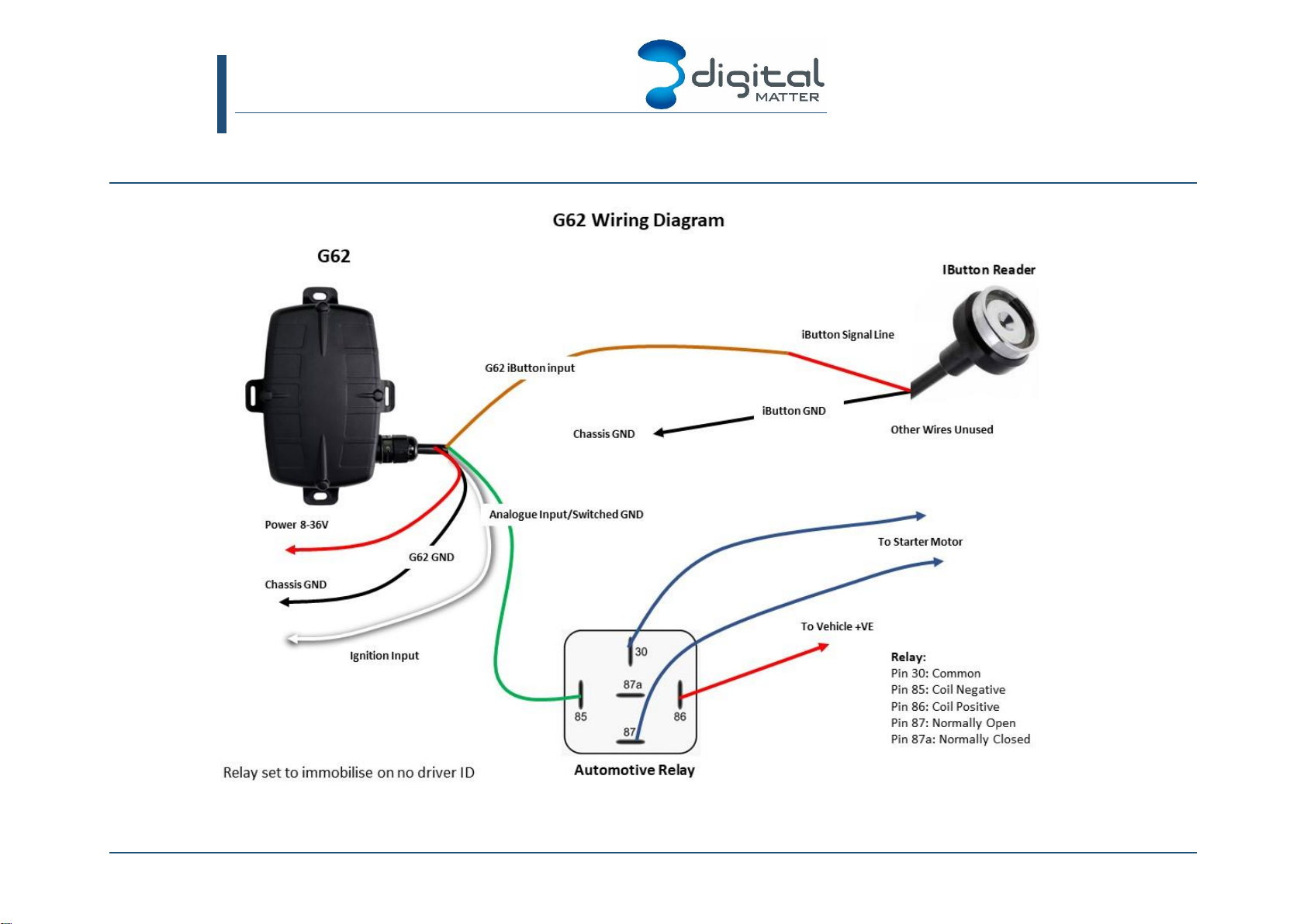
6.4.1. Wiring for Immobilisation on no Driver ID
See our Knowledge Base article on this: G62 Immobilisation Setup for Access Control
1. Connect the relay coil positive (PIN 86), to the vehicle positive
2. Connect the relay coil negative (PIN 85), to the switched ground output (GREEN on G62)
3. Use the common (PIN 30) and Normally Open (PIN 87) contacts to control the starter
motor.
In this configuration the relay is not energised until the driver ID is scanned, at which point it will
be energised allowing the vehicle to be started.
See Appendix A –Wiring Diagram –Immobilisation on no Driver ID for a wiring diagram
for this configuration.
6.4.2. Wiring for Remote Immobilisation
1. Connect the relay coil positive (PIN 86), to the vehicle positive
2. Connect the relay coil negative (PIN 85), to the switched ground output (GREEN on G62)
3. Use the common (PIN 30) and Normally Closed (PIN 87a) contacts to control the starter
motor.
In this configuration the relay is energised when the command is sent from the server to
immobilise, and the starter motor is cut.
G62
Installation Guide
Revision 1.0 -20 September 2018
All information provided in this document is subject to legal disclaimers © Digital Matter 2018
G62 Installation Guide Revision 1.0 - 20 September 2018 Page 13 of 15
APPENDIX A –WIRING DIAGRAM –IMMOBILISATION ON NO DRIVER ID
G62
Installation Guide
Revision 1.0 -20 September 2018
All information provided in this document is subject to legal disclaimers © Digital Matter 2018
G62 Installation Guide Revision 1.0 - 20 September 2018 Page 14 of 15
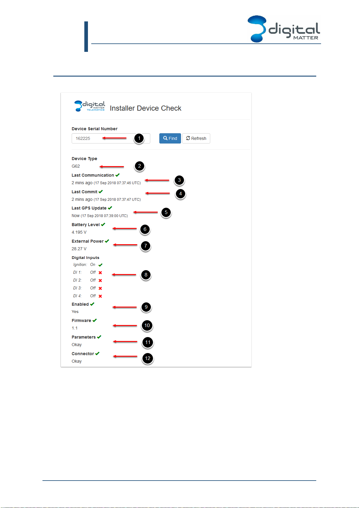
APPENDIX B –INSTALLER PAGE DETAILS
The installer page displays the following information:
1. Device Serial Number
2. Device Type
3. Last Communication –gives the time the device last connected into OEM. Connected
simply means a hello message was sent.
4. Last Commit –gives the time the device last uploaded data records. If the device has
a connector set, this implies that data was successfully sent to the connected
software platform.
5. Last GPS Update –Gives the time the device got its latest GPS position
6. Battery Level –Internal Battery Level. Will be marked with a cross if it is too low for
your device type (flat or disconnected battery)

Digital Matter G62 Install Guide
All information provided in this document is subject to legal disclaimers © Digital Matter 2018
G62 Installation Guide Revision 1.0 - 20 September 2018 Page 15 of 15
7. External Power –Voltage read at the external power input of the device.
8. Digital Inputs –Status of ignition and other digital inputs
9. Enabled –Whether the device is enabled in OEM. If it is not enabled contact your
reseller
10. Firmware –Current Firmware version. This will be marked with a cross if there is a
pending firmware update. For example:
This image indicates that the device is currently on firmware version 1.9, but it has
been set in OEM server to update to 1.18 on the next connection
11. Parameters –As for firmware, this will be marked with a cross and “Pending” if new
parameters have been set in OEM but the device has not yet downloaded and set
them.
12. Connector –A connector forwards data on from the OEM server to an end tracking
platform. If it is not set, but the device is still committing (4), the OEM Installer page
will operate fine for testing purposes.
APPENDIX C –FIRMWARE AND PARAMETER UPDATES
If a firmware or parameter update is pending, the update will be downloaded on the next
connection. Updates will not be applied while the device is in trip.
To speed up applying updates, power cycle the external power on the device, this triggers an
upload. Alternatively cycle the ignition, though remember leaving the ignition on means the
device will stay connected to the server and not apply its updates.
Other manuals for G62
1
Table of contents
Other Digital Matter GPS manuals

Digital Matter
Digital Matter Dart User manual

Digital Matter
Digital Matter Sting User manual

Digital Matter
Digital Matter Bolt User manual

Digital Matter
Digital Matter Oyster Sigfox User manual

Digital Matter
Digital Matter Oyster2 User manual

Digital Matter
Digital Matter G100 Iridium Hybrid User manual

Digital Matter
Digital Matter G62 User manual


