Watson-Marlow MC100 User manual

User’s Manual
MC100
MC100 DeviceNet OM 1.01 EN.doc Version: 1.01 Page 1 of 36
MC100
Pump Control Module
User’s Manual
(DeviceNet)

Users Manual
MC100
MC100 DeviceNet OM 1.01 EN.doc Version: 1.01 Page 2 of 36
CONTENTS:
1Introduction................................................................................................................................ 4
1.1 Abbreviations in this manual ..................................................................................................... 4
1.2 Precautions ............................................................................................................................... 4
1.3 References ................................................................................................................................ 4
2General description of MC100...................................................................................................5
2.1 Overview ................................................................................................................................... 5
2.2 Introduction & design purpose...................................................................................................5
2.2.1 How it works / Technical description of operation ..................................................................... 5
3Technical specifications ............................................................................................................ 6
3.1 Dimensions................................................................................................................................ 6
3.2 Specifications ............................................................................................................................ 7
3.3 Unpacking and inspection of MC100......................................................................................... 8
3.3.1 Identifying the module ...............................................................................................................8
3.3.2 Identifying the parts ...................................................................................................................9
3.4 Mounting.................................................................................................................................... 9
3.4.1 Choosing a place to mount the MC100 ..................................................................................... 9
4Wiring ...................................................................................................................................... 10
5Fieldbus network node address and front plate indicators ...................................................... 12
5.1 Network node address switches S1/S2:..................................................................................12
5.2 P1/P2 LED indicators: ............................................................................................................. 12
5.3 Display P4/P5.......................................................................................................................... 13
5.3.1 Start up states: ........................................................................................................................ 13
5.3.2 Network address ..................................................................................................................... 13
5.3.3 Alarm- and warning display ..................................................................................................... 13
5.3.4 Dipswitch ................................................................................................................................. 13
6Configuring the fieldbus network to the MC100 ......................................................................14
6.1 Connecting the MC100 and the pumps for the first time ......................................................... 14
6.2 Configuring the DeviceNet network.........................................................................................15
7Operating the MC100 .............................................................................................................. 16
7.1 Process Data Exchange (Cyclic data)..................................................................................... 16
7.1.1 Process control bits for MC100 ............................................................................................... 16
7.1.2 Process status bits from MC100 .............................................................................................17
7.1.3 Process control bits for the pumps .......................................................................................... 18
7.1.4 Process status bits from the pumps ........................................................................................ 19
7.2 Operation Parameters / Parameter specifications................................................................... 20
7.2.1 List of basic ADI’s.................................................................................................................... 20
7.2.2 List of additional ADI’s............................................................................................................. 21
7.2.3 Detailed description of the ADI’s ............................................................................................. 22
8Alarm and warnings................................................................................................................. 29
8.1 Alarms handling....................................................................................................................... 29
8.1.1 Alarms ..................................................................................................................................... 29
8.2 Warnings handling................................................................................................................... 30
8.2.1 Warnings ................................................................................................................................. 30
9Trouble shooting...................................................................................................................... 31
9.1 Trouble-shooting list ................................................................................................................ 31
9.2 Opening the MC100 for service/replacement of PCB’s........................................................... 32
10 Decommissioning .................................................................................................................... 33
10.1 Advice about dismantling / removal / disposal ........................................................................33
10.2 Environmental conditions / -regulations ..................................................................................33
10.3 The WEEE system .................................................................................................................. 33
11 Appendix 1 .............................................................................................................................. 34

Users Manual
MC100
MC100 DeviceNet OM 1.01 EN.doc Version: 1.01 Page 3 of 36
12 Declaration of Conformity........................................................................................................ 36

Users Manual
MC100
MC100 DeviceNet OM 1.01 EN.doc Version: 1.01 Page 4 of 36
1 Introduction
1.1 Abbreviations in this manual
Fieldbus DeviceNet, Profibus, CANOpen etc.
Fieldbus interface module Anybus Compact Com Module from HMS
Filling system System consisting of an MC100 and from 1 to 16 pumps
Pumps All Watson-Marlow Flexicon pumps types that communicates on Flexnet
WMF Watson-Marlow Flexicon
1.2 Precautions
This manual should be read thoroughly before using the MC100.
It is strongly advised that
- No wiring is connect or disconnect on the MC100, while power supply is turned ON
- The MC100 must mounted in an environment, that adheres to EN 60204-1:2006 4.4.3-6
- The MC100 must not to be used in explosion hazardous environments.
1.3 References
- EN 60204-1:2006

Users Manual
MC100
MC100 DeviceNet OM 1.01 EN.doc Version: 1.01 Page 5 of 36
2 General description of MC100
2.1 Overview
MC100 is a Pump control module capable of controlling up to 16 WMF Pumps. The basic function is
to receive filling data from the filling line control system through an industrial fieldbus and to calculate
operating values for the pumps. Transmit/ Receive those values and status through the FlexNet
protocol.
MC100 constitutes with WMF Pumps a filling system that is designed for incorporation into a larger
facility as described below.
Pump
Pump
Pump
Pump
Product
MC100
Filling line control system
incl. storing of recipe and
HMI
Scale
Recipe
Commands
Actual
parameter
Status
Achieved
fill amount
Filling system
2.2 Introduction & design purpose
The MC100 is physically a small module intended for mounting inside the control cabinet of the filling
line.
The MC100 is designed with the purpose of integrating Watson-Marlow Flexicon pumps into a filling
line. The MC100 has no physical operator interface, all access to the module and hence the pumps is
done through the fieldbus interface module
2.2.1 How it works / Technical description of operation
Recipes, containing parameters, such as filling volume and filling speed for the requested filling, are
sent to the MC100 via the fieldbus communication. The MC100 will, based on these specifications
calculate operating parameters for all the pumps and transfer these parameters to the pumps
Parameters will be sent to and status retrieved from the pumps by the RS485 multidrop network using
the proprietary FlexNet communication protocol.
All control signals and status signals from the pumps are available through the fieldbus interface, but
start and status signals can be sent to / received directly from the individual pump by 24V signals.

Users Manual
MC100
MC100 DeviceNet OM 1.01 EN.doc Version: 1.01 Page 6 of 36
MC100 holds no recipes, historical data or audit trail, only current runtime parameters for the filling
system is stored internally.
3 Technical specifications
3.1 Dimensions

Users Manual
MC100
MC100 DeviceNet OM 1.01 EN.doc Version: 1.01 Page 7 of 36
3.2 Specifications
Fieldbus:
- DeviceNet
Pumps:
Max 16 pumps can be connected and controlled.
Pumps must be able communicate with MC100 via FlexNet protocol.
Material and surface treatment:
- Mounting box made from aluminium.
- All aluminium parts anodised (conductive).
Environmental:
- Ingress protection according to IP30.
- NEMA 1 enclosure.
- EN 60204-1:2006.
Mounting:
- MC100 is to be mounted on DIN rail size 35.
Power supply:
- Supply 24 VDC ± 10%.
- Power consumption less than 10 VA.
- Fuse max. 1A
Weight:
- 0.5 kg.

Users Manual
MC100
MC100 DeviceNet OM 1.01 EN.doc Version: 1.01 Page 8 of 36
3.3 Unpacking and inspection of MC100
With the shipment of MC100 you should receive:
•The MC100
•Declaration of Conformity
•CD-rom with documentation:
Manual for installation, programming and service of MC100
Documentation and support-files for Anybus CompactCom fieldbus module
Please check that all ordered items have been received and that no items were damaged during
transport. In case of any defects or omissions, please contact WMF or your supplier immediately.
Please verify that the model number stated on the nameplate and the installed fieldbus connector
matches your purchase order.
Model number on nameplate Fielbus connector
MC100 61-120-000 DeviceNet
3.3.1 Identifying the module
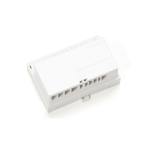
MC100 module:
Rotary switches
Fieldbus connector
2-digit LED display
8-bit switch
9-pin SUB D connect
Power supply
Flexnet connector
LED - Busy
LED - Online

Users Manual
MC100
MC100 DeviceNet OM 1.01 EN.doc Version: 1.01 Page 9 of 36
3.3.2 Identifying the parts
- MC100 module.
- Connector for Flexnet.
- Connector for Power Supply.
- Connector for Fieldbus.
3.4 Mounting
3.4.1 Choosing a place to mount the MC100
The MC100 must be mounted in an environment that adheres to the specifications in 3.2.
Be sure that the MC100 is also protected from the following conditions
- Rain and moistures
- Corrosive gasses
- Dust or metallic particles in the air
- Physical shock or vibration
- Magnetic noise (Examples welding machines, power devices, etc.)
On the left side of the module is located a dipswitch (se 3.1), which should be accessible.

Users Manual
MC100
MC100 DeviceNet OM 1.01 EN.doc Version: 1.01 Page 10 of 36
4 Wiring
MC100 Frontplate
10
3
4
9
6
8
5
7
2
10
3
4
9
6
8
5
7
2
X1
X2
X3
X4
Connectors
COMM
BUSY
1
1
X1 Flexnet Connector Connect with
1 /DATA I/O
2 GND -
3 DATA I/O
PHOENIX
MC 0,5/ 3 –G-2,5THT
PHOENIX
FK MC 0,5/ 3 –ST 2,5
The Flexnet connector should be connected to the corresponding terminals on all the pumps,
establishing a multidrop network and the last pump should be terminated with a 120 ohm
resistor between DATA and /DATA.
Use 0.25 – 0.35 mm2 wires twisted or screened. Terminal tubes must be minimum 8 mm long.
X2 Power Supply Connector Connect with
1 N.C. -
2 +24V IN
3 0V IN
4 0V IN
PHOENIX
MC 0,5/ 4 –G-2,5THT
PHOENIX
FK MC 0,5/ 3 –ST 2,5
Use 0.5 mm2 wires, terminal tubes must be minimum 8 mm long.

Users Manual
MC100
MC100 DeviceNet OM 1.01 EN.doc Version: 1.01 Page 11 of 36
X3 Communication Connector Connect with
1 RS485 – A I/O
2 TxD OUT
3 RxD IN
4 N.C.
5 GND -
6 NC
7 CTS OUT
8 RTS IN
9 RS485 – B I/O
9 pole SubD Male 9 pole SubD female
X4 Fieldbus Interface DeviceNet Connect with for example
1 OV Black V-
2 Data Blue CAN_L
3 Shield - SHIELD
4 Data White CAN_H
5 +24V Red V+
PHOENIX Part number
28 62 57 6

Users Manual
MC100
MC100 DeviceNet OM 1.01 EN.doc Version: 1.01 Page 12 of 36
5 Fieldbus network node address and front plate indicators
MC100 Frontplate
10
3
4
9
6
8
5
7
2
10
3
4
9
6
8
5
7
2
Indicators / Switches
COMM
BUSY
P1
P2 P4 / P3
S2 / S1
5.1 Network node address switches S1/S2:
The node address is setup on the 2 rotary switches S1 and S2.
Address-range 1 to 99
The address is normally set before powering up and connecting to the network for the first time, but if
the address is change after power up, the new address will flash on P4/P5 display for 5 seconds,
where it is possible to change back to the old address.
After 5 seconds the MC100 will do a total factory reset and start up using the new address.
5.2 P1/P2 LED indicators:
Green Continuously ON or flashing indication communication with the pumps
P1 Red Flashing indicates Lost connection to at least 1 pump or internal error
Green Currently not used
ON indicates at least 1 pump is active
P2 Red Flashing together with P1 indicate fatal internal error in the module.

Users Manual
MC100
MC100 DeviceNet OM 1.01 EN.doc Version: 1.01 Page 13 of 36
5.3 Display P4/P5
This display is used for general indication of the start up states in the MC100 and for various other
purposes.
5.3.1 Start up states:
P4/P5 Description Note
S U Initial start up state
S.U. Internal communications started
S.0. Start initialisation of the fieldbus module Short state if no errors
S.1. Cyclic data now exchangeable with the network Short state if no errors
S.2. MC100 ready and waiting for connection
S.3. Intermediate state / special network state Short state
S.4. Connection to network established and working Short state
S.5. Internal error during initialization Steady state (see trouble shooting)
S.7. Internal error during initialization Steady state (see trouble shooting)
S 8 Factory Reset to default – initiating from Dipswitch
S 9 Factory Reset to default
5.3.2 Network address
After initialization, the display is showing the network node address.
5.3.3 Alarm- and warning display
The node address is replaced by a flashing:
AL and the alarm number XX,when and alarm is present (see 8.1.1 Alarms).
Er and the warning number XX, when a warning (recoverable alarm) is present (see 8.1.2 warnings).
5.3.4 Dipswitch
The dipswitch on the right side of the MC100 module can used to do a factory-reset function.
Reset state Dipswitch Action Description
0 All OFF None Normal runtime state
1 All OFF Remove power to MC100
2 SW 8 ON Apply power to MC100
MC100 starts up and reaches init state 2
And the restart again initializing to factory
defaults and starts up.
3 SW 8 ON Remove power to MC100
4 SW 8 OFF Apply power to MC100 MC100 starts up normally
The factory reset can be necessary to do before trying to connect to fieldbus network.
During the factory reset initialization, the MC100 determines how many and what pump types are
connected on the Flexnet. Based on this, the MC100 determines the number of cyclic data bytes to be
exchanged on the fieldbus, which MUST be set to same number in the fieldbus network configuration
(see 6.x.x).

Users Manual
MC100
MC100 DeviceNet OM 1.01 EN.doc Version: 1.01 Page 14 of 36
6 Configuring the fieldbus network to the MC100
6.1 Connecting the MC100 and the pumps for the first time
Make sure all pumps have been giving a unique address and all the pumps have been powered up.
The Flexnet is connected with MC100 and to the pumps in a multidrop network.
Connect SubD connector X3 to a PC using a NULL-modem cable.
Start a terminal program on the PC for example HyperTerminal.
Set the communication-parameters to: 9600 baud, 8 bits, even parity and 1 stop-bit.
When applying power to the MC100, it will identify itself by printing the line:
“ MC100 MFSC Ver. x.yy.” (x.yy will be the current version)
The MC100 will then try to identify all connected pumps on the Flexnet; the LED indicator X1 will
flicker and finally be steady green.
If for example 4 pumps are detected, the following line will be:
“Pumps: 1 2 3 4 1 4 4”
Stating that pumps numbered 1-4 are detected, lowest number is 1 and highest number is 4 totalling 4
pumps.
If the 2nd line is not printed and the MC12 has an Alarm indication: AL01 or AL02 flashing, it must be
investigated if the Flexnet is correct wired.
If all is OK, then continue to configure the DeviceNet scanner with RSNetWorx (see below).

Users Manual
MC100
MC100 DeviceNet OM 1.01 EN.doc Version: 1.01 Page 15 of 36
6.2 Configuring the DeviceNet network
The description is on how to configure the MC100 for DeviceNet using RSNetWorx is described in the
HMS document DeviceNet RSNetWorx 1 03.pdf, the newest verison can be downloaded from
http://www.hms.se/support/support.asp?PID=324&ProductType=Anybus-CompactCom.
In section 4.4 Configuring the I/O size and Mapping in the document please use the examples
below in stead for configuration:
Example 1: This will configure for MC100 with 1-2 pumps (Minimum configuration)
Example 2: This will configure for MC100 with 3-4 pumps
Always add 2 bytes when increasing from for example 4 to 5 pumps to keep the structure of always
increasing the cyclic bytes with min 2 bytes (see 7.1 Process Data Exchange (Cyclic data) below)

Users Manual
MC100
MC100 DeviceNet OM 1.01 EN.doc Version: 1.01 Page 16 of 36
7 Operating the MC100
7.1 Process Data Exchange (Cyclic data)
The cyclic data consists of control bits and status bits.
There is a distinction between MC100 control/status bits and pumps control/status bits.
When connected to the Fieldbus network the MC100 will always transmit and receive 1 word for the
MC100 function and minimum 1 word for the pumps (even if only 1 pump is connected there will still
be allocated 1 word, where the highest 8 bits will be empty).
7.1.1 Process control bits for MC100
There is allocated one word (2 bytes) for MC100 control bits as shown below.
Word 0
15 14 13 12 11 10 9 8 7 6 5 4 3 2 1 0
B1.7 B1.6 B1.5 B1.4 B1.3 B1.2 B1.1 B1.0 B0.7 B0.6 B0.5 B0.4 B0.3 B0.2 B0.1 B0.0
B0.0-4: Sets the active pump number
B0.4-7 Reserved for future use
B1.0: Mode bit 0
B1.1: Mode bit 1
MC100 working modes: 1Mode bit 0 Mode bit 1
Individuel “1” “0”
Parallel “0” “1”
Seriel “1” “1”
B1.2-4 Reserved for future use
B1.5 Alarm reset: will reset lowest number alarm or warning
B1.6 Rescan for pumps: resulting in new values for connected pumps (See ADI 12)
B1.7 Total reset of MC100 including loading the default values to connected pumps.
1See Appendix 1 for description of the working modes

Users Manual
MC100
MC100 DeviceNet OM 1.01 EN.doc Version: 1.01 Page 17 of 36
7.1.2 Process status bits from MC100
Status bits cyclic process data
For MC100 status one word (2 bytes) is dedicated as scheduled below.
Word 0
15 14 13 12 11 10 9 8 7 6 5 4 3 2 1 0
B1.7 B1.6 B1.5 B1.4 B1.3 B1.2 B1.1 B1.0 B0.7 B0.6 B0.5 B0.4 B0.3 B0.2 B0.1 B0.0
B0.0-4 Active pump number
B0.4-7 Reserved for future use
B1.0 Mode status bit 0
B1.1 Mode status bit 1
MC100 mode status: Mode status bit 0 Mode status bit 1
Individuel “1” “0”
Parallel “0” “1”
Seriel “1” “1”
B1.2-3 Reserved for future use
B1.4 Ready to receive acyclic ADI parameters (explicit messages)
B1.5 Parameter error – is reset when new parameter is accepted.
B1.6 Ready
B1.7 Alarm
Note B1.4 in the MC100 control bits is used as a READY- /BUSY bit for explicit parameter
transfers, the bit will go low when accepting an explicit parameter transfer and will go high
again when the data is processed, thereby enabling a new transfer, this handshake
mechanism MUST be respected otherwise data will be lost.

Users Manual
MC100
MC100 DeviceNet OM 1.01 EN.doc Version: 1.01 Page 18 of 36
7.1.3 Process control bits for the pumps
To control each pump one byte (8 bits) is dedicated as described below.
Minimum one word is transmitted for pump control. The number of pumps connected is a parameter,
which is part of the configuration of the number of cyclic bytes of the network.
Word 8 Word 7 Word 6 Word 5 Word 4 Word 3 Word 2 Word 1
P16 P15 P14 P13 P12 P11 P10 P9 P8 P7 P6 P5 P4 P3 P2 P1
Bit mapping in each command byte:
7 6 5 4 3 2 1 0
Direction
Disable in
Par./Serial RESET PUMP DISP START
Bit 0: START Starts a single Dispense cycle, when the Pump is set in Dispense mode (Bit. 1)
This bit must be cleared upon receiving the BUSY bit in the status byte for the
pump, see below.
Bit 1: DISP Sets the pump in dispense mode and thereby enables the START bit to start
dispenses. If removed during a dispense, the pump stops immediately.
Bit 2: PUMP2Starts pump running continuously with the speed set in ADI 3.
Bit 3: Reserved for future use
Bit 4: RESET To be used with future pumps
Bit 5: Disable pump in parallel and serial mode.
Bit 6: Direction3[1/0] [Backwards/Normal] pump and dispense direction.
Bit 7 Reserved for future use
2The DISP bit has higher priority and must be cleared before setting the PUMP bit.
3Available for pumps able to handle this function (GD30).

Users Manual
MC100
MC100 DeviceNet OM 1.01 EN.doc Version: 1.01 Page 19 of 36
7.1.4 Process status bits from the pumps
To retrieve status from each pump, one byte (8 bits) is dedicated as described below.
Minimum one word is received with status from the pumps. The number of pumps connected is a
parameter, which is part of the configuration of the number of cyclic bytes of the network.
The MC100 will always automatically send the number of bytes for the connected pumps, after a
factory reset to defaults.
Word 8 Word 7 Word 6 Word 5 Word 4 Word 3 Word 2 Word 1
P16 P15 P14 P13 P12 P11 P10 P9 P8 P7 P6 P5 P4 P3 P2 P1
Bit mapping in the status byte:
7 6 5 4 3 2 1 0
ALARM Direction DONE Pump Dispense Tube Br. BUSY READY
Bit 0: READY Pump is ready (self check is OK).
Bit 1: BUSY “1” Indicate that the pump is active, either dispensing or pumping
“0” pump is idle
Bit 2: Tube Br. Tube bridge bit: ”1” = tube bridge on, “0” = tube bridge off.
Bit 3: Dispense Dispense bit: “1” = dispense mode
Bit 4: Pump Pump bit: “1” = pump mode
Bit 5: DONE 4Set, when pump goes from dispensing to idle / reset by a new START bit.
Bit 6: Direction Handshake for bit B5 from command byte (0=normal / 1=reverse direction.)
Bit 7: ALARM See Chapter 8 for further information
4The DONE bit can be necessary to use if there is very short filling times, where the BUSY signal is not detected because of
transmission times on the fieldbus network.

Users Manual
MC100
MC100 DeviceNet OM 1.01 EN.doc Version: 1.01 Page 20 of 36
7.2 Operation Parameters / Parameter specifications
The parameters for the MC100 can be accessed using explicit messages on the DeviceNet Network.
The following specification based on the HMS Anybus CompactCom software specification for
DeviceNet
The parameters are in the Application Data Object.
The object can be accessed using Class A2 (162 decimal) object.
The basic parameters in then MC100 are in so called Data Application Instances (ADI’s) and each
ADI has attributes described in the tables below, where the data types are described.
7.2.1 List of basic ADI’s
The list shows the basic ADI’s which must be accessed, when controlling the pumps via the MC100.
ADI No. Description Data type Range Default
1 Volume Double integer 1000-999990000 10000000
2 Tube Integer 1-10 6
3 Speed Integer 30-600 100
4 Acceleration Integer 1-200 10
5 Reverse Integer 0-5 0
6 Density Double integer 50000 - 200000 100000
7 Calibration value Double integer 50 –200 % of Volume - - -
The data types for ADI1, 6 and 7 are special in that this data format has been chosen in stead of
floating point, to be able to use the MC100 with PLC’s without floating point capability.
The data type is a double word type where there is a hidden fixed decimal point position with 5
decimals.
Examples: Floating point value 123.45678 must be send to the MC100 as 12345678 or
Floating point value 1.2 must be send to the MC100 as 120000
In the PLC or HMI there must be a conversion to this format (i.e. multiply with 100000), if the input is
in floating point format. Likewise, if reading for example volume from the MC100, then divide the value
with 100000 to display it as a floating point.
The tube in ADI 2 is a number from 1-10, as the maximum number of tubes in a pump is 10, the
actual tubes sizes available for the pump, can be retrieved via ADI 13 or ADI 16.
The format is 10*inner tube diameter. Example: 48 equal tube size 4.8 mm
It’s possible for to read minimum and maximum values from the ADI’s to be used as limitations for
inputs, but the MC100 will also handle these ranges and discard the input and set a warning if out of
range, the warning will automatically be cleared if a value within the range is sent, but can also be
cleared using B1.5 Alarm reset bit in MC100 control bits.
IMPORTANT: When reading or writing to ADI’s a pump, it MUST FIRST be selected using the
cyclic bits B0.0-4 in the MC100 control bits, because the parameters will ALWAYS be for this pump.
Table of contents
