Sleipner SEP250 User manual

SLEIPNER AS
P.O. Box 519
N-1612 Fredrikstad
Norway
www.sleipnergroup.com
DOCUMENT ID:
REVISION:
DATE:
LANGUAGE:
Installation Guide
For Pro DC Electric Thruster Models
SEP250, SEP300
EN
I M
524 6
12
2 0 21

2524 6 12 2 0 21
-
SEP 250 & SEP 300
Sleipner Motor AS
P.O. Box 519, Arne Svendsensgt. 6-8
N-1612 Fredrikstad, Norway
MC_0020
Contents
Products
SEP300/300TC - SEP300 tunnel thruster 48v
SEP250/300TC - SEP250 Tunnel thruster, 24v
Installation Manual
Responsibility of the Installer..............................................................................................................................................................3 - 4
Thruster Measurements ....................................................................................................................................................................... 5
Thruster Specications........................................................................................................................................................................... 6
Technical Specications ....................................................................................................................................................................... 6
Proportional Technicial Specications ..................................................................................................................................................... 6
Positioning of the tunnel / thruster.......................................................................................................................................................... 7
Tunnel Length......................................................................................................................................................................................... 8
Tunnel installation in sail boats............................................................................................................................................................... 9
Water Deection ................................................................................................................................................................................... 10
Tunnel ends .......................................................................................................................................................................................... 11
Tunnel installation.......................................................................................................................................................................... 12 - 13
Stern tunnel installation ........................................................................................................................................................................ 14
Gear Leg & Motor Bracket Installation.................................................................................................................................................. 15
Propeller Installation............................................................................................................................................................................. 16
Motor Installation .................................................................................................................................................................................. 17
Thruster Electrical Installation .............................................................................................................................................................. 18
Electrical Specications ....................................................................................................................................................................... 19
Technical Wiring Diagram ............................................................................................................................................................. 20 - 21
S-Link System Description .................................................................................................................................................................... 22
Control Panel Cable Installation .......................................................................................................................................................... 23
Control Panel Installation ..................................................................................................................................................................... 24
Pre-delivery Checklist .......................................................................................................................................................................... 25
Service and Support........................................................................................................................................................................... 26
Product Spare Parts and Additional Resources.............................................................................................................................. 26
Warranty Statement............................................................................................................................................................................ 26

3
524 6 12 2 0 21
-
SEP 250 & SEP 300
MC_0031
General Installation Considerations and Precautions for Electric Thrusters
• The thruster must NOT be installed in compartments that require ignition proof electric equipment. If necessary, make a separate compartment.
(NB: Ignition Protected systems are tested to be installed in areas with possible explosive gases in accordance with ISO 8846)
• When installing the thruster electro motor in small compartments, ensure the compartment is well ventilated to allow for cooling of the electro
motor.
• If the height of the room you are installing the thruster is limited, the thruster can be installed horizontally or at any angle in-between.
- If the electro motor is positioned more than 30 degrees off vertical, it must be supported separately.
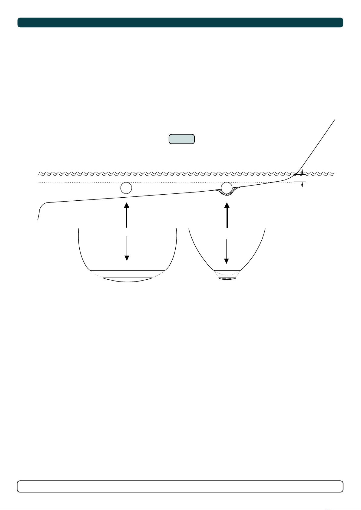
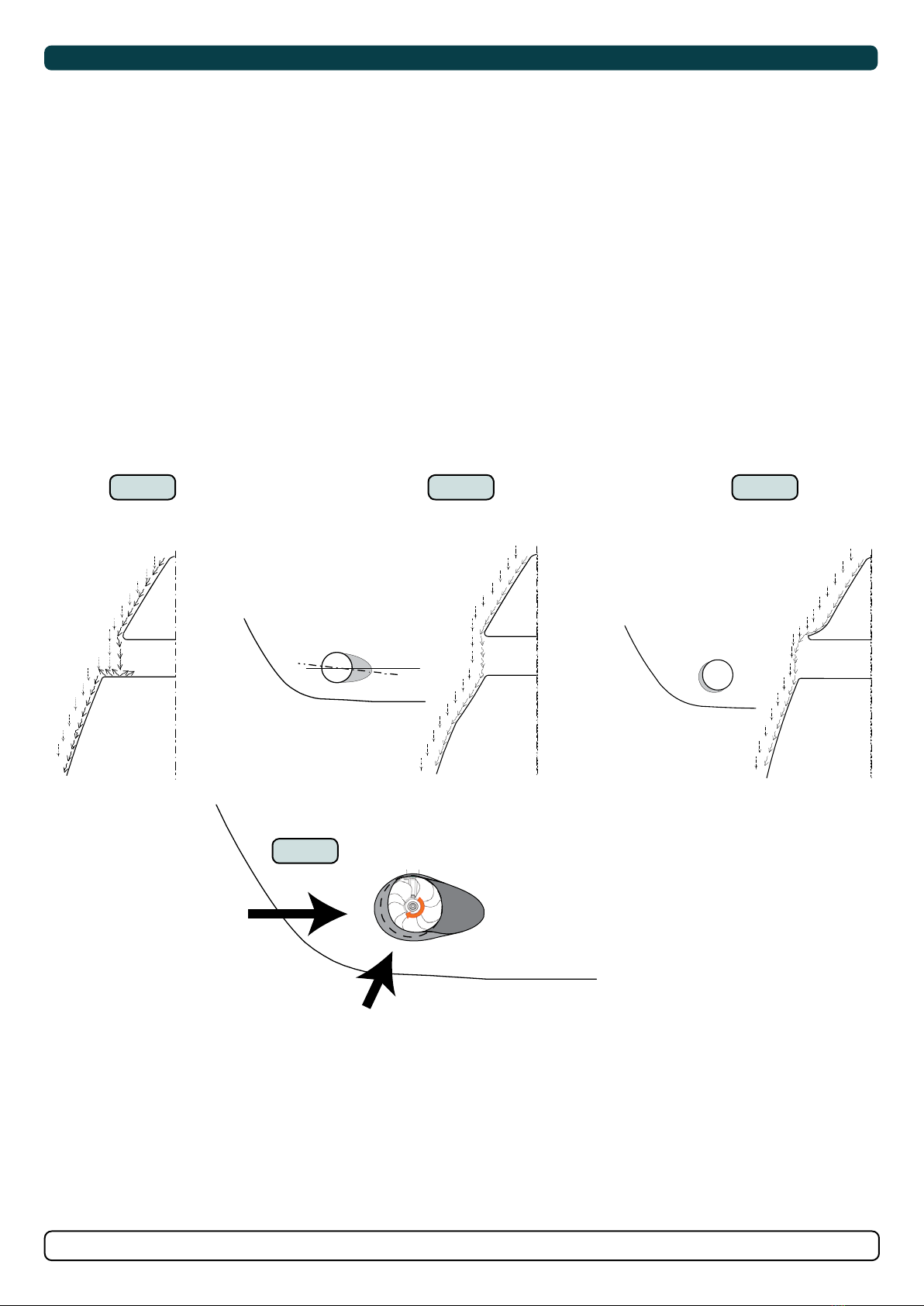
- Beware of keeping installation within advised measurements. No part of the propeller or gear house must be outside the tunnel.
• Do not install the thruster in a position where you need to cut a stiffener/ stringer/ support that may jeopardise the hull integrity without checking
with the boat builder this can be done safely.
• The electro motor, components and cables must be mounted so they remain dry at all times.
• We advise painting the gear house and propellers with anti-fouling. (NB: Do not paint the anodes, sealing, rubber fi ttings or propeller shafts)
• Do not fi nish the inside of the tunnel with a layer of gel-coat/ topcoat or similar. There is only room for a thin coat of primer and two layers of anti-
fouling between the tunnel and the props.
• Don’t install the electro motor close to easily flammable objects or equipment as it will reach over 100°C before the temperature switch is activated.
• Do not store items close to the thruster motor. Any loose items near the thruster motor is a potential fi re hazard and can cause undesired short-
circuiting.
• Do not lift it by internal cable connections, main terminals.
• The thruster power supply circuit must include the recommended sized fuse and a battery isolation switch.
The installer must read this document to ensure necessary familiarity with the product before installation.
Instructions in this document cannot be guaranteed to comply with all international and national regulations. It is the responsibility of the
installer to follow all applicable international and national regulations when installing Sleipner products.
The recommendations given in this document are guidelines ONLY, and Sleipner strongly recommends that advice is obtained from a person
familiar with the particular vessel and applicable regulations.
This document contains general installation instructions intended to support experienced installers. If you are not skilled in this type of work,
please contact professional installers for assistance.
If required by local regulation, electrical work must be done by a licensed professional.
Appropriate health and safety procedures must be followed during installation.
Faulty installation of Sleipner products will render all warranties given by Sleipner Motor AS.
MC_0038
Responsibility of the Installer
MC_0426
General Installation Considerations and Precautions for DC Electric Motors
• The electro motor will generate some carbon dust so any storage compartments must be separated from the thruster to prevent nearby items
becoming dusty/ dirty. (NB: IP version motors generate dust but are enclosed.)
Failure to follow the considerations and precautions can cause serious injury,
damage and will render all warranties given by Sleipner Motor as VOID.
MC_0411
MC_0425
General Installation Considerations and Precautions for Thrusters
• Do not install the thruster in a position where you need to cut a stiffener/ stringer/ support that may jeopardise the hull integrity without checking
with the boat builder this can be done safely.
• We advise painting the gear house and propellers with anti-fouling. (NB: Do not paint the anodes, sealing, rubber fi ttings or propeller shafts)
• Do not fi nish the inside of the tunnel with a layer of gel-coat/ topcoat or similar. There is only room for a thin coat of primer and two layers of anti-
fouling between the tunnel and the props.
• Never run the thruster out of water.
• The electro/ hydrulic motor must be handled with care. Do not place down the motor on the drive shaft.

4524 6 12 2 0 21
-
SEP 250 & SEP 300
Failure to follow the considerations and precautions can cause serious injury,
damage and will render all warranties given by Sleipner Motor as VOID.
MC_0411
MC_0105
Considerations and Precautions for S-Link Systems
When installing an S-Link™ system DO NOT connect any other control equipment directly to the S-Link™ bus except original Sleipner S-Link™ products.
In case of connecting third-party equipment, it must always be connected through a Sleipner-supplied interface product.
Any attempt to directly control or connect into the S-Link™ control system without a designated and approved interface will render all warranties and
responsibilities of all of the connected Sleipner products.
If you are interfacing the S-Link™ bus by agreement with Sleipner through a designated Sleipner supplied interface, you are still required to install at
least one original Sleipner control panel to enable efficient troubleshooting if necessary.

5
524 6 12 2 0 21
-
SEP 250 & SEP 300
MC_0126
Thruster Measurements
Measurement
code Measurement description mm inch mm inch
ID Internal tunnel diameter 300 11,81 300 11,81
H Motor Height 490 19,29 457 17,99
W Width 337 13,27 350 13,78
L Length 274 10,79 274 10,79
WD Water Depth 300 11,81 300 11,81
TL Minimum tunnel length 273 10,75 273 10,75
TL (recommended) Recommended tunnel length 333 13,11 333 13,11
T (min) Minimum tunnel wall thickness 10 0,39 10 0,39
T (max) Maximum tunnel wall thickness 12 0,47 12 0,47
*250
24v *300
48v
*Valid for SE & SEP
MG_0075
TL
WD
H
WL
ID
T
Tunnel centre line
Twin Propeller
The gear leg/ propeller(s) must
never extend out of the tunnel
Propeller position will vary
with each thruster model
Failure to follow the considerations and precautions can cause serious injury,
damage and will render all warranties given by Sleipner Motor as VOID.
MC_0411
MC_0105
Considerations and Precautions for S-Link Systems
When installing an S-Link™ system DO NOT connect any other control equipment directly to the S-Link™ bus except original Sleipner S-Link™ products.
In case of connecting third-party equipment, it must always be connected through a Sleipner-supplied interface product.
Any attempt to directly control or connect into the S-Link™ control system without a designated and approved interface will render all warranties and
responsibilities of all of the connected Sleipner products.
If you are interfacing the S-Link™ bus by agreement with Sleipner through a designated Sleipner supplied interface, you are still required to install at
least one original Sleipner control panel to enable efficient troubleshooting if necessary.

6524 6 12 2 0 21
-
SEP 250 & SEP 300
MC_0140
Thruster Specifi cations
Description * 250 * 300
Available DC System (v) 24v 24v & 48v
Thrust 12v or 24v (kg * lbs) 300 kg * 661 lbs 350 kg * 749 lbs
Thrust 10.5v or 21v (kg * lbs) 250 kg * 551 lbs 300 kg * 661 lbs
Typical Boat Size (m * ft) 18m - 25m * 60ft - 84ft 22m - 30m * 72ft - 100ft
Propulsion System Twin Counter Rotating Twin Counter Rotating
Power (kw * Hp) 11.4kw * 15.5hp 15kw * 20hp
Weight (kg * lbs) 70kg * 154lbs 73kg * 160lbs
*Valid for SE / SE IP & SEP / SEP IP
MC_0052
Technical Specifi cations
Motor: Custom made reversible DC-motor.
Gear house: Seawater resistant bronze. Ball-bearing at propeller shaft and a combination of ball bearing and slide bearing at drive shaft.
(Pre-fi lled and sealed for life)
Motor bracket: Seawater resistant aluminium, galvanically insulated from the motor..
Tunnel: Cross spun with rowing G.R.P tunnel
Steel & aluminium tunnels available at request.
Propeller: 5-blade skewback “Q-prop” propeller, fi breglass reinforced composite.
Batteries: Minimum recommended battery capacity (cold crank capacity by DIN/SAE standard)
Contact a battery supplier for more information.
Max. use: 2 - 3 min. duty cycle at 20°C
Safety features: - Electronic time-lapse device protects against sudden change of drive direction.
- The electric thermal cut-off switch in electro motor protects against overheating (auto-reset when electro motor cools down).
- Flexible coupling between electro-motor and drive shaft protects electro motor and gear system if propeller jams.
- Original Sleipner panels shut off automatically 6 minutes after last use. This interval can be adjusted in 5 min steps up to 60
minutes or turned off completely.
- Original Sleipner panels use child-safe double ON buttons.
- An integrated microprocessor monitors solenoids, reduce wear and risk of solenoid lock-in.
- Auto-stop of the thruster occurs when an undesirable solenoid lock-in occurs or when continuous operation cut-off timer
exceeds 3 minutes.
MC_0055
Proportional Technical Specifi cations
Safety features: - The PPC Speed Control unit will turn off motor power each time the main solenoids are activated. This removes any possibility for
solenoid lock-in. Any fault in the main solenoids will give feedback to the panel and turn off power to the electric motor.

7
524 6 12 2 0 21
-
SEP 250 & SEP 300
MC_0140
Thruster Specifi cations
Description * 250 * 300
Available DC System (v) 24v 24v & 48v
Thrust 12v or 24v (kg * lbs) 300 kg * 661 lbs 350 kg * 749 lbs
Thrust 10.5v or 21v (kg * lbs) 250 kg * 551 lbs 300 kg * 661 lbs
Typical Boat Size (m * ft) 18m - 25m * 60ft - 84ft 22m - 30m * 72ft - 100ft
Propulsion System Twin Counter Rotating Twin Counter Rotating
Power (kw * Hp) 11.4kw * 15.5hp 15kw * 20hp
Weight (kg * lbs) 70kg * 154lbs 73kg * 160lbs
*Valid for SE / SE IP & SEP / SEP IP
important
MG_0001
A
B
Pivot
point
1
Ø
2
Lowered rotation power performance
Stronger rotation power performance
min 1/4
Ø
(Recommended)
min 1/4
Ø
(Recommended)
WD
Water line
Positioning of the tunnel / thruster MC_0003
Aim to install the thruster as far forward as possible (1)
Due to the leverage effect around the boats’ pivot point. The distance difference from the boat pivots’ point to the thruster will determine the amount
of real rotation power for the boat.
Aim to install the thruster as deep as possible under the waterline (2)
Deeper installations prevent air from being sucked into the tunnel from the surface, resulting in reduced thrust performance and increase noise levels
during operation. Deeper installations increase water pressure for maximum effi ciency from the thruster.
The centre of the tunnel should be a minimum of 1 x the tunnel diameter below the waterline. The installer must make evaluations based on thruster
performance, boat type and operating conditions. As a general recommendation, the position of the tunnel should not be a minimum of 1/4 of the
diameter of the tunnel from the boat keel. (NB: This can be overlooked depending on the installation methods defi ned in this manual.)

8524 6 12 2 0 21
-
SEP 250 & SEP 300
1
2
3
4 65
MG_0048
Increase tunnel length to protect
the propeller from water forces
when high-speed cruising.
Water
Forces
Increase tunnel length to
prevent a circular water vacuum
cavity between the propeller and
the hull of the boat.
STANDARD USE FLAT BOTTOM HULL HIGH-SPEED OPERATION
Do not allow the variable length of the tunnel walls to vary in length
excessively.
EG. the top tunnel wall is x 4 longer than the bottom wall.
Cavitation
Water flow must have
space to "straighten"
itself for best
performance.
The gear leg/ propeller(s) must
never extend out of the tunnel
Optimal tunnel length
Achieving the correct tunnel length depends on many factors from the hull type, operation and environmental conditions.
Tunnels should avoid being longer than 4 x the tunnel diameter as this will reduce thruster performance. (NB: Installing long length tunnels can flex/
bend over time and may require additional support. Consult with a naval architect.)
1. Do not allow the variable length of the tunnel walls to vary in length excessively.
EG. The top tunnel wall is x 4 longer than the bottom wall.
2. If the tunnel is too long, the friction inside will reduce the water speed and thereby the thrust.
3. If the tunnel is too short (typically only in the bottom section of the tunnel) cavitation problems can occur as water flow will not be able to
“straighten” itself before reaching the propeller. This cavitation will reduce performance and increase noise during operation.
Thruster within the tunnel
It is important the propellers and the lower unit/ gear leg must be entirely inside the thruster tunnel. Propellers that protrude from the tunnel will not
perform as intended.
4. Standard Use
Tunnel length must be long enough to ensure the propellers are not extruding the tunnel.
5. Flat Bottom Hull
Tunnel lengths must be longer than the standard measurement outlined within the manual to ensure a circular vacuum is not created between the
thruster and the bottom of the boat.
6. High-Speed Boats
Tunnel lengths must be increased to protect the propeller from damage when crashing against the water surface during high-speed cruising. (NB:
This can include the length of a spoiler)
MC_0003
Tunnel Length

9
524 6 12 2 0 21
-
SEP 250 & SEP 300
MG_0004
Min
Pos. B
Pos. A
1
1
2
3
4 65
MG_0048
Increase tunnel length to protect
the propeller from water forces
when high-speed cruising.
Water
Forces
Increase tunnel length to
prevent a circular water vacuum
cavity between the propeller and
the hull of the boat.
STANDARD USE FLAT BOTTOM HULL HIGH-SPEED OPERATION
Do not allow the variable length of the tunnel walls to vary in length
excessively.
EG. the top tunnel wall is x 4 longer than the bottom wall.
Cavitation
Water flow must have
space to "straighten"
itself for best
performance.
The gear leg/ propeller(s) must
never extend out of the tunnel
Tunnel installation in Sailboats
Some sail boats have a flat bottom and shallow draft in the bow section. This can make installing the thruster as far forward from the boats main pivot
point diffi cult. (Fig. 1).
However, it is possible to install a tunnel thruster in most sail boats, even when the hull does not directly support the fi tting of a tunnel.
Instead fi t the tunnel halfway into the underneath section of the existing hull. Strengthen it with a deflector/ spoiler directing the water flow around
the tunnel. This will allow installation of the thruster in the proper position on the boat, maintaining the reliability and space advantages of the tunnel
thruster.
This installation is being used by some of the world’s largest sail boat builders and has proven to give little to no speed loss during normal cruising.
This can also be an installation method for flat bottomed barges to avoid extremely long tunnels and large oval tunnel openings in the hull.
MC_0003

10 524 6 12 2 0 21
-
SEP 250 & SEP 300
MG_0003
High water force
while underway
High water force
while underway
from wave contact
1 2 3
4
Water Deflection MC_0003
1. A possible problem in sail boats or fast powerboats is that a non-rounded surface can generate drag from the back face of the tunnel, as it creates
a “flat” area facing the flow of water.
This problem can be solved in two different ways, depending on what is possible or easier to perform.
2. The best solution which generally reduces the most drag is to make a recess in the hull at the back of the tunnel. As the back face is removed
water can flow freely past the tunnel entry. The depth and shape of this recess will depend on the boat and the angle facing up/ down aft of the
tunnel insert. Normally it is angled slightly down because of the water flow on this area.
3. Making a deflector/ spoiler in front and underneath the tunnel can also reduce damage to the thruster and drag. The deflector/ spoiler will push
the water flow out from the hull so water can pass by the back face of the tunnel. The shape and size of this deflector/ spoiler will depend on the
hull shape. The easiest way of making the deflector/ spoiler is to retain a part of the lower forward area of the tunnel while installing the tube. Use
this area as support to mould a soft curve/spoiler shape from the hull.
4. The thruster propeller can spin (passively) producing noise while sailing or cruising as water is forced through the tunnel. Water-flow directed
through the tunnel at high speeds, during turning or as the boat bumps waves while underway can also damage the thruster.
(NB: As a rule, you should not see the back face of the tunnel when standing directly in front of the boat looking aft.)

11
524 6 12 2 0 21
-
SEP 250 & SEP 300
MG_0002
R = 0,1 x D (10%)
D
12
3
Angled tunnel ends for
steel/ aluminium hulls
Cavitation
MG_0003
High water force
while underway
High water force
while underway
from wave contact
1 2 3
4
Tunnel Ends MC_0003
Rounded tunnel ends will maximise thrust and minimise noise and cavitation.
For best performance round the tunnel connection to the hull-side as much as possible. The minimum rounding has a radius of 10% of the diameter of
the tunnel.
Signifi cant advantages of a rounded tunnel over a sharp tunnel to hull connections are:
1. A rounded tunnel end will prevent the creation of turbulence/ cavitation created from a sharp tunnel end when water passes by the tunnel.
- The turbulence/ cavitation will block the outer area of the tunnel and thereby reduces the effective tunnel diameter and thrust.
- Turbulence/ cavitation on the propeller will lessen the thrusters performance and create excess noise.
2. For steel/ aluminium hulls angled tunnel ends also offer similar performance as a rounded connection.
3. A rounded tunnel end makes the thruster draw water from along the hull-side, creating a vacuum that will suck the boat sideways and thereby give
additional thrust.
- With a sharp tunnel end, the thruster will be unable to take water from along the hull-side, and you will not gain the desired vacuum and
additional thrust. This “free” extra thrust in optimal installations be 30 - 40% of the total thrust.
(NB: A Side-power thruster propeller does not produce cavitation at working speed. Therefore, any cavitation and cavitation noise in the tunnel will
be caused during improper tunnel installation.)

12 524 6 12 2 0 21
-
SEP 250 & SEP 300
MG_0005
R
D
1 2
34
6
5
8 x layers of fiberglass
and resin
8 x layers of fiberglass
and resin
MG_0006
R = D x 0,1
R = D x 0,1
Dx0,1-0,15
Dx0,1-0,15
D
Layers of
fiberglass
and resin
Layers of
fiberglass
and resin
*Fiberglass
Hull
*Steel/
Aluminium
Hull
Hull
Hull
Hull
Tunnel
Tunnel
Tunnel
Welding
Layers of
fiberglass
and resin
Additional Layers of
fiberglass and resin
Additional Layers of
fiberglass and resin
Hull
1 3
4
2
Tunnel Installation
1. Find the position in the boat considering the information earlier in this manual and the applicable measurements for the thruster model you are
installing. Mark the centre of the tunnel on both sides of the hull. Drill a hole horizontally at these marks.
2. Mark the circle for the tunnel opening (outside diameter of the tunnel) and cut the hole.
3. Grind off the gel coat to the “real fi breglass” area 12cm around the hole on both inside and outside the hull to cast the tunnel to the hull (Fig. 3).
4. Insert the tunnel and mark its shape to fi t the hull. (NB: if you are installing with a deflector/ spoiler, leave a part of the tunnel in the front and
underside of the tunnel that will cover the back face.)
5. Cut the tunnel ends to the desired shape and lightly sand its surface. Clean the area with acetone or similar where you are going to apply
fi breglass. (NB: Do not cast or add fi breglass to the area were the thruster will be placed.)
6. Cast the tunnel to the inside of the hull, use at least eight layers of 300g fi breglass and resin, preferably alternating mat and rowing types of
fi breglass. To round the tunnel ends to a 10% radius make further layers inside to preserve the desired hull thickness.
(NB: Ensure gaps between the tunnel and the hull are completely fi lled with resin/ fi breglass. In areas where you can not access to make
layers of resin/ fi breglass, a resin/ fi breglass mixture must be used in that area.)
MC_0003
IMPORTANT
We recommend that a professional does the fi breglass, steel or aluminium fi tting of the tunnel. These instructions are only general
instructions and do not explain in any way the details of fi breglass work. Problems caused by faulty installation of the tunnel, are the
installers full responsibility.

13
524 6 12 2 0 21
-
SEP 250 & SEP 300
MG_0005
R
D
1 2
34
6
5
8 x layers of fiberglass
and resin
8 x layers of fiberglass
and resin
MG_0006
R = D x 0,1
R = D x 0,1
Dx0,1-0,15
Dx0,1-0,15
D
Layers of
fiberglass
and resin
Layers of
fiberglass
and resin
*Fiberglass
Hull
*Steel/
Aluminium
Hull
Hull
Hull
Hull
Tunnel
Tunnel
Tunnel
Welding
Layers of
fiberglass
and resin
Additional Layers of
fiberglass and resin
Additional Layers of
fiberglass and resin
Hull
1 3
4
2
IMPORTANT
Avoid all casting where the motor-bracket is to be placed, as this will cause misfi t and possible failure to the gear house.
Tunnel Installation
With tunnel installed and cast.
1. Round the edges with a radius of 10% of the tunnel diameter.
2. For steel/ aluminium hulls make a slope with a length of 10-15% of the tunnel diameter.
(NB: If this is not possible, round the tunnel end as much as possible.)
3. Additionally cast two layers on the outside of the tunnel/ hull in a 10cm area
4. Follow the same method if making the deflector/ spoiler.
You must apply gel coat to areas you have grounded/ moulded to make waterproof. These areas allow water access to the hull which is typically not
waterproof without these applications outside. (NB: All original Side-Power tunnels are fully waterproof when delivered except in the areas where
you have cut and bonded it to the hull.)
MC_0003

14 524 6 12 2 0 21
-
SEP 250 & SEP 300
For Stern Thruster installation please refer to the supplied manual in your Sleipner product delivery
Stern Thruster
SLEIPNER AS
P.O. Box 519
N-1612 Fredrikstad
Norway
www.sleipnergroup.com
DOCUMENT ID:
REVISION:
DATE:
LANGUAGE:
Installation Guide
Stern Tunnel Installation MC_0003

15
524 6 12 2 0 21
-
SEP 250 & SEP 300
For Stern Thruster installation please refer to the supplied manual in your Sleipner product delivery
Stern Thruster
SLEIPNER AS
P.O. Box 519
N-1612 Fredrikstad
Norway
www.sleipnergroup.com
DOCUMENT ID:
REVISION:
DATE:
LANGUAGE:
Installation Guide
Stern Tunnel Installation MC_0003
MC_0001
Gear Leg & Motor Bracket Installation
!Please refer to the graphic for special considerations relating to your model !
1. Mark the tunnel centreline and the boat’s centreline. (NB: Install the gear leg and propeller as shown above for the thrust direction to correspond
with the control panel. Position gear leg with the P-mark facing port and the S-mark facing starboard.)
2. Use the gasket or template (recommended) to mark the hole centres and double-check the measurements. The centre hole MUST be placed
using the boat centreline as shown above. (NB: All holes must be in-line with the tunnels’ centreline for correct installation, clearance between
the propeller and the tunnel is minimal.)
3. Smooth the surface of the tunnel. A rough surface will cause possible failure/movement of the gear leg. The motor bracket must rest steadily on
the tunnel.
4. Drill the main centre hole followed by the two screw-holes.
5. Place the gear leg (without the propeller) with the gasket on inside the tunnel. Place the propeller on the gear leg to ensure it is centred and
rotates freely with the same clearance from each blade to the tunnel wall. Place top motor bracket to measure the drive shaft has come through
the motor bracket at the correct height. Remove the gear leg and propeller for fi nal installation.
6. Apply appropriate sealant to both sides of the gasket and place on the gear leg. Place the gear leg in the tunnel (without the propeller).
7. Install the top motor bracket and gear leg gently together. Use appropriate sealant to ensure that no leakages occur. (NB: See your sealant data
sheet for the correct application process.)
8. Fasten the gear leg and the motor bracket with the bolts provided. Fasten to torque as shown above.
MG_0057
PORT STARBOARD
S
P
Tunnel
centre line
Boats
centre line
Bow
Stern
1
STARBOARDPORT
BOW
Tunnel
centre line
Boats
centre line
B
ØC
ØA
Measurement
Description
ØA
B
ØC
mm inch
52 2.05
48 1.89
12 0.43
SE*P 250
SE*P 300
BOW
Gasket
Ensure propeller
turns without
obstruction
5BOW
BOW
BOW
Apply MS Polymer
sealant or equal to
both sides of the
gasket
Motor bracket
IMPORTANT
Do not apply sealant to
the holes.
6 - 7
2 - 4
8
*P- Propositional
FASTEN
33 Nm
24 lb/ft

16 524 6 12 2 0 21
-
SEP 250 & SEP 300
MG_0033
Drive Pin
Propeller
Washer
Lock Nut
Anode
Anode Holding
Screw
Apply Loctite 243 or similar
Anti-fouling
Propeller Installation MC_0264
!Please refer to the graphic for special considerations relating to your model !
1. Centre the drive pin and Insert the propeller onto the shaft spine. Rotate the propeller until the drive pin aligns with the internal slot in the
propeller.
2. Insert the washer to the end of the shaft spline. Tighten with the propeller lock-nut.
3. Insert the anode to the end of the propeller and tighten the anode holding screw. Apply a thread glue (Loctite 243 or similar) to ensure that the
anode holding screw does not unscrew itself from during the rotation of the propeller.
4. Apply anti-fouling to the gear leg and propeller. Do not apply anti-fouling to any rubber elements of the gear leg or anodes.
IMPORTANT
For twin counter-rotating gear legs, propellers are marked with P (Port) and S (starboard) and must be installed appropriately.

17
524 6 12 2 0 21
-
SEP 250 & SEP 300
Motor Installation
1. Install the motor onto the motor bracket ensuring the couplings are engaged together correctly (top and bottom). (NB: The motor can be placed
in all directions on the motor bracket. However, ensure the cable terminals are accessible for electrical installation later.)
2. If you are installing the motor at an angle of more than 30 degrees off vertical, the motor will require separate/ additional support. (NB: Do not
position supports on the motors top cap.)
3. Fasten the bolts holding the motor to the motor bracket with the above torque.
4. Check the drive shafts are engaged by rotating the propeller. (NB: Rotating the propellers can be hard due to the gear reduction and the motor,
however the propeller must be able to rotate via hand power.)
MC_0019
!Please refer to the graphic for special considerations relating to your model !
IMPORTANT
The thruster motor assembly must be protected using suitable covering to avoid dust/debris ingress from fabrication/maintenance/shipbuilding
operations. On completion of operations, the cover must be removed before operating the thruster.
MG_0058
1
2
3
IMPORTANT
Do not position support
on the motor cap.
FASTEN
(33 Nm)
(24 lb/ft)
Motor support
Motor
Cap
> 30°
Holding Key
IMPORTANT
Ensure the holding key
and coupling are
aligned when fitted
MG_0033
Drive Pin
Propeller
Washer
Lock Nut
Anode
Anode Holding
Screw
Apply Loctite 243 or similar
Anti-fouling

18 524 6 12 2 0 21
-
SEP 250 & SEP 300
MC_0035
Thruster Electrical Installation
!Please refer to the graphic for special considerations relating to your model !
WARNING
Check the following with the main switch is set to off :
After all electrical connections have been completed check with an ohm meter that there is no electrical connection between
1. electro-motor flange and the positive terminal on the motor
2. electro-motor flange and the battery negative terminal on the motor
If unsure contact skilled personnel.
1. Information of electrical table. see next page
- All power cable lengths represent the total length of the combined (+) and (-) cables.
- Battery capacity is stated as minimum cold crank capacity, (CCA).
- Use slow blow rated fuses to hold stated Amp-Draw for min. 5 minutes.
- Consider the AMP hours (Ah) for your specifi c duty cycle.
2. Use appropriate sized cables and batteries with high cranking capacity to feed the thruster. The actual voltage at the motor while running the
thruster decides the motors output RPM and thrust. Use larger cables and stronger batteries for better results.
- See electrical specifi cations for advised minimum cables and batteries (CCA).
3. Connect the battery supply to the control unit (PPC).
- Install a main manual/ automatic switch from the positive lead terminal on the battery PPC unit). The main switch must be accessible to turn
off the thruster independently from the rest of the electrical operation of the vessel when not on-board or in emergencies. (NB: It is advised
to install a fuse on the positive cable for protection against short-circuiting of the main cables. The fuse should ensure no voltage
decrease, slow-blow and sized to take the amperage draw for at least 5 minutes.)
- A circuit breaker can be used instead of the fuse and main power switch If the functionality is the same.
(NB: For Ignition Protected installations remember to use ignition protected fuses and switches if fi tted in areas that require this feature.
Ensure to follow your national regulations)
5. Cable lugs must have adequate electrical and mechanical isolation and fi tted with cable lug covers.
6. Fasten cables to the required torque.
MG_0021
PPC
Battery
12V or
24V
Proportional Power Controller PPC
Fuse
Manual or automatic
Main switch
4x
Min
200mm
Min
100mm
Min
100mm
Min 150mm
Fixed multi cable 5m/ 6 1280-05M
Motor
S-link control cables
IMPORTANT
The Proportional Power Controller is a bulkhead (wall)
mounted unit and must be installed in a dry and
well-ventilated compartment. The unit also requires a
200mm minimum head clearance, 150mm minimum
bottom clearance and a 100mm minimum clearance
surrounding its remaining outer casing.
Hold in place
for securing
the end nut.
(M8) Nut
Tighten to *max
13 Nm (9.59 lb/ft)
(M10) Nut
Tighten to *max
23 Nm (16.96 lb/ft)
Spring
washer
Lugs
IMPORTANT
Do NOT use washers between lugs, this
causes overheating and fire. Spring
washers must be placed in the outer
position before tightening nut.
Multi-lug configuration
Ensure lug faces are
back to back.
Spring
washer
NutNut
Lugs
*48v for 300 size thruster

19
524 6 12 2 0 21
-
SEP 250 & SEP 300
Electrical Specifi cations MC_0044
*Valid for DC motors
Model Size System
Voltage
Nominal
current
draw
Min. battery
CCA Rec. fuse
<7m total + & - 7-14m total + & - 15-21m total + & - 22-28m total + & - 28-35m total + & - 36-45m total + & -
Min. Rec. Min. Rec. Min. Rec. Min. Rec. Min. Rec. Min. Rec.
*20/110S 12 V 150 A
DIN: 200
SAE: 380
EN: 330
ANL 150
mm2 25 35 35 50 50 70 70 95 95 95 120 2 x 70
AWG 3 2 2 1/0 1/0 2/0 2/0 3/0 3/0 3/0 2 x 4/0 2 x 2/0
*25/110S 12 V 200 A
DIN: 200
SAE: 380
EN: 330
ANL 150
mm2 25 35 50 50 70 70 95 95 120 120 2 x 70 2 x 70
AWG 3 2 1/0 1/0 2/0 2/0 3/0 3/0 4/0 4/0 2 x 2/0 2 x 2/0
*30/125S
*30/140 12 V 245 A
DIN: 200
SAE: 380
EN: 330
ANL 150
mm2 35 50 50 70 70 95 95 120 120 2 x 70 2 x 70 2 x 95
AWG 2 1/0 1/0 2/0 2/0 3/0 3/0 4/0 4/0 2 x 2/0 2 x 2/0 2 x 3/0
*40/125S
*40/140 12 V 315 A
DIN: 300
SAE: 570
EN: 520
ANL 250
mm2 35 50 70 95 95 120 120 2 x 70 2 x 95 2 x 95 2 x 120 2x 120
AWG 2 1/0 2/0 3/0 3/0 4/0 4/0 2 x 2/0 2 x 3/0 2 x 3/0 2 x 4/0 2 x 4/0
*50/140S
12 V 370 A
DIN: 350
SAE: 665
EN: 600
ANL 325
mm2 50 50 70 95 120 2 x 70 2 x 70 2 x 95 2 x 95 2 x 120 2 x 120 2 x 120
AWG 1/0 1/0 2/0 3/0 4/0 2 x 2/0 2 x 2/0 2 x 3/0 2 x 3/0 2 x 4/0 2 x 4/0 2 x 4/0
24 V 170 A
DIN: 175
SAE :332
EN: 280
ANL 150
mm2 25 25 25 35 35 50 35 50 50 70 70 70
AWG 3 3 3 2 2 1/0 2 1/0 1/0 2/0 2/0 2/0
*60/185S
*60/140
12 V 370 A
DIN: 350
SAE: 665
EN: 600
ANL 325
mm2 50 50 70 95 120 2 x 70 2 x 70 2 x 95 2 x 95 2 x 120 2 x 120 2 x 120
AWG 1/0 1/0 2/0 3/0 4/0 2 x 2/0 2 x 2/0 2 x 3/0 2 x 3/0 2 x 4/0 2 x 4/0 2 x 4/0
24 V 170 A
DIN: 175
SAE: 332
EN: 280
ANL 150
mm2 25 25 25 35 35 50 35 50 50 70 70 70
AWG 3 3 3 2 2 1/0 2 1/0 1/0 2/0 2/0 2/0
*80/185T
12 V 530 A
DIN: 550
SAE: 1045
EN: 940
ANL 400
mm2 70 70 120 2 x 70 2 x 95 2 x 95 2 x 120 2x 120 2 x 120
NA NA NA
AWG 2/0 2/0 4/0 2 x 2/0 2 x 3/0 2 x 3/0 2 x 4/0 2 x 4/0 2 x 4/0
24 V 280 A
DIN: 300
SAE:570
EN: 520
ANL 250
mm2 35 35 35 50 50 70 70 95 95 120 120 2 x 95
AWG 2 2 2 1/0 1/0 2/0 2/0 3/0 3/0 4/0 4/0 2 x 3/0
*100/185T
12 V 740 A
DIN: 750
SAE: 1425
EN: 1320
ANL 500
mm2 95 95 2 x 70 2 x 95 2 x 120
NA NA NA NA NA NA NA
AWG 3/0 3/0 2 x 2/0 2 x 3/0 2 x 4/0
24 V 340 A
DIN: 400
SAE: 760
EN: 680
ANL 325
mm2 50 50 50 70 70 95 95 120 120 2 x 95 2 x 95 2 x 120
AWG 1/0 1/0 1/0 2/0 2/0 3/0 3/0 4/0 4/0 2 x 3/0 2 x 3/0 2 x 4/0
*120/215T 24V 420 A
DIN: 450
SAE: 855
EN: 760
ANL 325
mm2 70 70 70 70 70 95 95 120 120 2 x 70 2 x 70 2 x 95
AWG 2/0 2/0 2/0 2/0 2/0 3/0 3/0 4/0 4/0 2 x 2/0 2 x 2/0 2 x 3/0
*130/250T
12V 800 A
DIN: 750
SAE: 760
EN: 680
ANL 500
mm2 95 95 2 x 95 2 x 95 2 x 120 2 x 120
NA NA NA NA NA NA
AWG 3/0 3/0 2 x 2/0 2 x 3/0 2 x 4/0 2 x 4/0
24V 350 A
DIN: 400
SAE: 760
EN: 680
ANL 325
mm2 50 50 50 70 70 95 95 120 120 2 x 70 2 x 95 2 x 95
AWG 2 1/0 1/0 2/0 2/0 3/0 3/0 4/0 4/0 2 x 2/0 2 x 3/0 2 x 3/0
*150/215T 24V 610 A
DIN: 560
SAE: 1064
EN: 940
ANL 500
mm2 70 70 95 95 120 120 2 x 70 2 x 95 2 x 95 2 x 120 2 x 120 2 x 120
2 2/0 2/0 3/0 3/0 4/0 4/0 2 x 2/0 2 x 3/0 2 x 3/0 2 x 4/0 2 x 4/0 2 x 4/0
*170/250 24V 550 A
DIN: 560
SAE: 1064
EN: 940
ANL 400
mm2 70 70 70 95 95 120 120 2 x 95 2 x 95 2 x 95 2 x 120 2 x 120
AWG 2/0 2/0 2/0 3/0 3/0 4/0 4/0 2 x 3/0 2 x 3/0 2 x 3/0 2 x 4/0 2 x 4/0
*210/250 24V 500 A
DIN: 560
SAE: 1330
EN: 940
ANL 400
mm2 70 70 70 95 95 120 120 2 x 70 2 x 70 2 x 95 2 x 95 2 x 120
AWG 2/0 2/0 2/0 3/0 3/0 4/0 4/0 2 x 2/0 2 x 2/0 2 x 3/0 2 x 3/0 2 x 4/0
*250/300 24V 610-670 A
DIN: 700
SAE: 1330
EN: 1170
ANL 500
mm2 70 70 95 120 120 2 x 95 2 x 95 2 x 95 2 x 95 2 x 120 2 x 120 2 x 120
AWG 2/0 2/0 3/0 4/0 4/0 2 x 3/0 2 x 3/0 2 x 3/0 2 x 3/0 2 x 4/0 2 x 4/0 2 x 4/0
*300/300
24*2 400-450A
(48V)
DIN: 400
SAE: 760
EN: 680
ANL 325
mm2 50 70 50 70 70 95 95 120 120 120 140
NA
48V AWG 1/0 2/0 1/0 2/0 2/0 3/0 3/0 4/0 4/0 4/0 4/0
MC_0035
Thruster Electrical Installation
!Please refer to the graphic for special considerations relating to your model !
WARNING
Check the following with the main switch is set to off :
After all electrical connections have been completed check with an ohm meter that there is no electrical connection between
1. electro-motor flange and the positive terminal on the motor
2. electro-motor flange and the battery negative terminal on the motor
If unsure contact skilled personnel.
1. Information of electrical table. see next page
- All power cable lengths represent the total length of the combined (+) and (-) cables.
- Battery capacity is stated as minimum cold crank capacity, (CCA).
- Use slow blow rated fuses to hold stated Amp-Draw for min. 5 minutes.
- Consider the AMP hours (Ah) for your specifi c duty cycle.
2. Use appropriate sized cables and batteries with high cranking capacity to feed the thruster. The actual voltage at the motor while running the
thruster decides the motors output RPM and thrust. Use larger cables and stronger batteries for better results.
- See electrical specifi cations for advised minimum cables and batteries (CCA).
3. Connect the battery supply to the control unit (PPC).
- Install a main manual/ automatic switch from the positive lead terminal on the battery PPC unit). The main switch must be accessible to turn
off the thruster independently from the rest of the electrical operation of the vessel when not on-board or in emergencies. (NB: It is advised
to install a fuse on the positive cable for protection against short-circuiting of the main cables. The fuse should ensure no voltage
decrease, slow-blow and sized to take the amperage draw for at least 5 minutes.)
- A circuit breaker can be used instead of the fuse and main power switch If the functionality is the same.
(NB: For Ignition Protected installations remember to use ignition protected fuses and switches if fi tted in areas that require this feature.
Ensure to follow your national regulations)
5. Cable lugs must have adequate electrical and mechanical isolation and fi tted with cable lug covers.
6. Fasten cables to the required torque.

20 524 6 12 2 0 21
-
SEP 250 & SEP 300
MG_0062
Technical Wiring Diagram
A1
A2
D2
NTC
Thruster motor
D1
1
2
3
4
5
6
7
8
To PPC
B+
To PPC
M-
Multi cable to PPC
grey
blue
white
redpink
(Opt.)
8-Way connector
C
C
red or red-brown
This manual suits for next models
1
Table of contents
Other Sleipner Boating Equipment manuals

Sleipner
Sleipner Side-Power ESPE 600 User manual

Sleipner
Sleipner MIDI 202 User manual

Sleipner
Sleipner SX35POD User manual

Sleipner
Sleipner SX35POD User manual

Sleipner
Sleipner SXP35 PRO User manual

Sleipner
Sleipner SH1000 User manual

Sleipner
Sleipner 86-08950 User manual

Sleipner
Sleipner MAXI 31 User manual
Popular Boating Equipment manuals by other brands

Harken
Harken Performa 20.2 PTP Installation and maintenance manual

Golden
Golden JS-1500R installation manual

Boatasy
Boatasy Hooklinker User instruction manual

Classic Accessories
Classic Accessories DryGuard 20-089-092401-11 instructions

Garelick
Garelick 31900 Assembly instructions

Velocitek
Velocitek SC-1 Reference manual