WattNode WNC-3Y-208-MB User manual

WattNode®Modbus
Installation and Operation Manual
●WNC-3Y-208-MB
●WNC-3Y-400-MB
●WNC-3Y-480-MB
●WNC-3Y-600 -MB
●WNC-3D-240-MB
●WNC-3D-400-MB
●WNC-3D-480-MB
http://www.ccontrolsys.com
Continental Control Systems LLC
Rev 1.16 c
(M7)

2
Information in this document is subject to change without notice.
©2008-2011 Continental Control Systems, LLC. All rights reserved.
Printed in the United States of America.
Document Number: WNC-MB-1.16c
Firmware Version: 16
Revision Date: January 28, 2011
Continental Control Systems, LLC.
3131 Indian Rd., Suite A
Boulder, CO 80301
(303) 444-7422
FAX: (303) 444-2903
E-mail: techsupport@ccontrolsys.com
Web: http://www.ccontrolsys.com
WattNode is a registered trademark of Continental Control Systems, LLC.
FCC Information
This equipment has been tested and complies with the limits for a Class B digital device, pursu-
ant to part 15 of the FCC Rules. Operation is subject to the following two conditions: (1) This
device may not cause harmful interference, and (2) this device must accept any interference
received, including interference that may cause undesired operation.
The FCC limits are designed to provide reasonable protection against harmful interference in a
residential installation. This equipment generates, uses and can radiate radio frequency energy
and, if not installed and used in accordance with the instructions, may cause harmful interfer-
ence to radio communications. However, there is no guarantee that interference will not occur in
a particular installation. If this equipment does cause harmful interference to radio or television
reception, which can be determined by turning the equipment off and on, the user is encouraged
to try to correct the interference by one or more of the following measures:
●Reorient or relocate the receiving antenna.
●Increase the separation between the equipment and receiver.
●Connect the equipment into an outlet on a circuit different from that to which the receiver is
connected.
●Consult the dealer or an experienced radio/TV technician to help.

Contents 3
Contents
Overview ................................................................................................................................5
Measurements ................................................................................................................................ 5
Communication ............................................................................................................................... 5
Diagnostic LEDs .............................................................................................................................. 5
Options ........................................................................................................................................... 5
Current Transformers....................................................................................................................... 6
Additional Literature......................................................................................................................... 6
Front Label ...................................................................................................................................... 7
Symbols.................................................................................................................................... 8
Installation .............................................................................................................................9
Precautions ..................................................................................................................................... 9
Electrical Service Types ..................................................................................................................10
Single-Phase Two-Wire with Neutral .........................................................................................10
Single-Phase Three-Wire (Mid-Point Neutral) ............................................................................11
Single-Phase Two-Wire without Neutral ....................................................................................12
Three-Phase Four-Wire Wye.....................................................................................................13
Three-Phase Three-Wire Delta Without Neutral.........................................................................14
Three-Phase Four-Wire Delta (Wild Leg) ...................................................................................14
Grounded Leg Service .............................................................................................................14
Mounting........................................................................................................................................15
Selecting Current Transformers ......................................................................................................16
Connecting Current Transformers...................................................................................................17
Circuit Protection............................................................................................................................18
Connecting Voltage Terminals.........................................................................................................19
Setting the Modbus Address ..........................................................................................................19
Baud Rate............................................................................................................................... 20
Connecting Modbus Outputs......................................................................................................... 20
Planning the Modbus Network ................................................................................................ 20
Installation Summary ..................................................................................................................... 22
Wiring ..................................................................................................................................... 22
Installation LED Diagnostics........................................................................................................... 23
Measurement Troubleshooting....................................................................................................... 26
Other Fixed Pattern ................................................................................................................. 26
Modbus Communication Diagnostics ............................................................................................ 28
Operating Instructions.........................................................................................................31
Quick Start.....................................................................................................................................31
WattNode Basic Configuration .................................................................................................31
Verify Operation .......................................................................................................................31
Modbus Communication ............................................................................................................... 32
Modbus Functions .................................................................................................................. 32
Measurement Overview........................................................................................................... 32
Report Slave ID ....................................................................................................................... 33
Modbus Register Lists................................................................................................................... 33
Modbus Register Addressing .................................................................................................. 33
Floating Point and Integer Registers ........................................................................................ 34
Reading and Writing 32 Bit Registers ...................................................................................... 34
Basic Register List - Floating Point .......................................................................................... 35
Basic Register List - Integer..................................................................................................... 35

4
Advanced Register List - Floating Point ................................................................................... 36
Advanced Register List - Integer...............................................................................................37
Configuration Register List ...................................................................................................... 38
Communication Register List................................................................................................... 39
Diagnostic Register List........................................................................................................... 39
Option Information Registers ................................................................................................... 40
Custom Register Map ............................................................................................................. 40
Basic Registers ..............................................................................................................................41
Energy Registers ......................................................................................................................41
Power Registers.......................................................................................................................41
Voltage Registers .................................................................................................................... 42
Frequency ............................................................................................................................... 42
Advanced Registers ...................................................................................................................... 42
Per-Phase Energy Registers .................................................................................................... 42
Positive Energy........................................................................................................................ 42
Negative Energy ...................................................................................................................... 43
Reactive Energy ...................................................................................................................... 43
Apparent Energy ..................................................................................................................... 43
Power Factor........................................................................................................................... 43
Reactive Power ....................................................................................................................... 44
Apparent Power ...................................................................................................................... 44
Current.................................................................................................................................... 45
Demand.................................................................................................................................. 45
IO Pin Options..........................................................................................................................47
Configuration Registers ..................................................................................................................47
Demand Configuration ............................................................................................................ 49
Zeroing Registers .................................................................................................................... 50
IO Pin Options Configuration ....................................................................................................51
Communication Registers...............................................................................................................51
Diagnostic Registers...................................................................................................................... 52
Error Codes................................................................................................................................... 53
Maintenance and Repair................................................................................................................ 55
Specifications ......................................................................................................................56
Models .......................................................................................................................................... 56
Model Options ........................................................................................................................ 56
Accuracy................................................................................................................................. 57
Measurement ................................................................................................................................ 58
Modbus Communication ............................................................................................................... 58
Electrical ....................................................................................................................................... 59
Certifications ................................................................................................................................. 60
Environmental................................................................................................................................ 60
Mechanical.................................................................................................................................... 60
Current Transformers..................................................................................................................... 60
Warranty...............................................................................................................................62
Limitation of Liability ...................................................................................................................... 62

Overview 5
Overview
Congratulations on your purchase of the WattNode®Modbus®watt/watt-hour transducer (meter).
The WattNode meter offers precision energy and power measurements in a compact pack-
age. It enables you to make power and energy measurements within existing electric service
panels avoiding the costly installation of subpanels and associated wiring. It is designed for use
in demand side management (DSM), sub-metering, and energy monitoring applications. The
WattNode meter communicates on an EIA RS-485 two-wire bus using the Modbus protocol.
Models are available for single-phase, three-phase wye, and three-phase delta configurations for
voltages from 120 VAC to 600 VAC at 50 and 60Hz.
Measurements
The WattNode Modbus meter measures the following:
●True RMS Power - Watts (Phase A, Phase B, Phase C, Sum)
●Reactive Power - VARs (Phase A, Phase B, Phase C, Sum)
●Power Factor (Phase A, Phase B, Phase C, Average)
●True RMS Energy - Watthours (Phase A, Phase B, Phase C, Sum)
●Reactive Energy - VAR-hours (Sum)
●AC Frequency
●RMS Voltage (Phase A, Phase B, Phase C)
●RMS Current (Phase A, Phase B, Phase C)
●Demand and Peak Demand
One WattNode Modbus meter can measure up to three different “single-phase two-wire with
neutral” branch circuits from the same service by separately monitoring the phase A, B, and C
values. If necessary, you can use different CTs on the different circuits.
Communication
The WattNode meter uses a half-duplex EIA RS-485 interface for communication. The standard
baud rates are 9,600 and 19,200 baud, and rates from 1,200 to 38,400 baud can be configured.
The meter uses the industry standard Modbus RTU (binary) communication protocol, allowing
up to 127 devices per RS-485 subnet. The WattNode meter can auto-detect RS-485 polarity on
properly biased networks, simplifying installation.
There are numerous low-cost RS-485 interfaces to PCs, using both USB and serial ports. There
are many PC programs and standalone devices for collecting and recording Modbus data.
Diagnostic LEDs
The meter includes three power diagnostic LEDs—one per phase. During normal operation,
these LEDs flash on and off, with the speed of flashing roughly proportional to the power on each
phase. The LEDs flash green for positive power, red for negative power, and yellow for low power
factor. Other conditions are signaled with different LED patterns. See Installation LED Diagnos-
tics (pg 23)for details.
The Modbus WattNode meter includes a communication LED that lights green, yellow, or red to
diagnose the RS-485 network. See Modbus Communication Diagnostics (pg 28)for details.
Options
The WattNode Modbus meter can be ordered with several options. For more details and docu-
mentation, see article WattNode Modbus - Options on our website.

6 Overview
General Options
●Option CT=xxx - Pre-assign xxx as the global CtAmps value.
●Option CT=xxx/yyy/zzz - Pre-assign xxx to CtAmpsA, yyy to CtAmpsB, and zzz to
CtAmpsC.
Communication Options
●Option EP - Factory configure the Modbus RS-485 communications to even parity (E81).
●Option 19K - Factory configure the RS-485 communications 19,200 baud. Position 8 of the
DIP switch will be ignored.
●Option 38K - Factory configure the RS-485 communications to 38,400 baud. Position 8 of
the DIP switch will be ignored.
●Option TCP‑RTU - Configure the communications to the Modbus TCP-RTU protocol option
for use with RS-485 to Ethernet gateways (serial device adapters).
●Option AD - Factory configure the Modbus address. The DIP switch address will be ignored.
X Terminal Options
These options utilize the X(auxiliary) terminal on the MODBUS connector. Only one of these can
be ordered on any single meter.
●Option X5 - Provides 5 VDC at up to 60 milliamps between the C(common) and X(5V)
terminals.
●Option IO - Provides a digital input (level sensing and pulse counting) or output (for load
shedding and other applications) on the Xterminal.
●Option SSR - Provides a solid-state relay (contact closure) output between the Xand C
terminals for load shedding and other applications.
Special Options
Contact the factory about the following special options:
●Option 232 - Provide RS-232 I/O in place of RS-485.
●Option TTL - Provide 5V TTL UART I/O in place of RS-485.
Current Transformers
The WattNode meter uses solid-core (toroidal), split-core (opening), and bus-bar current trans-
formers (CTs) with a full-scale voltage output of 0.333 Vac. Split-core and bus-bar CTs are easier
to install without disconnecting the circuit being measured. Solid-core CTs are more compact,
generally more accurate, and less expensive, but installation requires that the measured circuit be
disconnected.
Additional Literature
These additional documents are available on the Continental Control Systems, LLC website or
Modbus.org website.
●WattNode Modbus - Quick Install Guide
●WattNode Modbus Register List (Excel format): WNC-Modbus-Register-List-V16.xls
●Continental Control Systems, LLC website
○http://www.ccontrolsys.com/w/WattNode_Modbus - main page.
○http://www.ccontrolsys.com/w/Category:WattNode_Modbus - support articles.
●http://www.modbus.org/specs.php
○Modbus Application Protocol Specification - V1.1b
○Modbus over Serial Line - Specification & Implementation Guide - V1.0

Overview 7
Front Label
This section describes the connections, information, and symbols on the front label.
Continental Control Systems LLC
Watthour Meter
US LISTED 3KNN
Boulder, CO USA
277V277V
O
/
O
/
ØB CT
0.333V~
ØC CT
0.333V~
ØA CT
0.333V~Status
Status
Status
X
C
B+
A-
MODBUS
Com
1
0
ØB
ØC
N
ØA
Ø-Ø 240V~Ø-Ø 240V~
240V CAT III240V CAT III
Ø-N 140V~Ø-N 140V~
120V~50-60Hz 3W
2008-09-26SN 29063
1 2 3 4 5 6 7 8
O
N
WATTNODE
®
MODBUS
WNC-3Y-208-MB
Q
S
N
O
P
L
M
K
UV W
HIJ
A
C
B
E
F
G
D
YZ
R
TX
Figure 1: Front Label Diagram
A: WattNode model number. The “WNC” indicates a third generation WattNode meter with
diagnostic LEDs. The “3” indicates a three-phase model. The “Y” or “D” indicates wye or delta
models, although delta models can measure wye circuits (the difference is in the power supply).
The “208” (or other value) indicates the nominal line-to-line voltage. Finally, the “MB” indicates
Modbus output.
B: Functional ground. This terminal should be connected to earth ground if possible. It is not
required for safety grounding, but ensures maximum meter accuracy.
C: Neutral. This terminal “N” should be connected to neutral when available.
D, E, F: Line voltage inputs. These terminals connect to the ØA(phase A), ØB(phase B), and
ØC(phase C) electric mains. On wye models the meter is powered from the ØAand Ntermi-
nals. On delta models, the meter is powered from the ØAand ØBterminals.
G: Line voltage measurement ratings. This block lists the nominal line-to-neutral “Ø-N 120V~”
voltage, line-to-line “Ø-Ø 240V~” voltage, and the rated measurement voltage and category
“240V CAT III” for this WattNode model. See the Specifications (pg 56)for more informa-
tion about the measurement voltage and category.
H: UL Listing mark. This shows the UL and cUL (Canadian) listing mark and number “3KNN”.
I: FCC Mark. This logo indicates that the meter complies with part 15 of the FCC rules.
J: Status LEDs. These are status LEDs used to verify and diagnose meter operation. See Instal-
lation LED Diagnostics (pg 23)for details.
K: Current transformer (CT) voltage rating. These markings “0.333V~” indicate that the meter
must be used with CTs that generate a full-scale output of 0.333 Vac (333 millivolts).
L: DIP switch. This DIP switch block is used to set the Modbus address and baud rate. See
Setting the Modbus Address (pg 19).
8 Overview
M, N, O: Current transformer (CT) inputs. These indicate CT screw terminals. Note the white
and black circles at the left edge of the label: these indicate the color of the CT wire that should
be inserted into the corresponding screw terminal. The terminals marked with black circles are
connected together internally.
P: Auxiliary output terminal. This screw terminal is used for the X terminal options.
Q: Modbus common terminal. This is the common or ground terminal for Modbus EIA RS-485
communication wiring. It is also the common for the X terminal options if they are installed.
R: Modbus signal terminals. These are the RS-485 A- and B+ signals (half-duplex, two-wire).
There are several names for these terminals:
○Inverting pin: A-, A, -, TxD-, RxD-, D0, and on rare devices “B”
○Non-inverting pin: B+, B, +, TxD+, RxD+, D1, and on rare devices “A”
S: Communication status. This LED indicates communication status. See Modbus Communi-
cation Diagnostics (pg 28)for details.
T: Serial number. This shows meter serial number and options if any are selected. The barcode
contains the serial number in Code 128C format.
U: Mains supply rated voltage. This is the rated supply voltage for this model. The V~indicates
AC voltage. For wye models, this voltage should appear between the Nand ØAterminals. For
delta models, this voltage should appear between the ØAand ØBterminals.
V: Mains frequencies. This indicates the rated mains frequencies for the meter.
W: Maximum rated power. This is the maximum power consumption (watts) for this model.
X: Manufacture date. This is the date of manufacture for this WattNode meter.
Y: Caution, risk of electrical shock. This symbol indicates that there is a risk of electric shock
when installing and operating the meter if the installation instructions are not followed correctly.
Z: Attention - consult Manual. This symbol indicates that there can be danger when installing
and operating the meter if the installation instructions are not followed correctly.
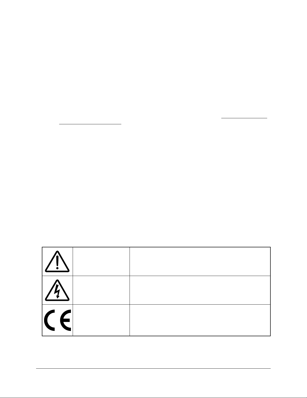
Symbols
Attention -
Consult Installation
and Operation Manual
Read, understand, and follow all instructions in this Installa-
tion and Operation Manual including all warnings, cautions,
and precautions before installing and using the product.
Caution –
Risk of Electrical
Shock
Potential Shock Hazard from Dangerous High Voltage.
CE Marking
Complies with the regulations of the European Union for
Product Safety and Electro-Magnetic Compatibility.
●Low Voltage Directive – EN 61010-1: 2001
●EMC Directive – EN 61327: 1997 + A1/1998 + A2/2001

Installation 9
Installation
Precautions
DANGER — HAZARDOUS VOLTAGES
WARNING - These installation/servicing instructions are for use by qualified personnel
only. To avoid electrical shock, do not perform any servicing other than that contained in
the operating instructions unless you are qualified to do so.
Always adhere to the following checklist:
1) Only qualified personnel or licensed electricians should install the WattNode meter. The
mains voltages of 120Vac to 600Vac can be lethal!
2) Install the meter in an electrical enclosure (panel or junction box) or in a limited access electri-
cal room.
3) Verify that circuit voltages and currents are within the proper range for the meter model.
4) Use only UL recognized current transformers (CTs) with built-in burden resistors, that gener-
ate 0.333Vac (333 millivolts AC) at rated current. Do not use current output (ratio) CTs
such as 1amp or 5 amp output CTs: they will destroy the WattNode meter and may
create a shock hazard. See Current Transformers (pg 60)for CT maximum input cur-
rent ratings.
5) Ensure that the line voltage inputs to the meter have either fuses or circuit breakers on each
voltage phase (not needed for the neutral wire). See Circuit Protection (pg 18)for details.
6) Equipment must be disconnected from the HAZARDOUS LIVE voltages before access.
7) The terminal block screws are not insulated. Do not contact metal tools to the screw termi-
nals if the circuit is live!
8) Do not place more than one line voltage wire in a screw terminal; use wire nuts instead. You
may use more than one CT wire per screw terminal.
9) Before applying power, ensure that all the wires are securely installed by tugging on each
wire.
10) Do not install the meter where it may be exposed to temperatures below -30°C or above
55°C, excessive moisture, dust, salt spray, or other contamination. The meter requires an
environment no worse than pollution degree 2 (normally only non-conductive pollution;
occasionally, a temporary conductivity caused by condensation must be expected).
11) Do not drill mounting holes using the meter as a guide; the drill chuck can damage the screw
terminals and metal shavings can fall into the connectors, causing an arc risk.
12) If the meter is installed incorrectly, the safety protections may be impaired.

10 Installation
Electrical Service Types
Below is a list of service types, with connections and recommended models. Note: the ground
connection improves measurement accuracy, but is not required for safety.
Model Type Line-to-
Neutral
Line-to-
Line
Electrical
Service Types
WNC-3Y-208-MB Wye 120 Vac 208–240
Vac
1 Phase 2 Wire 120V with neutral
1 Phase 3 Wire 120V/240V with neutral
3 Phase 4 Wire Wye 120V/208V with neutral
WNC-3Y-400-MB Wye 230 Vac 400 Vac 1 Phase 2 Wire 230V with neutral
3 Phase 4 Wire Wye 230V/400V with neutral
WNC-3Y-480 -MB Wye 277 Vac 480 Vac 3 Phase 4 Wire Wye 277V/480V with neutral
1 Phase 2 Wire 277V with neutral
WNC-3Y-600-MB Wye 347 Vac 600 Vac 3 Phase 4 Wire Wye 347V/600V with neutral
WNC-3D-240-MB Delta
or Wye
120 –140
Vac
208–240
Vac
1 Phase 2 Wire 208V (no neutral)
1 Phase 2 Wire 240V (no neutral)
1 Phase 3 Wire 120V/240V with neutral
3 Phase 3 Wire Delta 208V (no neutral)
3 Phase 4 Wire Wye 120V/208V with neutral
3 Phase 4 Wire Delta 120/208/240V with neutral
WNC-3D-400-MB Delta
or Wye 230 Vac 400 Vac 3 Phase 3 Wire Delta 400V (no neutral)
3 Phase 4 Wire Wye 230V/400V with neutral
WNC-3D-480-MB Delta
or Wye 277 Vac 480 Vac
3 Phase 3 Wire Delta 480V (no neutral)
3 Phase 4 Wire Wye 277V/480V with neutral
3 Phase 4 Wire Delta 240/415/480V with neutral
*The wire count does NOT include ground. It only includes neutral (if present) and phase wires.
Table 1 : WattNode Models
Single-Phase Two-Wire with Neutral
This configuration is most often seen in homes and offices. The two conductors are neutral and
line. For these models, the meter is powered from the Nand ØAterminals.
Figure 2: Single-Phase Two-Wire Connection
Ground
WHITE
BLACK
ØB CT
ØC CT
ØA CT
ØB
ØC
N
ØA
Common
B+, D1, RxD+/TxD+
EIA-485
PC or Logger
A−, D0, RxD−/TxD−
Continental Control Systems LLC
Status
Status
Status
X
C
B+
A-
MODBUS
Com
WNC-
WNC-
WATTNODE
®
MODBUS
-MB
-MB
Line
Neutral
LINE
LOAD
Shorting
Jumpers
Source
Face
Current
Transformer
3Y-xxx

Installation 11
Recommended WattNode Models
The following table shows the WattNode models that should be used, depending on the line to
neutral voltage.
Line to Neutral Voltage WattNode Model
120 Vac WNC-3Y-208-MB
230 Vac WNC-3Y-400-MB
277 Vac WNC-3Y-480-MB
Single-Phase Three-Wire (Mid-Point Neutral)
This configuration is seen in North American residential and commercial service with 240 Vac for
large appliances. The three conductors are a mid-point neutral and two line voltage wires with AC
waveforms 180° out of phase; this results in 120Vac between either line conductors (phase) and
neutral, and 240Vac (or sometimes 208Vac) between the two line conductors (phases).
Figure 3: Single-Phase Three-Wire Connection
Recommended WattNode Models
The following table shows the WattNode models that can be used. If neutral may or may not be
present, you should use the WNC-3D-240-MB (see Single-Phase Two-Wire without Neutral
below). If neutral is present, it must be connected for accurate measurements. If phase B may
not be present, you should use the WNC-3Y-208-MB (see Single-Phase Two-Wire with Neutral
above).
Meter Power Source WattNode Model
Nand ØA(Neutral and Phase A) WNC-3Y-208-MB
ØAand ØB(Phase A and Phase B) WNC-3D-240-MB
Ground
WHITE
BLACK
ØB CT
ØC CT
ØA CT
ØB
ØC
N
ØA
Common
B+, D1, RxD+/TxD+
EIA-485
PC or Logger
A−, D0, RxD−/TxD−
Continental Control Systems LLC
Status
Status
Status
X
C
B+
A-
MODBUS
Com
WNC-
WNC-
WATTNODE
®
MODBUS
-MB
-MB
Phase A
Neutral
Phase B
WHITE
BLACK
120 VAC
240 VAC
120 VAC
LINE
LOAD
Shorting
Jumper Source
Faces
Current
Transformers
3Y-208
3D-240

12 Installation
Single-Phase Two-Wire without Neutral
This is seen in residential and commercial service with 208 to 240 Vac for large appliances. The
two conductors have AC waveforms 120° or 180° out of phase. Neutral is not used. For this
configuration, the meter is powered from the ØAand ØB(phase A and phase B) terminals.
For best accuracy, we recommend connecting the N(neutral) terminal to the ground terminal.
This will not cause ground current to flow because the neutral terminal does not power the meter.
Figure 4: Single-Phase Two-Wire without Neutral Connection
Recommended WattNode Model
This configuration is normally measured with the following WattNode model.
Line-to-Line Voltage WattNode Model
208 - 240 Vac WNC-3D-240-MB
If neutral is available, you may also use the WNC-3Y-208-MB model. If you use the
WNC-3Y-208-MB, you will need to hook up the meter as shown in section Single-Phase Three-
Wire (Mid-Point Neutral) and connect neutral. You will need two CTs.
If one of the conductors (phase A or phase B) is grounded, see Grounded Leg Service below for
recommendations.
Ground
WHITE
BLACK
ØB CT
ØC CT
ØA CT
ØB
ØC
N
ØA
Common
B+, D1, RxD+/TxD+
EIA-485
PC or Logger
A−, D0, RxD−/TxD−
Continental Control Systems LLC
Status
Status
Status
X
C
B+
A-
MODBUS
Com
WNC-
WNC-
WATTNODE
®
MODBUS
-MB
-MB
Phase A
Phase B
WHITE
BLACK
208-240 VAC
LINE
LOAD
Shorting
Jumper Source
Faces
Current
Transformers
3D-240

Installation 13
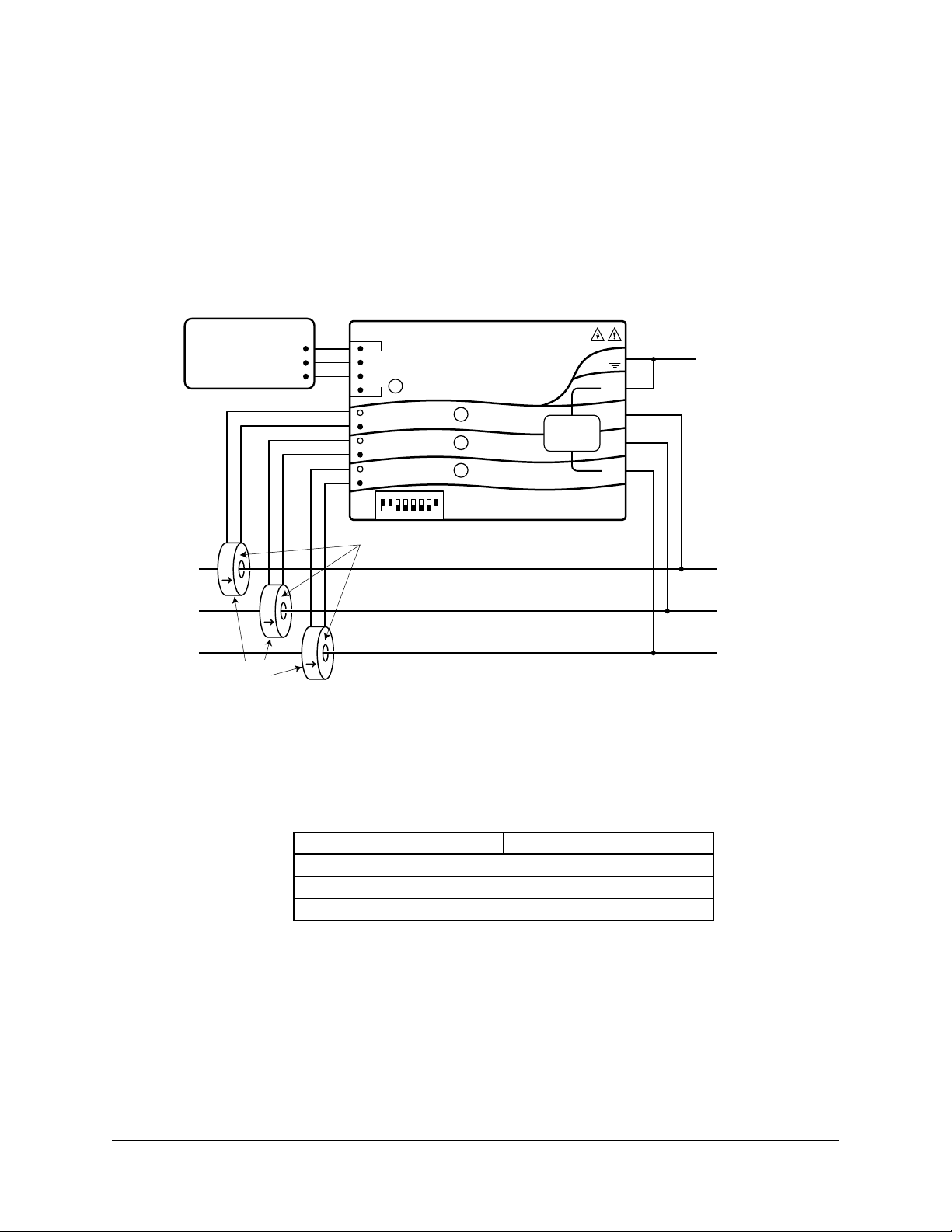
Three-Phase Four-Wire Wye
This is typically seen in commercial and industrial environments. The conductors are neutral and
three power lines with AC waveforms shifted 120° between phases. The line voltage conductors
may be connected to the ØA, ØB,and ØC terminals in any order, so long as the CTs are con-
nected to matching phases. It is important that you connect N(neutral) for accurate measure-
ments. For wye “-3Y” models, the meter is powered from the Nand ØAterminals.
Figure 5: Three-Phase Four-Wire Wye Connection
Recommended WattNode Models
The following table shows the WattNode models that should be used, depending on the line-to-
neutral voltage and line-to-line voltage (also called phase-to-phase voltage).
Line-to-Neutral Voltage Line-to-Line Voltage WattNode Model
120 Vac 208 Vac WNC-3Y-208-MB
230 Vac 400 Vac WNC-3Y-400-MB
277 Vac 480 Vac WNC-3Y-480 -MB
347 Vac 600 Vac WNC-3Y-600-MB
Note: you may also use the following delta WattNode models to measure three-phase four-wire
wye circuits. The only difference is that delta WattNode models are powered from ØAand ØB,
rather than Nand ØA. If neutral is present, it must be connected for accurate measurements.
Line-to-Neutral Voltage Line-to-Line Voltage WattNode Model
120 - 140 Vac 208 - 240 Vac WNC-3D-240-MB
230 Vac 400 Vac WNC-3D-400-MB
277 Vac 480 Vac WNC-3D-480-MB
Ground
WHITE
BLACK
ØB CT
ØC CT
ØA CT
ØB
ØC
N
ØA
Common
B+, D1, RxD+/TxD+
EIA-485
PC or Logger
A−, D0, RxD−/TxD−
Continental Control Systems LLC
Status
Status
Status
X
C
B+
A-
MODBUS
Com
WNC-
WNC-
WATTNODE
®
MODBUS
-MB
-MB
Neutral
Phase A
Phase B
Phase C
LOAD
WHITE
BLACK
WHITE
BLACK
LINE
Source
Faces
Current
Transformers
3Y-xxx
3D-xxx
14 Installation
Three-Phase Three-Wire Delta Without Neutral
This is typically seen in manufacturing and industrial environments. There is no neutral wire, just
three power lines with AC waveforms shifted 120° between the successive phases. With this
configuration, the line voltage wires may be connected to the ØA, ØB,and ØC terminals in any
order, so long as the CTs are connected to matching phases. For these models, the meter is
powered from the ØAand ØB(phase A and phase B) terminals. Note: all delta WattNode models
provide a neutral connection N, which allows delta WattNode models to measure both wye and
delta configurations.
For best accuracy, we recommend connecting the N(neutral) terminal to earth ground. This will
not cause ground current to flow because the neutral terminal is not used to power the meter.
Figure 6: Three-Phase Three-Wire Delta Connection
Recommended WattNode Models
The following table shows the WattNode models that should be used, depending on the line-to-
line voltage (also called phase-to-phase voltage).
Line-to-Line Voltage WattNode Model
208 - 240 Vac WNC-3D-240-MB
400 Vac WNC-3D-400-MB
480 Vac WNC-3D-480-MB
Three-Phase Four-Wire Delta (Wild Leg)
The uncommon four-wire delta electrical service is a three-phase delta service with a center-tap
on one of the transformer windings to create a neutral for single-phase loads.
See http://www.ccontrolsys.com/w/Four_Wire_Delta_Circuits for details.
Grounded Leg Service
In rare cases with delta services or single-phase two-wire services without neutral, one of the
phases may be grounded. You can check for this by using a multimeter (DMM) to measure the
Ground
WHITE
BLACK
ØB CT
ØC CT
ØA CT
ØB
ØC
N
ØA
Common
B+, D1, RxD+/TxD+
EIA-485
PC or Logger
A−, D0, RxD−/TxD−
Continental Control Systems LLC
Status
Status
Status
X
C
B+
A-
MODBUS
Com
WNC-
WNC-
WATTNODE
®
MODBUS
-MB
-MB
Phase A
Phase B
Phase C
WHITE
BLACK
WHITE
BLACK
LINE
LOAD
Source
Faces
Current
Transformers
3D-xxx
Installation 15
voltage between each phase and ground. If you see a reading between 0 and 5Vac, that leg is
probably grounded (sometimes called a “grounded delta”).
The WattNode meter will correctly measure services with a grounded leg, but the measured
voltage and power for the grounded phase will be zero and the status LED will not light for
whichever phase is grounded, because the voltage is near zero. Also, one or both of the active
(non-grounded) phases may show yellow or red/yellow LED flashing because the grounded leg
configuration can result in unusual measured power factors for delta services.
For optimum accuracy with a grounded leg, you should also connect the N(neutral) terminal
on the meter to the ground terminal; this will not cause any ground current to flow because the
neutral terminal is not used to power the meter. If you have a grounded leg configuration, you can
save money by removing the CT for the grounded phase, since all the power will be measured on
the non-grounded phases. We recommend putting the grounded leg on the ØBor ØCinputs and
attaching a note to the meter indicating this configuration for future reference.
Mounting
Protect the WattNode meter from moisture, direct sunlight, high temperatures, and conductive
pollution (salt spray, metal dust, etc.) If moisture or conductive pollution may be present, use an
IP 66 or NEMA 4 rated enclosure to protect the meter. Due to its exposed screw terminals, the
meter must be installed in an electrical service panel, an enclosure, or an electrical room. The
meter may be installed in any orientation, directly to a wall of an electrical panel or junction box.
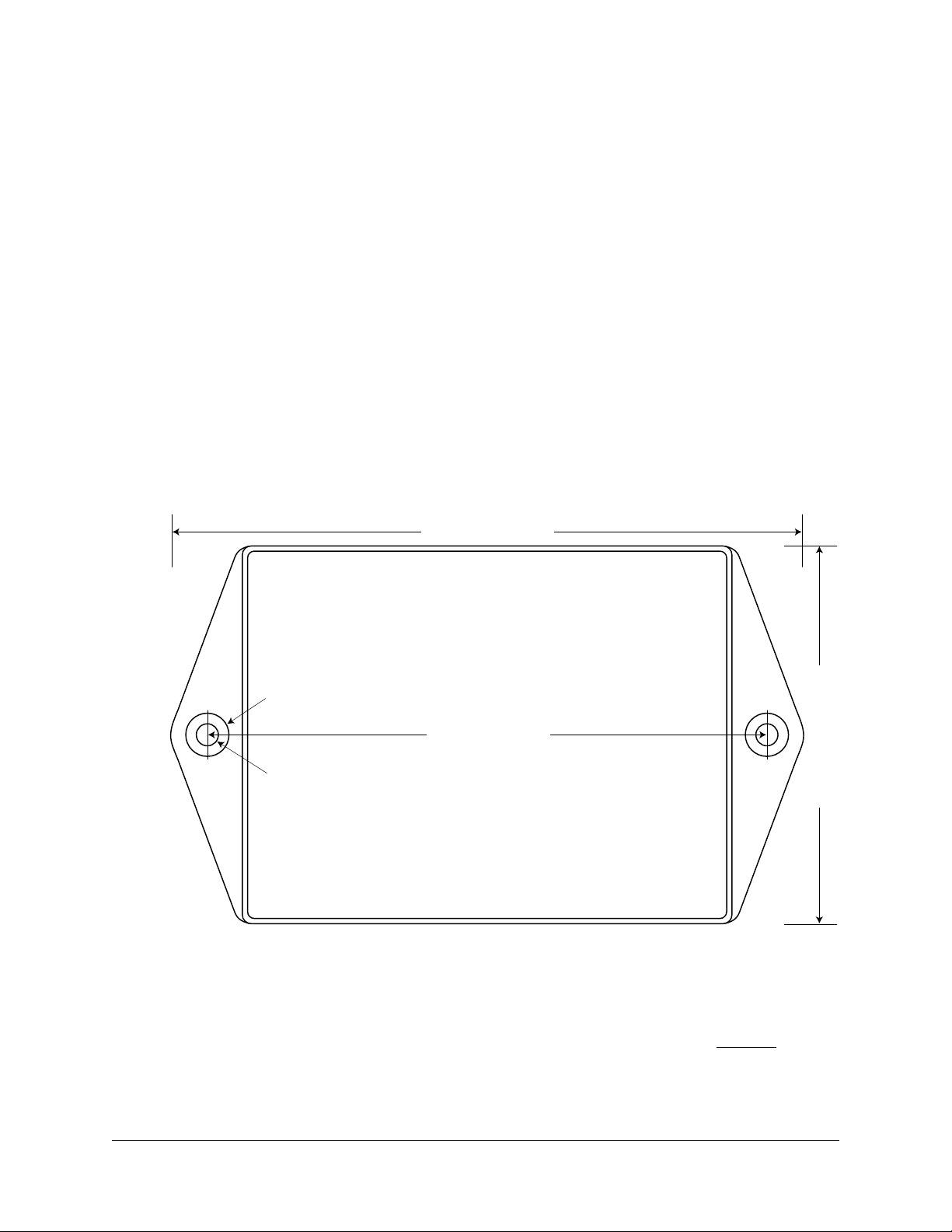
127 mm (5.0")
143 mm (5.63")
85.6 mm (3.37")
38 mm (1.50") High
Ø9.8mm (0.386")
Ø 5.1mm (0.200")
Drawn to Scale
Figure 7: WattNode Meter Dimensions
The WattNode meter has two mounting holes spaced 127 mm (5.0 in) apart (center to center).
These mounting holes are normally obscured by the detachable screw terminals. Remove the
screw terminals by pulling outward while rocking from end to end. The meter or Figure 7 may be
used as a template to mark mounting hole positions, but do not drill the holes with the meter in
the mounting position because the drill may damage the connectors and leave drill shavings in
the connectors.
You may mount the meter with the supplied #8 self-tapping sheet metal screws using 1/8” pilot

16 Installation
Selecting Current Transformers
The full-scale rated current of the CTs should normally be chosen somewhat above the maximum
current of the circuit being measured (see Current Crest Factor below for more details). In some
cases, you might select CTs with a lower rated current to optimize accuracy at lower current
readings. Take care that the maximum allowable current for the CT can not be exceeded without
tripping a circuit breaker or fuse; see Current Transformers (pg 60).
We only offer CTs that measure AC current, not DC current. Significant DC current can saturate
the CT magnetic core, reducing the AC accuracy. The most loads only have AC current, but
some rare loads draw DC current and may not be measured correctly. See our website for more
information: http://www.ccontrolsys.com/w/DC_Current_and_Half-Wave_Rectified_Loads.
CTs can measure lower currents than they were designed for by passing the wire through the
CT more than once. For example, to measure currents up to 1 amp with a 5 amp CT, loop the
wire through the CT five times. The CT is now effectively a 1 amp CT instead of a 5 amp CT. The
effective current rating of the CT is the labeled rating divided by the number of times that the wire
passes through the CT.
If you are using the measurement phases of the WattNode (ØA, ØB, and ØC) to measure dif-
ferent circuits, you can use CTs with different rated current on the different phases. Instead of
setting one CtAmps value for all phases, you can use different values for each phase: CtAmpsA,
CtAmpsB, and CtAmpsC.
Current Crest Factor
The term “current crest factor” is used to describe the ratio of the peak current to the RMS cur-
rent (the RMS current is the value reported by multimeters and the WattNode meter). Resistive
loads like heaters and incandescent lights have nearly sinusoidal current waveforms with a crest
factor near 1.4. Power factor corrected loads like computer power supplies typically have a crest
factor of 1.4 to 1.5. Many common loads can have current crest factors ranging from 2.0 to 3.0,
and higher values are possible.
The meter current transformer inputs will clip and become inaccurate if the peak current is too
high. This means you may want to be conservative in selecting the CT rated current. For example,
if your load draws 10 amps RMS, but has a crest factor of 3.0, then the peak current is 30 amps.
If you use a 15 amp CT, the meter will not be able to accurately measure the 30 amp peak cur-
rent. Note: this is a limitation of the meter measurement circuitry, not the CT.
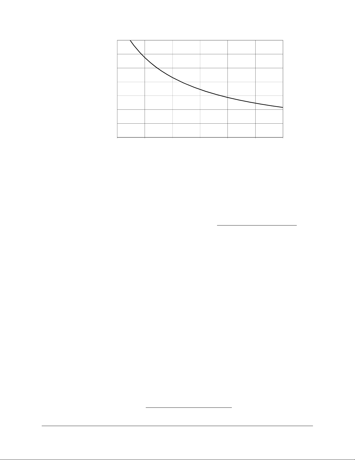
The following graph shows the maximum RMS current for accurate measurements as a function
of the current waveform crest factor. The current is shown as a percentage of CT rated current.
For example, if you have a 10 amp load with a crest factor of 2.0, the maximum CT current is
approximately 85%. 85% of 15 amps is 12.75, which is higher than 10 amps, so your measure-
ments should be accurate. On the other hand, if you have a 40 amp load with a crest factor of
4.0, the maximum CT current is 42%. 42% of a 100 amp CT is 42 amps, so you would need a
100 amp CT to accurately measure this 40 amp load.
hole (3.2 mm). Or you may use hook-and-loop fasteners. If you use screws, avoid over-tightening
which can crack the case. If you don’t use the supplied screws, the following sizes should work
(bold are preferred); use washers if the screws could pull through the mounting holes
Screw Style U.S.A. UTS Sizes Metric Sizes
Pan Head or Round Head #6, #8, #10 M3.5, M4, M5
Truss Head #6, #8 M3.5, M4
Hex Washer Head (integrated washer) #6, #8 M3.5, M4
Hex Head (add washer) #6, #8, #10 M3.5, M4, M5
Table 2: Mounting Screws
Installation 17
80%
100%
120%
140%
0%
20%
40%
60%
80%
1.0 1.5 2.0 2.5 3.0 3.5 4.0
Crest Factor
Maximum Accurate CT Current
(Percent of Rated Current)
Figure 8: Maximum CT Current vs. Crest Factor
You frequently won’t know the crest factor for your load. In this case, it’s generally safe to assume
the crest factor will fall in the 1.4 to 2.5 range and select CTs with a rated current roughly 150% of
the expected RMS current. So if you expect to be measuring currents up to 30 amps, select a 50
amp CT.
Connecting Current Transformers
●Use only UL recognized current transformers (CTs) with built-in burden resistors that generate
0.33333Vac (333.33 millivolts AC) at rated current. See Current Transformers (pg 60)for
the maximum input current ratings.
●Do not use ratio (current output) CTs such as 1 amp or 5 amp output CTs: they will destroy
the meter and present a shock hazard! These are commonly labelled with a ratio like 100:5.
●Find the arrow or label “THIS SIDE TOWARD SOURCE” on the CT and face toward the
current source: generally the utility meter or the circuit breaker for branch circuits. If CTs are
mounted backwards or with their white and black wires reversed the measured power will be
negative. The diagnostic LEDs indicates negative power with flashing red LEDs.
●Be careful to match up the current transformers to the voltage phases being measured. Make
sure the ØA CT is measuring the line voltage connected to ØA, and the same for phases B
and C. Use the supplied colored labels or tape to identify the wires.
●To prevent magnetic interference, the CTs on different phases should be separated by 1 inch
(25 mm). The line voltage conductors for each phase should be separated by at least 1 inch
(25 mm) from each other and from neutral.
●For best accuracy, the CT opening shouldn’t be much larger than the conductor. If the CT
opening is much larger, position the conductor in the center of the CT opening.
●Because CT signals are susceptible to interference, we recommend keeping the CT wires
short and cutting off any excess length. It is generally better to install the meter near the line
voltage conductors instead of extending the CT wires. However, you may extend the CT wires
by 300 feet (100 m) or more by using shielded twisted-pair cable and by running the CT wires
away from high current and line voltage conductors.
●OPTIONAL: if you see spurious readings on unused phases, jumper the unused CT inputs.
To connect CTs, pass the wire to be measured through the CT and connect the CT to the meter.
Always remove power before disconnecting any live wires. Put the line conductors through
the CTs as shown in the section Electrical Service Types (pg 10). You may measure gener-
ated power by treating the generator as the source.

18 Installation
Circuit Protection
The WattNode meter is considered “permanently connected equipment”, because it does not
use a conventional power cord that can be easily unplugged. Permanently connected equip-
ment must have overcurrent protection and be installed with a means to disconnect the
equipment.
●A switch, disconnect, or circuit breaker may be used to disconnect the meter and must be
as close as practical to the meter. If a switch or disconnect is used, then there must also be a
fuse or circuit breaker of appropriate rating protecting the meter.
●WattNode meters only draw 10-30 milliamps; CCS recommends using circuit breakers or
fuses rated for between 0.5 amps and 20 amps and rated for the line voltages and the cur-
rent interrupting rating required.
●The circuit breakers or fuses must protect the ungrounded supply conductors (the terminals
labeled ØA, ØB, and ØC). If neutral is also protected (this is rare), then the overcurrent protec-
tion device must interrupt neutral and the supply conductors simultaneously.
●Any switches or disconnects should have at least a 1 amp rating and must be rated for the
line voltages.
●The circuit protection / disconnect system must meet IEC 60947-1 and IEC 60947-3, as well
as all national and local electrical codes.
●The line voltage connections should be made with wire rated for use in a service panel or
junction box with a voltage rating sufficient for the highest voltage present. CCS recommends
14 or 12 AWG (1.5 mm2or 2.5 mm2) stranded wire, rated for 300V or 600V. Solid wire may be
used, but must be routed carefully to avoid putting excessive stress on the screw terminal.
●The WattNode meter has an earth connection, which should be connected for maximum
accuracy. However, this earth connection is not used for safety (protective) earthing.
For solid-core CTs, disconnect the line voltage conductor to install it through the CT opening.
Split-core and bus-bar CTs can be opened for installation around a wire by puling the removable
section straight away from the rest of the CT or unhooking the latch; it may require a strong pull.
Some CT models include thumb-screws to secure the opening. The removable section may only
fits one way, so match up the steel core pieces when closing the CT. If the CT seems to jam and
will not close, the steel core pieces are probably not aligned correctly; DO NOT FORCE together.
Instead, reposition or rock the removable portion until the CT closes without excessive force. A
nylon cable tie can be secured around the CT to prevent inadvertent opening.
Some split-core CT models have flat mating surfaces. When installing this type of CT, make sure
that mating surfaces are clean. Any debris between the mating surfaces will increase the gap,
decreasing accuracy.
Next, connect the CT lead wires to the meter terminals labeled ØA CT, ØB CT, and ØC CT. Route
the twisted black and white wires from the CT to the meter. We recommend trimming excess
length from the wires to reduce the risk of interference. Strip or trim the wires to expose 1/4” (6
mm) of bare wire. The current transformer leads connect to the six position black screw terminal
block. Connect each CT lead with the white wire aligned with the white dot on the label, and the
black wire aligned with the black dot. Note the order in which the phases are connected, as the
voltage phases must match the current phases for accurate power measurement.
Finally record the CT rated current as part of the installation record for each meter. If the wires
being measured are passed through the CTs more than once, then the recorded rated CT current
is divided by the number of times that the wire passes through the CT.

Installation 19
Connecting Voltage Terminals
Always disconnect power—by shutting off circuit breakers or removing fuses—before con-
necting the voltage lines to the meter. Connect each voltage input (green terminal block) to the
appropriate phase; also connect ground and neutral (if applicable).
So long as the phase voltages are the same, the meter voltage inputs do not need to be con-
nected to the same branch circuit as the load being monitored. In other words, if you have a
three-phase panel with a 100A three-phase breaker powering a motor that you wish to monitor,
you can power the meter (or several meters) from a separate low current (20 A) three-phase
breaker in the same panel.
When connecting the meter, do not place more than one voltage wire in a screw terminal; use
separate wire nuts or terminal blocks if needed. The screw terminals handle wire up to 12 AWG
(2.5 mm2). Prepare the voltage wires by stripping the wires to expose 1/4” (6 mm) of bare wire.
Connect each voltage line to the green terminal block as shown in the section Electrical Service
Types. Verify that the voltage line phases match the CT phases. After the voltage lines have
been connected, make sure the terminal blocks are securely installed on the meter.
If there is any doubt that the meter voltage rating is correct for the circuit being measured, then
before applying power, unplug the green screw terminal from the meter (so that you do not
damage the meter with excessive voltage), turn on the power, and use a voltmeter to compare the
voltages (probe the terminal block screws) to the values in the white box on the meter front label.
When power is first applied to the meter, check that the LEDs behave normally (see Installation
LED Diagnostics (pg 23)below): if you see the LEDs flashing red-green-red-green, then
disconnect the power immediately! This indicates the line voltage is too high for this model.
1.0sec
GRGRGRGRGRGR
GRGRGRGRGRGR
GRGRGRGRGRGR
C
B
A
Figure 9: WattNode LED Overvoltage Warning
The WattNode meter is powered from the voltage inputs: ØA(phase A) to N(neutral) for wye
“-3Y” models, or ØA to ØBfor delta “-3D” models. If the meter is not receiving at least 80% of the
nominal line voltage, it may stop operating. Since the meter consumes a small amount of power
itself (typically 1-3 watts), you may wish to power the meter from a separate circuit or place the
current transformers downstream of the meter, so its power consumption is not measured
For best accuracy, always connect the N(neutral) terminal on the meter. If you are using a delta
meter and the circuit has no neutral, then jumper the earth ground to the N(neutral) terminal.
Setting the Modbus Address
Every device on a Modbus network must have a unique address and the correct baud rate. The
WattNode Modbus meter sets the address and baud rate with an eight position DIP switch.
The WattNode meter supports Modbus addresses from 1 to 127 using the DIP switch. Address
0 is used for broadcast messages and is not a valid address. As shipped from the factory, the
meter will be configured with an address of 0, which is invalid and will prevent any communication
and cause the “Com” LED to light solid red.
Red
Set the Modbus address by switching DIP switch positions 1-7, each of which adds a different
value to the address. The change will take effect immediately.

20 Installation
DIP Switch 1 234567
Up (1) Value 1 2 4 8 16 32 64
Address Examples
1Up Down Down Down Down Down Down
1+2+4 = 7 Up Up Up Down Down Down Down
4+16 = 20 Down Down Up Down Up Down Down
1+2+16+32+64 = 115 Up Up Down Down Up Up Up
Table 3: Modbus Address Selection
For example, if DIP switch positions 3 and 5 are in the 1 (up) position and the rest are 0 (down),
the resulting Modbus address is 4 + 16 = 20.
Once you are communicating with the meter, you can change the address using either the DIP
switches or the Address (1652) register.
Setting all DIP switch positions to zero for ten seconds resets all communication settings to the
factory configuration. If you ordered communication options like Option EP, they will be applied.
This can be useful if you cannot communicate and need to return the meter to a known state.
Option AD
The WattNode Modbus meter can be ordered from the factory with the Modbus address pre-
programmed to any value from 1 to 247 using Option AD=xxx where xxx is the desired address.
If you want to change the address of a meter with Option AD, there are two options:
1) Set the address with the DIP switch: Set the DIP switches to the desired address, then
write 0 to the Address (1652) register (to override the factory programmed address). Finally,
write 1234 to the ApplyComConfig (1651) register to apply the new address.
2) Set the address with the Address register: Set the DIP switches to any non-zero address
so the meter won’t reset the address to the factory programmed value. Next write the new
address to the Address (1652) register. Finally, write 1234 to the ApplyComConfig (1651)
register to apply the change.
Baud Rate
Select the baud rate by setting DIP switch position 8 as shown below. The change will take effect
immediately. The baud rate can be programmed by the factory with Option 19K (19,200 baud)
or Option 38K (38,400 baud), in which case, DIP switch 8 has no effect. You may also use the
BaudRate register to reprogram the baud rate from 1,200 to 38,400 baud.
Baud Rate DIP Switch Position 8
9,600 (default) 0 (down)
19,200 1 (up)
Table 4: Baud Rate Selection
Connecting Modbus Outputs
The Modbus WattNode meter communicates using a serial EIA RS-485 interface. The meter uses
half-duplex two-wire (plus common) communication, so the same pair of wires is used for send-
ing AND receiving. Up to 127 devices can be connected together on the same RS-485 bus (or up
to 247 devices if you assign Modbus addresses using the Address register).
Planning the Modbus Network
EIA RS-485 networks should always be wired in a bus (or daisy-chain) configuration. In other
words, the bus should start at the PC, Modbus master, or monitoring device and then run to each
meter in turn. Try to avoid branches, and avoid home-run wiring (where each meter has its own
This manual suits for next models
6
Table of contents
Other WattNode Measuring Instrument manuals


