Watts Premier RO-PURE Plus User manual
Page 1
INSTALLATION, OPERATION AND MAINTENANCE MANUAL
Refer to enclosed warranty for operating parameters to ensure proper use with your water supply.
Save manual for future reference
Warning
Please read carefully before proceeding with installation. Your failure to follow any attached instructions
or operating parameters may lead to the product’s failure.
Model: RO-PURE Plus
System Tested and certied by WQA against NSF/ANSI Standard
58 for the reduction of the claims specied on the performance
data sheet, and NSF/ANSI 372 for “Lead Free” compliance.
Watts Premier 8716 W Ludlow Drive, Suite 1 Peoria, AZ 85381
Phone: 800-752-5582 www.premierH2o.com Fax: 623-866-5666
Manual: 199519 Manual Date: 07/20/2016

Page 2
Thank you for your purchase of a state of the art Premier Reverse Osmosis (RO) water treatment system. Water
quality concerns are becoming more of a focus for the public. You may have heard about contaminants in the drinking
water such as Arsenic, Chromium, Cryptosporidium or Giardia. There may also be some local water issues such as
high levels of Lead and Copper. This Premier water treatment system has been designed and tested to provide you
with high quality drinking water for years to come. The following is a brief overview of the system.
Your Reverse Osmosis System:
Osmosis is the process of water passing through a semi permeable membrane in order to balance the concentration
of contaminants on each side of the membrane. A semi permeable membrane is a barrier that will pass only certain
particles like clean drinking water, but not other particles like arsenic and lead.
Reverse osmosis uses a semi permeable membrane; however, by applying pressure across the membrane, it
concentrates contaminants (like a strainer) on one side of the membrane, producing crystal clear water on the other.
This is why RO systems produce both clean drinking water and rinse water that is ushed from the system. This reverse
osmosis system also utilizes carbon block ltration technology, and can therefore provide a higher quality drinking
water than carbon ltration systems alone.
Your system is a four stage RO which is based upon separate treatment segments within the one complete water
ltration system. These stages are as follows:
Stage 1 – Sediment lter, recommended change 6 months.
The rst stage of your RO system is a ve micron sediment lter that traps sediment and other particulate
matter like dirt, silt and rust which affect the taste and appearance of your water.
Stage 2 – Carbon lter, recommended change 6 months.
The second stage contains a 5 micron carbon block lter. This helps ensure that chlorine and other materials
that cause bad taste and odor are greatly reduced.
Stage 3- Membrane, recommended change 2-5 years.
Stage three is the heart of the reverse osmosis system, the 50GPD (Gallons Per Day) RO membrane. This
semi permeable membrane will effectively remove TDS, Sodium and a wide range of contaminants such
as Chromium, Arsenic, Copper, Lead as well as Cysts, such as Giardia and Cryptosporidium. Because the
process of extracting this high quality drinking water takes time, your RO water treatment system is equipped
with a storage tank.
Stage 4- VOC Block lter, recommend change 12 months.
Premier RO-Pure Plus system conforms to NSF/ANSI 58 for VOC reduction. Through the specialty (VOC)
like MTBE’s, Atrazine, Benzene, 2,4-D,Lindane and others from your drinking water. It is estimated that
VOC’s are present in one-fth of the nation’s water supplies. These water contaminants can enter ground
water from a variety of sources including localized use of herbicides and pesticides, gasoline or oil spills,
leaking underground fuel tanks, septic system cleaners, and chemicals used in the dry-cleaning industry.
See performance data sheet for individual contaminants and reduction performance.
Note: Filter & Membrane life may vary based upon local water conditions and/or use patterns.
System Maintenance
Just because you cannot taste it, does not mean that it is not there. Contaminants such as Lead, Chromium and Arsenic
are undetectable to the taste. Additionally, over time if you do not replace the lter elements, other bad tastes and
odors will be apparent in your drinking water.
It is important to change out your lters at the recommended intervals as indicated in this system manual. When
replacing the lter elements, pay special attention to any cleaning instructions. Should you have any further questions
please refer to our web site at www.premierH2o.com or call our customer service department at 1-800-752-5582.

Page 3
** Before installation, please take a moment to ll out the warranty card on page 23.
Table of Contents
Operational Parameters................................................................................................................... 4
Contents of Reverse Osmosis System............................................................................................ 4
Installation & Startup
Tools Recommended For Installation .............................................................................................. 4
Plumbing diagram and parts list...................................................................................................... 5
Drill a Hole for the Reverse Osmosis Faucet .................................................................................. 6
How to use Quick Connect Fittings on Your RO System ................................................................ 6
Faucet Installation .......................................................................................................................... 7
Adapt-a-Valve Installation ............................................................................................................... 8
Drain Saddle Installation.................................................................................................................. 9
Drain Saddle Tube Connection........................................................................................................ 9
Blue Tube Connection ................................................................................................................... 10
Red Tube Connection.................................................................................................................... 10
Green Tube Connection .................................................................................................................11
Reverse Osmosis Module Mounting...............................................................................................11
Tank Ball Valve Installation .............................................................................................................11
Blue Tube Connection (From The Storage Tank to Shut Off Valve) ...............................................11
Start up Instructions....................................................................................................................... 12
Maintenance & Troubleshooting
Changing The Filter Cartridges ..................................................................................................... 13
Membrane Replacement .............................................................................................................. 13
Annual Sanitization ....................................................................................................................... 14
Check Air Pressure in the Tank ..................................................................................................... 15
Procedure for Extended Non-Use (More than 2 months).............................................................. 15
Troubleshooting ............................................................................................................................ 16
Product Technical & Warranty Information
Performance Data Sheet................................................................................................................ 17
VOC Performance Data Sheet ....................................................................................................... 18
Arsenic Fact Sheet ......................................................................................................................... 19
Service Record............................................................................................................................... 21
Limited Warranty ............................................................................................................................ 22

Page 4
Installation must comply with State and local plumbing regulations. Do not use with water that is micro
biologically unsafe or of unknown quality without adequate disinfection before or after the system.
System is intended to be installed using the cold water supply only.
Tools Recommended For Installation
√ 1 1/4" Diamond Tipped Hole Saw bit for faucet opening (Counter Tops/Porcelain & Stainless Sinks)
√ 1 1/4” Adjustable Wrench √ Phillips bit for electric drill
√ 1/2" Open End Wrench √ Needle Nose Pliers
√ 5/8” Open End Wrench √ Adjustable Pliers
√ Electric Drill √ Sharp Knife
√ 1/8" diamond tip bit, pilot hole √ Phillips Screw Driver
√ 1/4” drain saddle hole
Contents of the Reverse Osmosis (RO) System
Operating Temperatures: Maximum 100°F (37.8°C) Minimum 40°F (4.4°C)
Operating Pressure: Maximum 100 psi (7.0 kg/cm
2
)Minimum 40 psi (2.80 kg/cm
2
)
pH Parameters: Maximum 11 Minimum 2
Iron: Maximum 0.2 ppm
TDS (Total Dissolved Solids) < 1800 ppm
Turbidity < 5 NTU
Hardness Maximum 10 Grains Per Gallon *
Hardness: Recommended hardness not to exceed 10 grains per gallon, or 170 parts per million.
* System will operate with hardness over 10 grains but the membrane life may be shortened.
Addition of a water softener may lengthen the membrane life.
Copper Tube: Reverse Osmosis water should not be run through copper tube as the purity of the
water will leach copper causing an undesired taste in water and pin holes may form in the tube.
Water Pressure: The operating water pressure in your home should be tested over a 24 hour
period to attain the maximum pressure. If the incoming water pressure is above 100 psi then a
water pressure regulator is required. A booster pump is needed for incoming water pressure
under 40psi.
Operational Parameters
INSTALLATION & STARTUP
1 Tank
1 Module – (Filters Pre-Installed)
1 Parts Bag
1 Faucet Box
1 Manual
If any of the items are missing please contact Premier prior to installing.
Page 5
Part No. Description
1 115304 FILTER MODULE
2 134003 AUTOMATIC SHUT OFF VALVE
3 119007 STORAGE TANK - 3 GALLONS
4 560080 ADAPT-A-VALVE KIT
5 420102 FAUCET - TMT - BRUSHED NICKEL
6 134018 TANK VALVE - 1/4F X 1/4” QC
7 164056 DRAIN SADDLE - 3/8” QC - KIT
8 119028 TANK STAND
9 142000 1/4” GREEN TUBING WITH 90° BEND - 4FT
10 142001 1/4” BLUE TUBING WITH 90° BEND - 4FT
11 400048 3/8” BLACK TUBING - 3FT X 1
12 142002 1/4” RED TUBING WITH 90° BEND - 4FT
13 105311 SEDIMENT PRE-FILTER (RED)
14 105351 CARBON PRE-FILTER (YELLOW)
15 105331 REVERSE OSMOSIS MEMBRANE 50GPD (GREEN)
16 105381 VOC CARBON POST FILTER (SILVER)
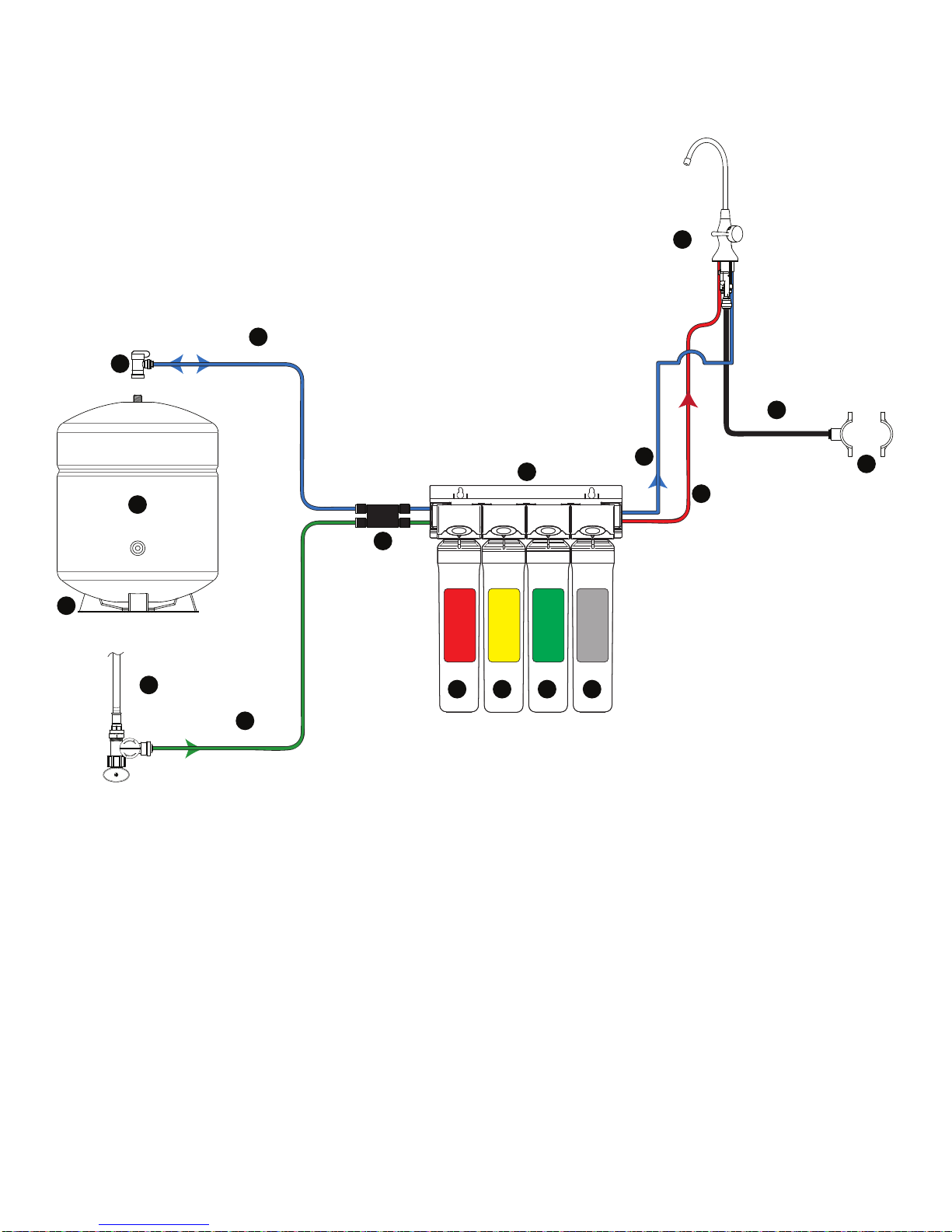
Plumbing Diagram and Parts List
COLD WATER
ANGLE-STOP
(SUPPLY)
TANK
FAUCET
GREEN- 1/4” TUBE
FEED
1
5
3
RED - 1/4” TUBE
BRINE
6
BLUE - 1/4” TUBE
FAUCET
BLUE - 1/4” TUBE
TANK
DRAIN
SADDLE
7
2
AUTO SHUT-OFF VALVE
8
9
BLACK - 3/8” TUBE
DRAIN
10
11
12
10
ADAPT
-A-
VALVE
413 14 15 16

Page 6
After drilling, remove all sharp edges and make sure the surroundings
of the sink are cooled before mounting the faucet.
Step 3
Step 4
Determine desired location for the RO faucet on your sink and place
a piece of masking tape over where the hole is to be drilled. Mark the
center of the hole on the tape.
Step 1
Using a variable speed drill set on the slowest speed, drill a 1/8“ pilot
hole through both porcelain and metal casing of sink at the marked
center of the desired location. Use lubricating oil or liquid soap to keep
the drill bit cool (If drill bit gets hot it may cause the porcelain to crack
or chip).
Using a 1 ¼” diamond tip hole saw, proceed to drill the large hole. Keep
drill speed on the slowest speed and use lubricating oil or liquid soap
to keep the hole saw cool during cutting.
Step 2
Counter Top / Porcelain & Stainless Steel Sink
Note: Most sinks are pre drilled with 1 ¼” diameter hole that you can use for your RO faucet.
(If you are already using it for a sprayer or soap dispenser, see step 1)
Porcelain sinks are extremely hard and can crack or chip easily.
Use extreme caution when drilling. Watts accepts no responsibility for
damage resulting from the installation of faucet. Diamond tip bit recommended.
Marble Counter-top
We recommend contacting a qualied contractor for drilling a hole in a marble counter-top.
Drill a Hole for the Reverse Osmosis Faucet
How to use the Quick Connect Fittings
To make a connection, the tube is simply pushed into the tting. The unique locking system holds the tube rmly in place
without deforming it or restricting ow. Use the steps below in reference to any quick connect tube connections.
It is essential that the outside diameter be free of score
marksand that burrs and sharp edges beremoved before
inserting into tting.
Fitting grips before it seals. Ensure tube is pushed into
the tube stop.
Push the tube into the tting, to the tube stop. The collet
(gripper) has stainless steel teeth which hold the tube
rmly in position while the O-ring provides a permanent
leak proof seal.
Pull on the tube to check that it is secure. It is a good practice
to test the system prior to leaving site and /or before use.
To disconnect, ensure the system is
depressurized before removing the tube. Push in the col-
lect squarely against face of tting. With the collet held
in this position, the tube can be removed. The tting can
then be reused.

Page 7
Connect tubes to the RO faucet (Figure A)
This RO faucet is equipped with quick connect ttings for easy tube
installation.
1. In the parts bag, locate one 1/4” red tube, one 1/4” blue tube and one
3/8” black tube.
2. Connect the STRAIGHT END of the 1/4”-BLUE tube to the corresponding
tting at the base of the faucet. Make sure the tube is inserted the full
3/4” into the tting.
3. Connect the STRAIGHT END of the 1/4”-RED tube to the corresponding
tting at the base of the faucet. Make sure the tube is inserted the full
3/4” into the tting.
4. Connect the 3/8” BLACK tube to the tting at the base of the faucet with the
black ring. Make sure the tube is inserted the full 3/4” into the tting.
Mount the RO faucet (Figure B)
NOTE: A 1.25” mounting hole is required for faucet installation.
5. Make sure the Locking Tabs are “tucked”. Feed the tubes and the lower
faucet assembly through the mounting hole in the sink. Test t faucet
placement.
6. Makesurethelowerfaucetassembly is seated properly insideoftherubber
washer groove
NOTE: Arrow on base indicates FRONT of faucet.
6. Using a Phillips screwdriver, tighten the two screws until snug. Then, tighten
each screw alternately until faucet is secure. Do not overtighten!
7. Inspect O-rings on lower faucet assembly. Lubricate with water-soluble
lubricant if needed.
Assemble Faucet (Figure C)
7. Align the release button on the back of the upper faucet assembly
approximately 45° left off the back of the lower faucet assembly.
8. Press the upper faucet assembly rmly on-to the lower faucet assembly
and twist clockwise until locked into place. Remove battery cover on faucet
handle, pull battery tab and replace battery cover.
To Remove Upper Assembly:
Press in the release button and twist upper faucet assembly counter-
clockwise.
Do not remove upper faucet assembly until all water has been
drainedfromthesystemandsystemhas beenfullydepressurized.
L.E.D. FAUCET MONITOR INDICATOR
This faucet is equipped with a lter change indicator. The indicator light will
ash BLUE while the water is being dispensed. After approximately six months
or 2000 gallons of ltered water used the light will change to RED, indicating
that lters should be changed. After lter change you must reset the monitor
(Follow the Faucet Indicator Battery Replacement procedure on page 8).
DANGER This product contains a button cell battery. If swallowed,
it could cause severe injury or death in just 2 hours. Seek
medical attention immediately.
Premier Monitored (Top Mount Twist) Faucet Installation
INSERT
3/8”-BLACK TUBE
INSERT
1/4”-RED TUBE
INSERT
1/4”-BLUE TUBE
RUBBER
WASHER
FRONT
RELEASE
BUTTON
BATTERY
TAB
TWIST
UPPER
ASSEMBLY
45° ONTO
BASE
LOCKING
TABS
BACK
Figure A
Figure B
Figure C
LOWER
FAUCET
ASSEMBLY
UPPER
FAUCET
ASSEMBLY
LUBRICATE
O-RINGS
FRONT
Page 8
Turn off the cold water supply to the faucet by turning the angle stop valve completely off.
Open cold water sink faucet to relieve pressure.
Step 5
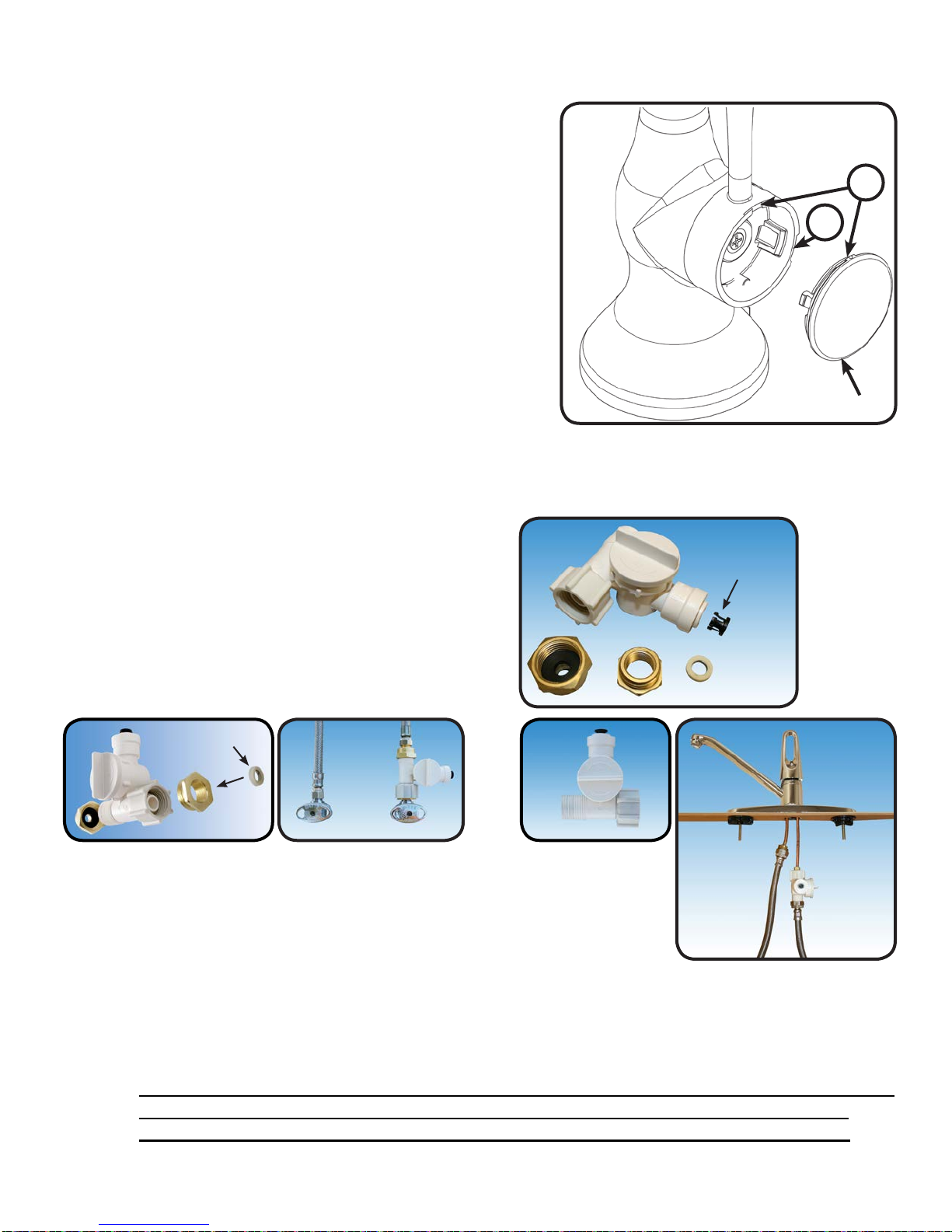
Step 6 Choosing the conguration that ts your plumbing, attach the adapt-a-valve as illustrated in
the four photos above.
Adapt-a-Valve Installation
Do not use Teon tape with the Adapt-a-Valve.WARNING:
Caution:
Water supply line to the system must be from the cold water supply line only.
Hot water will severely damage your system.
3/8” Conguration
(With Brass Fittings)
* Insert White Washer
1/2” Conguration
(Without Brass
Fittings)
*White
Washer
Hot
Supply Cold
Supply
Hot
Supply Cold
Supply
Verify contents prior to installation:
( 1 ) - Plastic Adapt-a-Valve with black collet
( 1 ) - Brass Adapter no washer
( 1 ) - Brass Adapter with black washer
( 1 ) - White rubber washer
Make sure that the black collet is installed in to the 1/4” opening on the Adapt-a-valve.
Don’t forget to install the white compression washer with the 3/8” conguration.
Brass adapter (A) does not need to be tightened with a wrench, only nger tight.
Black
Collet
A
TIPS:
A
White
Washer
1. Turn the handle on the storage tank ball valve to the
“off” position and lower faucet handle to “on” position.
2. Remove the faucet handle cover at the slot - (A).
Note: Water will dribble out of the spout, use caution
when handling the electronic components.
3. Slide the old battery out and replace with new battery.
Note: Once the battery is pushed into the clip a red and
blue light will ash indicating proper installation.
4. Replace cover assembly onto the faucet handle while
aligning the tab on the cover with the notch on
the faucets handle - (B).
B
A
COVER
Faucet Indicator Battery Replacement

Page 9
Drain Saddle ts standard 1 ¼” – 1 ½” drain pipes
Drain Saddle Installation
Step 7
Step 8
Step 9 The drain saddle must be installed at least 1 ½” above the nut
of the P-Trap elbow or cross bar from the garbage disposal to
insure proper drainage. Using the 1/4” drill bit, drill into the drain
pipe at best available location as specied above, for drain saddle
installation. Take extreme caution to only drill through one side
of the drain pipe.
The small square black foam gasket with a circle cut out of the middle
must be applied to the inside of the drain saddle. Remove sticky tape
backing and stick to the drain saddle as shown.
1 Semicircle bracket with opening
2 Screws 1 Foam gasket
2 Nuts for screws 1 Semicircle bracket
Gather the pieces of the drain saddle:
Caution: Do not over tighten the screws. It may crack the drain saddle.
If you have a garbage disposal, do not install the drain saddle near it.
Installation of the drain saddle must be either above the garbage disposal, or
if a second sink drain is available, install it above the cross bar on the second
drain. Installation of the drain saddle near a garbage disposal may cause
the drain line to plug. If no other installation of drain line is available, Premier
offers drain line installation kit (part number 164020) that can be used with
garbage disposals.
Caution:
The black 3/8” drain tube must be as SHORT and STRAIGHT as possible to the drain
saddle, making a downward slope from faucet to drain saddle to allow for proper
drainage. This is a gravity fed line and if there is any bend or dip in the tube, the rinse
water will not ow into the drain properly. Water may back up and come out the air
gap hole in the back of the faucet.
IMPORTANT:
Measure the 3/8” black tube from faucet to the drain saddle on the
drain pipe and make a straight cut to the correct length.
Connect the black tube to the open quick connect tting on the drain
saddle by pushing the tube all the way to the tube stop.
Step 12
Step 11
Assemble the drain saddle around the drain pipe and align drain
saddle tting opening with the hole drilled in the previous
step - you may use a small screwdriver to feed through the drain
saddle into the drain pipe to aid with the alignment. Using a Phillips
screw driver tighten the drain saddle bolts evenly and securely on
both sides.
Step 10
Page 10
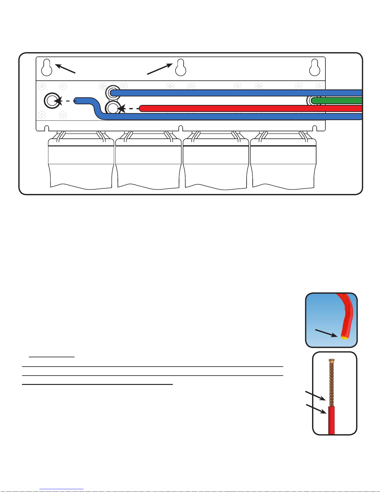
Red Tube Connection (From FAUCET To The RO Module)
Locate the 1/4” RED tube attached to the RO faucet. Insert the end of the
red tube with the 90* bend into the open 1/4” quick connect tting on the
back side of the RO-Pure Head behind the Membrane head making sure
the tube is pushed in all the way to the tube stop. See Diagram Above
Step 14
* IMPORTANT:
The Flow Restrictor is installed inside of the red tube at the bent end. DO
NOT REMOVE THE FLOW RESTRICTOR OR CUT THE RED TUBING AS IT
WILL DAMAGE THE FLOW RESTRICTOR.
Blue Tube Connection (From FAUCET To The RO Module)
Locate the 1/4” BLUE tube from the RO faucet. Insert the open end of the tube with the 90*
bend into the open 1/4” quick connect tting on the back side of the RO-Pure Head behind
the Post Filter head making sure the tube is pushed in all the way to the tube stop. See
Diagram Above
Step 13
Rear View of RO-Pure System
RED TUBE - BRINE
BLUE TUBE - FAUCET
BLUE TUBE - TANK
GREEN TUBE
SEDIMENT
PRE CARBONMEMBRANEVOC CARBON
Mounting Holes
Flow
Restrictor
Insert
Flow Restrictor
Red Tubing to Manifold
(Attached to faucet)
Page 11
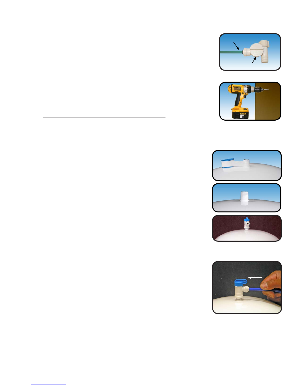
Blue Tube Connection (From The Tank to Shut off Valve)
Position tank in desired location. Stand it upright or lay it on
its side (using the black plastic stand). Measure the blue tube
(marked “TANK”) from the RO module to the tank and cut it to
length leaving a straight, square edge. Insert the tube into the
quick connect tting on the tank ball valve. Make sure the tube
is pushed in all the way to the tube stop (see page 7 for quick
connect tting use directions).
Step 19
Teon tape must be applied in a clockwise direction. Wrap
(7 to 12 turns) around the male pipe threads (MPT) on the
stainless steel tting on top of the tank.
Tank Ball Valve Installation
Thread the quick connect ball valve (supplied in the parts bag)
onto the stainless steel connector on the tank.
Note: Do not over-tighten plastic connections.
Step 17
Step 18
Note: Set the blue ball valve knob in-line with the blue tube, this is the “open” position.
Reverse Osmosis Module Mounting
Step 16 Determine best location for the RO module to be mounted to allow
for future system maintenance. The parts bag has 2 self tapping
screws. Using an electric drill with a Phillips bit, screw them into
the cabinet wall 6” apart and 16” from the bottom of the cabinet.
Do not cut any RO system tubes at this timeNote:
Green Tube Connection
Step 15 Locate green tube attached to the RO Module. Insert the open
end of the green 1/4” tube into the open 1/4” quick connect tting
on the plastic water feed valve making sure the tube is pushed in
all the way to the tube stop.
Green Tube
Adapt-a-Valve

Page 12
Startup Instructions
If you have connected your RO system to a refrigerator / ice maker, make sure the ice maker is
off (do not allow water to ow to the ice maker) until ushing (Step 4) is complete and the tank
has been allowed to ll completely. Connection from the RO to the ice maker system should
have an in-line valve installed before the ice maker so it can easily be closed to prevent water
owing to the ice maker during start up and periodic maintenance. Your storage tank must be
allowed to ll up fully in order for the ice maker system to work properly.
After the storage tank has lled open the RO Faucet to ush the tank completely. You will
know that the tank is empty when the ow rate from the RO faucet is down to a trickle. Repeat
this step two more times. The fourth tank can be used for drinking.
Open the RO faucet and leave it open until water begins to trickle out (this may take a few
minutes and the water will come out slowly).
Step 4
Turn on the incoming cold water at the angle stop valve and the
Adapt-a-Valve. Check the system for leaks and tighten any ttings
as necessary. (Check frequently over the next 24 hours to ensure
no leaks are present).
Step 3
Step 2
Note:
Step 1
Close the RO faucet allowing the storage tank to ll with water. It may take 3 to 6 hours to
ll the tank completely depending on the production capability of the membrane, local water
temperature and water pressure.
Flushing of the tank 3 times is only necessary during the initial startup and after replacing the
membrane.
During the ll period you may hear water trickling which is a normal occurrence.
Note:
Note:
Congratulations!
You have completed the installation of your new Reverse Osmosis system.
Please Follow the Startup Instructions.
The ushing process should take about a day to complete.
ON

Page 13
Place a towel under the RO module to catch any excess water that
may drip out from the lters during the changeover.
Step 1
Your RO module is equipped with valve heads which will automatically turn off the water supply to each
lter when the lter is released, thus you do not need to turn off the incoming water supply at the Adapt-
a-Valve. The RO faucet must be off when lters are replaced. To make the removal of the lter cartridges
easier, the heads & cartridges may be swiveled up to 90 degrees as shown in the pictures below.
Step 2
To install a lter cartridge: Remove the seal cap and insert
the cartridge into the valve head until you hear an audible “click”
(the button does not need to be pressed to install new lters).
Step 3
To remove a lter cartridge: Push & hold the button on the
valve head above the lter. Pull cartridge downward (from the
head) to remove. Release button and discard old lter.
Changing The Filter Cartridges
Membrane Replacement (2 - 5 Years)
√ One Membrane (50 GPD Green Label P/N: 105331)Replace:
Membranes have a life expectancy between 2 and 5 years, depending on the incoming water conditions and the
amount the RO system is used. This reverse osmosis membrane is critical for effective reduction of total dissolved solids
(TDS). The product water should be tested periodically to verify that the system is performing satisfactorily.
Normally, a membrane would be replaced during a semiannual or annual lter change. However, if at any time you
notice a reduction in water production or an unpleasant taste in the reverse osmosis water, it could be time to replace the
membrane. Premier recommends replacing the membrane when TDS reduction falls below 75%.
A water sample may be sent to Premier for a free diagnosis of your membranes performance. To send a water
sample, use 2 clean containers and ll 1/2 cup of tap water in one container and 1/2 cup of RO water in 2nd container. Clearly
label each sample. Send the samples to the address listed on the cover of this manual attention “Water Samples”. Premier
will test the water and mail or call you with the results.
You must reset the faucet monitor. Follow procedure on page 8.
Note:
This reverse osmosis system contains a replaceable component (the RO membrane) which is critical to the
efciency of the system. Replacement of this reverse osmosis membrane should be with one of identical
specications as dened by Premier to assure the same efciency and contaminant reduction performance.
Annual Maintenance-(Sanitization Recommended See PG.15)
√ One sediment lter (Red Label P/N: 105311)
√ One carbon pre-lter (Yellow Label P/N: 105351)
√ One carbon VOC-lter (Silver Label P/N: 105381)
Replace:
√ One sediment lter (Red Label P/N: 105311)
√ One carbon pre-lter (Yellow Label P/N: 105351)
Replace:
6 Month System Maintenance
Tip: This is a good time to check the air pressure in your storage
tank. For instructions please see page 14.
Flush rst tank full after completing the annual maintenance.
Note:
PULL
PRESS
Page 14
Annual Sanitization
NOTICE Do not change your post-carbon lter until the sanitization has been completed.
The pre-lters and membrane can be changed before the sanitization
Step 1: Turn off the water supply to your RO system at the adapt-a-
valve and open the RO faucet to drain the storage tank.
NOTICE If you have connected your RO system to a refrigerator/
ice maker, make sure the connection has been turned
off. Do not re-open the connection until the sanitization
process is complete.
Step 2: Locate the tube that runs between your lter module and the
storage tank and disconnect at both ends.
Step 3: Drain any remaining water in the tube
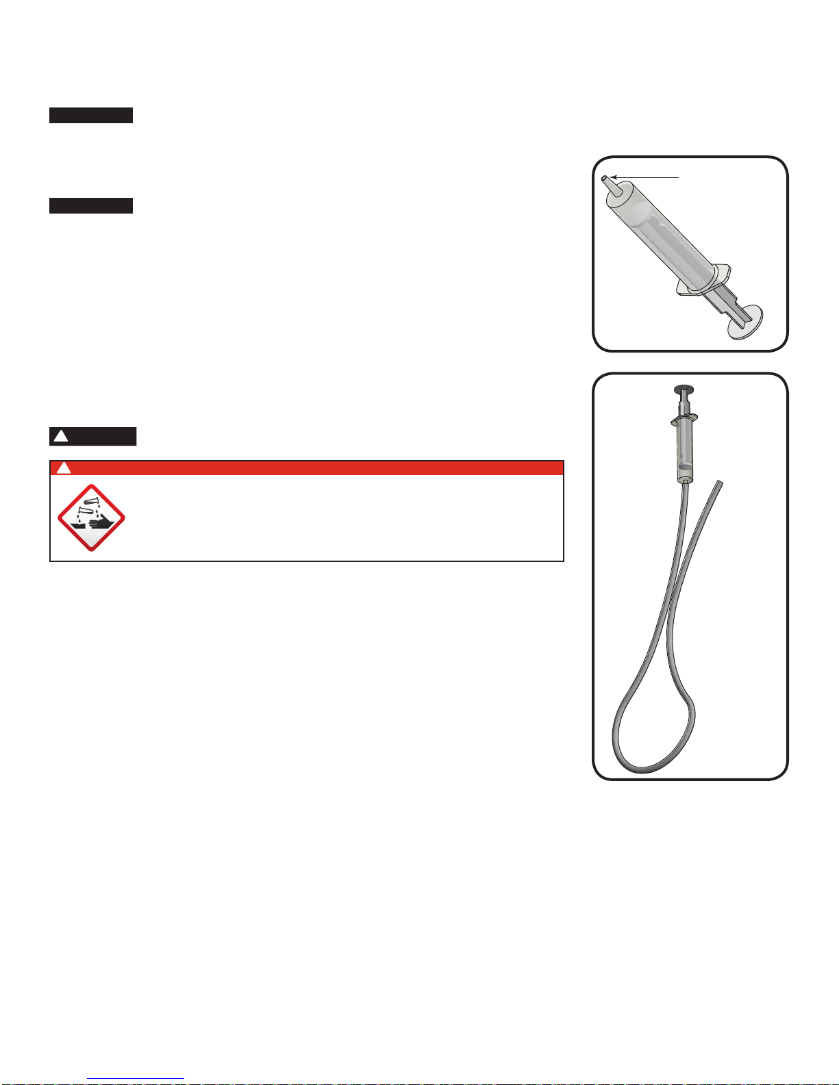
Step 4: Hold both ends of the tube together with the ends pointed
away from your face. Using a dosing syringe (see gure)
slowly insert 1 teaspoon (5 mL) of common household bleach
into the tube.
WARNING
!Do not use needle syringe
DANGER
!
IF BLEACH GETS IN EYES: Hold eye open and rinse
slowly and gently with water for 15 - 20 minutes.
Remove contact lenses if present, after the first 5
minutes, then continue rinsing eye. Call a poison
control center or doctor for treatment advice.
Step 5: While covering one end of the tube with your nger, insert the
other into the tank. Then insert the open end into the lter
module.
Step 6: Turn the incoming water back on and let the system ll for
approximately 10 minutes
Step 7: Turn off the incoming water and let the system sit for 1 minute.
Step 8: Drain the system completely and then follow the startup
procedure - lling then draining two full tanks of water.
Step 9: Replace the post-carbon lter once complete.
POINT HOSE
ENDS AWAY
FROM FACE
DOSING SYRINGE
WITH NO NEEDLE

Page 15
Check Air Pressure in the Tank
NOTICE Check air pressure only when tank is empty of water!
Check air pressure in the storage tank when you notice a decrease in available water from the RO sys-
tem. Air can be added with a bicycle pump using the schrader valve that is located on the lower side of
the tank behind the blue plastic cap.
Step 1: Turn off the incoming water supply to the RO.
Step 2: Open the RO Faucet and allow water to drain from the tank
until it is completely empty.
TIP: When water from the RO faucet slows to a trickle, with the
faucet still in the open position, you may add air to the
tank to purge any left over water, this will ensure that the
tank is completely empty.
Step 3: Once all water in the tank is purged, check air pressure using an air pressure gauge, it
should read between 5 - 7 PSI. (Digital air pressure gauge is recommended)
Step 4: Follow startup procedure on page 12.
Procedure for Extended Non-Use (More than 2 months)
Turn off the water supply to your RO system at the adapt-a-valve and open the RO faucet to drain the
storage tank. Once the storage tank is empty, remove all lter cartridges (order not important), place
them into a sealed plastic bag and store in your refrigerator.
NOTICE DO NOT FREEZE
To Restart System:
Step 1: Reinstall all lters on to the RO unit. Filters are color coded to match the lter heads they
snap in to. Refer to page 13 step three for cartridge installation procedure.
Step 2: Turn on water supply to the system at the Adapt-a-Valve. (Check frequently over the next
24 hours to ensure no leaks are present).
NOTICE If you have connected your RO system to a refrigerator / ice maker, make sure the
ice maker is off (do not allow water to ow to the ice maker) until the tank has been
allowed to completely ll.
Step 3: Open the RO faucet and leave it open until water begins to trickle out (it will come out
slowly).
Step 4: Close the RO faucet allowing the storage tank to ll with water. It may take 3 to 6 hours
to ll the tank completely depending on the production capability of the membrane, local
water temperature and water pressure.
Step 5: After the Tank has lled, open the RO Faucet to ush the tank completely. You will know
that the tank is empty when the ow rate from the RO faucet is down to a trickle. The
second tank can be used for drinking.
7
PSI

Page 16
TROUBLE SHOOTING
Problem Cause Solution
1. Low/Slow Production Low Water Pressure Assure a minimum of 40 psi incoming water pressure.
Premier sells a booster pump if home water pressure is
low. Make surewater supplyis turnedon andfeed water
valve is all the way open.
Crimps in tubing Check tubing and straighten or replace as necessary.
Clogged pre-lters Replace pre-lters.
Fouled membrane Replace membrane.
2. Milky colored Water Air in system Air in the system is a normal occurrence with initial
start up of the RO system. This milky look will
disappear during normal use within 1-2 weeks. If
condition reoccurs after lter change, drain tank 1 to 2
times.
3. Water constantly Low water pressure See #1 Above
running, unit will not
shut off Crimp in supply tube Check tubing and straighten or repair as necessary.
High water pressure Check incoming water pressure to make sure it does
not exceed 80 psi. A pressure relief valve may be
necessary.
High pressure in Tank Empty storage tank of water. Set tank air pressure
between 5-7 psi. See previous page.
Low Pressure in Tank Use a Digital Air Gauge for best results. The empty
tank pressure should be 5-7 psi. See page 14.
4. Water from faucet Crimp or restriction Check tubing and straighten or repair as necessary.
vent hole or noise from in drain line Straighten all drain lines. Clear blockage. Cut off any
drain. Excess tubing
Drain tube clogged Caused from dishwasher or garbage disposal.
Disconnect the 3/8” black line at the drain, clean the
3/8” black line out with a wire, then reconnect. Blowing
air through the line will not always remove the clog.
5. Small amount of water in System starting up Normally it takes 4-6 hours to ll tank. Note: low
storage tank incoming water pressure and/or temperature can
drastically reduce production rate.
Low water pressure See #1 above.
Too much air in tank Tank air pressure should be 5-7 psi when empty of water.
If below 5 psi add air or bleed if above 7 psi.
Check only when tank is empty of water.
See previous page.
6. Low water ow from faucet Check air pressure in tank Use a Digital Air Gauge for best results. The empty
tank pressure should be 5-7 psi. See page 14.
Page 17
Watts Premier
8716 W Ludlow Drive Suite #1
Peoria, AZ 85381
RO-Pure PLUS
System conforms to NSF Standard 58 for specic claims.
RECOMMENDED REPLACEMENT PARTS AND CHANGE INTERVALS:
Note: Depending on incoming feed water conditions replacement time frame may vary.
Description Change time Frame
Sediment Pre-lter: #105311 6 Months
Carbon Pre-lter: #105351 6 Months
VOC Carbon lter #105381 12 Months
50 GPD R.O. Membrane: #105331 2 to 5 years
This system has been tested according to NSF/ANSI 58 for reduction of the substances listed below. The concentration of the indicated substances in water
entering the system was reduced to a concentration less than or equal to the permissible limit for water leaving the system as specied in NSF/ANSI 58. This
system has been tested for the treatment of water containing pentavalent arsenic (also known as As (V), As (+5), or arsenate) at concentrations of 0.30 mg/L or
less. This system reduces pentavalent arsenic, but may not remove other forms of arsenic. This system is to be used on water supplies containing a detectable free
chlorine residual at the system inlet or on water supplies that have been demonstrated to contain only pentavalent arsenic. Treatment with chloramine (combined
chlorine) is not sufcient to ensure complete conversion of trivalent arsenic to pentavalent arsenic, Please see the Arsenic Facts section of the Performance Data
Sheet for further information.
Avg. In. Avg. Eff. % Reduction pH Pressure Max Eff. Inf. challenge Max Allowable
(mg/L) (mg/L) mg/L concentration concentration
mg/L mg/L
Arsenic (Pentavalent) .310 0.001 99.6% 7.24 50psi 0.002 0.30±10% 0.010 mg/L
Barium Reduction 9.2 0.08 99.0% 7.64 50psi 0.12 10.0±10% 2.0
Cadmium Reduction 0.031 0.0004 98.0% 7.49 50psi 0.0008 0.03±10% 0005
Chromium (Hexavalent) 0.30 0.002 99.0% 7.24 50psi 0.004 0.03±10% 0.1
Chromium (Trivalent) 0.30 0.001 99.0% 7.64 50psi 0.002 0.03±10% 0.1
Copper Reduction 3.2 0.02 99.0% 7.40 50psi 0.04 3.0±10% 1.3
Cysts 92,000#/ml 3 #/ml 99.99% 7.44 50psi 18 minimum 50,000/mL N/A
Fluoride Reduction 8.7 0.19 97.0% 7.24 50psi 0.3 8.0±10% 1.5
Lead Reduction 0.15 0.002 98.8% 7.39 50psi 0.005 0.15±10% 0.0107
Perchlorate 130 2.8 97.9%
Radium 226/228 25pCi/L 5pCi/L 80.0% 7.24 50psi 5pCi/L 25pCiL±10% 5pCiL
Selenium 94.85 <0.2 97.0% 7.24 50psi <0.2 0.10±10% 0.05
TDS 770 35 95.0% 7.28 50psi 26.0 750±40mg/L 187
Turbidity 11.3 0.1 99.0% 7.43 50psi 0-1 11±1mg/L 0.5NTU
Recovery - 22% Daily Production Rate - 20.5 GPD Efciency - 10.5%
Depending on water chemistry, water temperature, and water pressure Premier’s R.O. Systems production and performance will vary.
Efciency rating means the percentage of the inuent water to the system that is available to the user as reverse osmosis treated water under
operating conditions that approximate typical daily usage. Recovery rating means the percentage of the inuent water to the membrane portion
of the system that is available to the user as reverse osmosis treated water when the system is operated without a storage tank or when the
storage tank is bypassed. There is an average of 4 gallons of reject water for every 1 gallon of product water produced.
REFER TO OWNER’S INSTALLATION/SERVICE MANUAL FOR FURTHER MAINTENANCE REQUIREMENTS AND WARRANTY
INFORMATION.
Phone: (480) 675-7995 Fax: (623) 866-5666 www.PremierH2o.com
GENERAL USE CONDITIONS:
1. System to be used with municipal or well water sources treated and tested on regular basis to insure bacteriological safe quality. DO NOT use with water that
is microbiologically unsafe or unknown quality without adequate disinfection before and after the system. Systems certied for cyst reduction may be used on
disinfected water that may contain lterable cysts.
2. Operating Temperature: Maximum: 100°F (40.5°C) Minimum: 40° (4.4°)
3. Operating Water Pressure: Maximum: 85 psi (6.0kg/cm2) Minimum: 40 psi (2.8kg/cm2)
4. pH 2 to 11
5. Maximum Iron present in incoming water supply must be less than 0.2 ppm.
6. Hardness of more than 10 grains per gallon (170 ppm) may reduce RO membrane life expectancy.
7. Recommend TDS (Total Dissolved Solids) not to exceed 1800 ppm.
TECHNICAL & WARRANTY INFORMATION

Page 18
Substance Percent Reduction Inuent Challenge
Concentration
(mg/L unless noted)
Maximum
Permissible Product
Water Concentration
ALACHLOR >98% 0.05 0.001
ATRAZINE >97% 0.1 0.003
BENZENE >99% 0.081 0.001
BROMODICHLOROMETHANE (TTHM) >99.8% 0.300 +/- 0.30 0.015
BROMOFORM (TTHM) >99.8% 0.300 +/- 0.30 0.015
CARBOFURAN (Furadan) >99% 0.19 0.001
CARBON TETRACHLORIDE 98% 0.078 0.0018
CHLOROBENZENE (Monochlorobenzene) >99% 0.077 0.001
CHLOROPICRIN 99% 0.015 0.0002
CHLOROFORM (TTHM) >99.8% 0.300 +/- 0.30 0.015
2, 4-D 98% 0.110 0.0017
DBCP (see Dibromochloropropane) >99% 0.052 0.00002
1,2-DCA (see 1,2-DICHLOROETHANE) 95% 0.088 0.0048
1,1-DCE (see 1,1-DICHLOROETHYLENE) >99% 0.083 0.001
DIBROMOCHLOROMETHANE (TTHM;
Chlorodibromomethane) >99.8% 0.300 +/- 0.30 0.015
DIBROMOCHLOROPROPANE (DBCP) >99% 0.052 0.00002
o-DICHLOROBENZENE (1,2 Dichlorobenzene) >99% 0.08 0.001
p-DICHLOROBENZENE (para-Dichlorobenzene) >98% 0.04 0.001
1,2-DICHLOROETHANE (1,2-DCA) 95% 0.088 0.0048
1,1-DICHLOROETHYLENE (1,1-DCE) >99% 0.083 0.001
CIS-1,2-DICHLOROETHYLENE >99% 0.17 0.0005
TRANS-1,2- DICHLOROETHYLENE >99% 0.086 0.001
1,2-DICHLOROPROPANE (Propylene Dichloride) >99% 0.08 0.001
CIS-1,3- DICHLOROPROPYLENE >99% 0.079 0.001
DINOSEB 99% 0.17 0.0002
EDB (see ETHYLENE DIBROMIDE) >99% 0.044 0.00002
ENDRIN 99% 0.053 0.00059
ETHYLBENZENE >99% 0.088 0.001
ETHYLENE DIBROMIDE (EDB) >99% 0.044 0.00002
Furadan (see CARBOFURAN) >99% 0.19 0.001
HALOACETONITRILES (HAN)
BROMOCHLOROACETONITRILE 98% 0.022 0.0005
DIBROMOACETONITRILE 98% 0.024 0.0006
DICHLOROACETONITRILE 98% 0.0096 0.0002
TRICHLOROACETONITRILE 98% 0.015 0.0003
HALOKETONES (HK):
1,1-DICHLORO-2-PROPANONE 99% 0.0072 0.0001
1,1,1-TRICHLORO-2-PROPANONE 96% 0.0082 0.0003
HEPTACHLOR >99% 0.25 0.00001
HEPTACHLOR EPOXIDE 98% 0.0107 0.0002
HEXACHLOROBUTADIENE (Perchlorobutadiene) >98% 0.044 0.001
HEXACHLOROCYCLOPENTADIENE >99% 0.060 0.000002
LINDANE >99% 0.055 0.00001
METHOXYCHLOR >99% 0.050 0.0001
Methylbenzene (see TOLUENE) >99% 0.078 0.001
Monochlorobenzene (see CHLOROBENZENE) >99% 0.077 0.001
PCE (see TETRACHLOROETHYLENE) >99% 0.081 0.001
PENTACHLOROPHENOL >99% 0.096 0.001
Perchlorobutadiene (see HEXACHLOROBUTADIENE) >98% 0.044 0.001
Propylene Dichloride (see 1,2 -DICHLOROPROPANE) >99% 0.080 0.001
SIMAZINE >97% 0.120 0.004
Silvex (see 2,4,5-TP) 99% 0.270 0.0016
STYRENE (Vinylbenzene) >99% 0.15 0.0005
1,1,1-TCA (see 1,1,1 - TRICHLOROETHANE) 95% 0.084 0.0046
TCE (see TRICHLOROETHYLENE) >99% 0.180 0.0010
1,1,2,2- TETRACHLOROETHANE >99% 0.081 0.001
TETRACHLOROETHYLENE >99% 0.081 0.001
TOLUENE (Methylbenzene) >99% 0.078 0.001
2,4,5-TP (Silvex) 99% 0.270 0.0016
TRIBROMOACETIC ACID 0.042 0.001
1,2,4 TRICHLOROBENZENE (Unsymtrichlorobenzene) >99% 0.160 0.0005
1,1,1-TRICHLOROETHANE (1,1,1-TCA) 95% 0.084 0.0046
1,1,2-TRICHLOROETHANE >99% 0.150 0.0005
TRICHLOROETHYLENE (TCE) >99% 0.180 0.0010
TRIHALOMETHANES (TTHM) (Chloroform; Bromoform;
Bromodichloromethane; Dibromochloromethane) >99.8% 0.300 +/- 0.30 0.015
Unsym-Trichlorobenzene (see 1,2,4-
TRICHLOROBENZENE)
>99% 0.160 0.0005
Vinylbenzene (see STYRENE) >99% 0.150 0.0005
XYLENES (TOTAL) >99% 0.070 0.001
VOC Performance Data Sheet
Watts Premier
8716 W Ludlow Drive Suite #1
Peoria, AZ 85381 USA

Page 19
Arsenic (As) is a naturally occurring contaminant found in many ground waters. Arsenic in
water has no color, taste or odor. It must be measured by an arsenic test kit or lab test.
Public water utilities must have their water tested for arsenic. You can obtain the results from
your water utility contained within your consumer condence report. If you have your own
well, you will need to have the water evaluated. The local health department or the state
environmental health agency can provide a list of test kits or certied labs.
There are two forms of arsenic: pentavalent arsenic (also called As (V), As (+5)) and trivalent
arsenic (also called As (III), As (+3)). In well water, arsenic may be pentavalent, trivalent, or a
combination of both. Although both forms of arsenic are potentially hazardous to your health,
trivalent arsenic is considered more harmful than pentavalent arsenic.
RO systems are very effective at removing pentavalent arsenic. A free chlorine residual will
rapidly convert trivalent arsenic to pentavalent arsenic. Other water treatment chemicals
suchasozone and potassiumpermanganatewill also changetrivalentarsenic to pentavalent
arsenic. A combined chlorine residual (also called chloramine) where it does convert trivalent
arsenic to pentavalent arsenic, may not convert all the trivalent arsenic in to pentavalent
arsenic. If you get your water from a public water utility, contact the utility to nd out if free
chlorine or combined chlorine is used in the water system.
This Premier reverse osmosis system is designed to remove up to 98% of pentavalent arsenic.
It will not convert trivalent arsenic to pentavalent arsenic. Under laboratory standard testing
conditions, this system reduced 0.30 mg/L (ppm) pentavalent arsenic to under 0.010 mg/L
(ppm) (the USEPA standard for drinking water). Actual performance of the system may vary
depending on specic water quality conditions at the consumer’s installation. In addition to
the independent laboratory standard testing conditions Premier has conducted additional
eld testing on our reverse osmosis units to determine trivalent arsenic reduction capabilities.
Based upon Premier eld testing, it has been determined that the RO units are capable of
reducing up to 67% of trivalent arsenic from the drinking water.
This reverse osmosis system contains a replaceable component critical to the efciency of
the system. Replacement of the reverse osmosis component should be with one of identical
specications, as dened by the manufacturer, to ensure the same efciency and contaminant
reduction performance. Specic component identication and ordering information can be
found in the maintenance section of this manual, by phone at 1-800-752-5582 or online at
www.premierH2o.com
Arsenic Fact Sheet

Page 20
This page intentionally left blank
Table of contents
Other Watts Premier Water System manuals


Popular Water System manuals by other brands

Sears
Sears 625.340281 owner's manual

Infiltrator
Infiltrator delta ENVIRO-AIRE EA50 Installation, operation and maintenance manual

Reflex
Reflex Servitec 35 Original operating manual

Reo-Pure
Reo-Pure 90403 Installation, operation & maintenance manual

Evinox
Evinox ModuSat SP Cooling Unit installation manual

Vaillant
Vaillant Solar hot water systems System manual

EcoQuest
EcoQuest SpringHouse owner's manual

Ace
Ace ACE.BOIL manual

Spectra Watermakers
Spectra Watermakers Cape Horn Extreme 330R Installation and operating manual

Everpure
Everpure Single Head EV9259-24 Specification sheet

oventrop
oventrop Regumaq X-25 operating instructions

Condair
Condair RO-A Service manual


