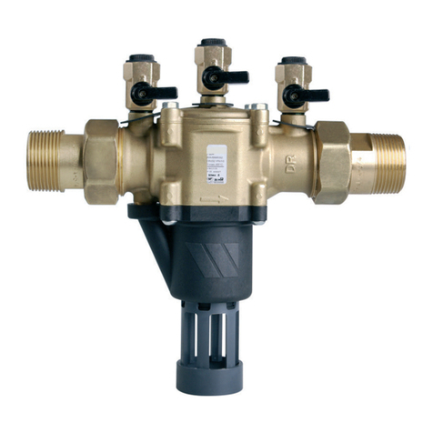
Watts FEBCO 850 Series User manual

IOM-F-FreezeProtection
Installation, Operation and Maintenance Manual
Freeze Protection
Series 850 Small, LF850 Small
Series 860 Small, LF860 Small
½" – 2"
Read this Manual BEFORE using this equipment.
Failure to read and follow all safety and use information
can result in death, serious personal injury, property
damage, or damage to the equipment.
Keep this Manual for future reference.
Local building or plumbing codes may require modifications to
the information provided. You are required to consult the local
building and plumbing codes prior to installation. If the
information provided here is not consistent with local building
or plumbing codes, the local codes should be followed.
This product must be installed by a licensed contractor in
accordance with local codes and ordinances.
Damage from freezing can be costly. FEBCO assemblies are not
warranted against freeze damage. Use the main valve and ball valve
draining procedures to apply freeze protection to Double Check
Valve and Reduced Pressure Zone assemblies.
Guidelines
Backflow prevention assemblies must be protected against freezing for
the winter season in areas where freezing temperatures may occur. If
water inside the assembly freezes, damage to the assembly and the
system may occur.
Proper draining, insulation using heat tape, and heated protective
enclosures are all acceptable methods of freeze protection.
In areas with freezing temperatures, consider installing Series 850U,
860U, LF850U, or LF860U with union end ball valves. The union end
ball valve allows the body of the device to be removed.
When draining an assembly to prevent freezing, remember these
important points:
• The assembly cannot be adequately drained through the test cocks.
For proper draining, follow the Main Valve Draining procedure.
• Drain valves must be added on the inlet and the outlet sides of the
assembly, below the assembly, and preferably below the freeze
line if the remainder of the system is to be drained.
Main Valve Draining
For visual aid information, see Figure 1 when following the Winter
Preparation or the Spring Startup procedure.
Winter Preparation
1. Close the main shutoff valve (A).
2. Open the inlet drain valve (B)
3. Open the inlet and the outlet ball valves (C and D) to the
45 degree (half-open/half-closed) position.
4. Open all test cocks (F).
5. Open the outlet drain valve (E).
6. Remove the cover (G) and the inlet check module until all water
inside the valve drains back through the inlet drain valve (B).
7. Take the followings steps if the piping downstream of the backflow
assembly is blown out with compressed air.
a. Connect the air supply to the outlet drain valve (E) and close the
outlet ball valve (D).
b. After clearing the system with air, partially open the outlet ball
valve (D).
c. Leave all drain valves (E and B), test cocks (F), and ball valves
(C and D) in a half-open/half-closed position for winter.
(For more information, see the Ball Valve Draining procedure.)
d. Make sure the main shutoff valve (A) remains closed and does
not leak.
8. For Reduced Pressure units only. Loosen the relief valve cover (H)
to drain. Tighten the cover when draining is completed.
Spring Startup
When the chance of freeze damage has passed, prepare the
assembly to restore operation.
1. Close all drain valves (E and B), test cocks (F), and ball valves
(C and D).
2. Retighten the relief valve cover (H), then slowly open the main
shutoff valve (A) and the inlet ball valve (C).
3. Slightly open then close all test cocks (F) one at a time to empty
air from the device.
4. Slowly open the outlet ball valve (D) and refill the system.

E
Outlet Drain Valve D
FGFFF
C
H
Valve Pit
B
Inlet
Drain Valve
A
Main
Shutoff Valve
Figure 1. Components of Series 850 and 860 noted in
the Winter Preparation and Spring Startup procedures.
Ball Valve Draining
Ball valves should also be drained for the winter season in areas
where freezing temperatures may occur. If the valve is left in either
the fully open or the fully closed position, water can become trapped
between the ball and the valve body. And if the trapped water
freezes, damage to the ball valve occurs.
After draining procedures on the backflow prevention assembly have
been completed, all ball valves must be left in the half-open/half-closed,
45 degree position. (Observe this position in Figures 2 and 3.)
Figure 2. Ball valve in half-open/half-closed, 45 degree position.
Open the ball valve approximately 45 degrees to allow water
between the ball and the valve body to drain. Leave the ball valve in
this position for the winter season to prevent freeze damage.
Open and close ball valves slowly at all times to prevent damage to
the system.
The valve must be closed before the system is repressurized.
Figure 3. Cutaway drawing of the ball valve in the 45 degree position.
Limited Warranty: FEBCO (the “Company”) warrants each product to be free from defects in material and workmanship under normal usage for a period of one year from the date of original shipment.
In the event of such defects within the warranty period, the Company will, at its option, replace or recondition the product without charge.
THE WARRANTY SET FORTH HEREIN IS GIVEN EXPRESSLY AND IS THE ONLY WARRANTY GIVEN BY THE COMPANY WITH RESPECT TO THE PRODUCT. THE COMPANY MAKES NO OTHER
WARRANTIES, EXPRESS OR IMPLIED. THE COMPANY HEREBY SPECIFICALLY DISCLAIMS ALL OTHER WARRANTIES, EXPRESS OR IMPLIED, INCLUDING BUT NOT LIMITED TO THE IMPLIED
WARRANTIES OF MERCHANTABILITY AND FITNESS FOR A PARTICULAR PURPOSE.
The remedy described in the first paragraph of this warranty shall constitute the sole and exclusive remedy for breach of warranty, and the Company shall not be responsible for any incidental, special
or consequential damages, including without limitation, lost profits or the cost of repairing or replacing other property which is damaged if this product does not work properly, other costs resulting from
labor charges, delays, vandalism, negligence, fouling caused by foreign material, damage from adverse water conditions, chemical, or any other circumstances over which the Company has no control.
This warranty shall be invalidated by any abuse, misuse, misapplication, improper installation or improper maintenance or alteration of the product.
Some States do not allow limitations on how long an implied warranty lasts, and some States do not allow the exclusion or limitation of incidental or consequential damages. Therefore the above
limitations may not apply to you. This Limited Warranty gives you specific legal rights, and you may have other rights that vary from State to State. You should consult applicable state laws to
determine your rights. SO FAR AS IS CONSISTENT WITH APPLICABLE STATE LAW, ANY IMPLIED WARRANTIES THAT MAY NOT BE DISCLAIMED, INCLUDING THE IMPLIED WARRANTIES OF
MERCHANTABILITY AND FITNESS FOR A PARTICULAR PURPOSE, ARE LIMITED IN DURATION TO ONE YEAR FROM THE DATE OF ORIGINAL SHIPMENT.
USA: T: (800) 767-1234 • FEBCOonline.com
Canada: T: (888) 208-8927 • FEBCOonline.ca
Latin America: T: (52) 55-4122-0138 • FEBCOonline.com
IOM-F-FreezeProtection 2344 © 2023 Watts
Other Watts Protection Device manuals
