Wattsense BOX User manual
BOX
Installation Guide
Univers l Buildin
Connector
2020-12-V1.3
Made in France

2020-12-V1.3
1
Table of Contents
What do you need before starting? 2
Provided material 2
Required material 2
Optional hardware depending on the type of connection 3
Computer access to the Wattsense console 3
The power supply of the Box 4
GSM Antenna 9
To connect the Box to the BMS 10
In case of IP network (Except LON) 10
In case of LON IP-852 network 13
In case of LON FT10 network 16
To connect the Box directly to the technical equipment in the absence of a BMS 18
The equipment communicates in Modbus IP 18
The equipment communicates in Modbus RTU (RS485) 23
The equipment communicates in BACnet IP 29
The equipment communicates in LON FT10 33
The equipment communicates in LON IP-852 35
The equipment communicates in LPB 37
To connect the Box to LoRaWAN sensors 40

2020-12-V1.3
2
What do you need before starting?
Provided material
● Box
○ Dimensions: 160 x 110 x 55 mm
○ Weight: 340 g
● GSM standard antenna
● LoRa standard antenna
Required material
● Powerline voltage (100 to 250VAC) to 12V-24V DC +/-10% power supply
● Cable between the power supply and the Box: 2 wires (red, black), 22 AWG,
minimum section: 0.35 mm²
● Flat screwdriver
● Cutting pliers
● Wire stripper

2020-12-V1.3
3
Optional hardware depending on the type of connection
● Bus connection cable: 2 wires, 24 AWG, minimum section: 0.22 mm² + braid
● Ethernet cables
● Ethernet switch
● Echelon U60 FT DIN USB Gateway (for LON FT10)
● High-gain GSM antenna
● High-gain LoRa antenna
● GSM or LoRa antenna cable
● Double-sided high performance adhesive tape
● Technical documentation of equipment
● Technical documentation of IoT sensors
● Schematic of the communication network(s) of the BMS
Computer access to the Wattsense console
● Each customer has a dedicated space on the Wattsense User Console at
https://console.wattsense.com. This interface allows them to manage their fleet of
Boxes.
● A Box must have been activated in advance before it can be fully installed and
configured.
● If the Box hasn’t been activated, ask the administrator of the account to create an
"installation" access on the Wattsense user console and retrieve the login
information (email address and password).
● Once on-site, activate the Box on the console:
○ How to Log in to the console: enter the email and password provided by the
administrator and click on "Log in".
○ Enter the alphanumeric identifier of the Box in the search rectangle at the
top.
○ Click on "Activate".
○ It is required to give the Box a name in the "Name" field (for example, the
name of the site where it will be installed).
○ If necessary, add additional information in the "Description" field in order to
clearly identify the Box (for example the floor or the precise place of
installation if on the same site there are several Boxes).
○ Click on "Activate the Box".
● You will then be able to access the configuration tools.
2020-12-V1.3
4
The power supply of the Box
Make sure that the Box has been activated beforehand on the user console.
● Ideally, place the Box in an electrical enclosure or cabinet.
● This type of equipment is not suitable for installation in places that can
accommodate children.
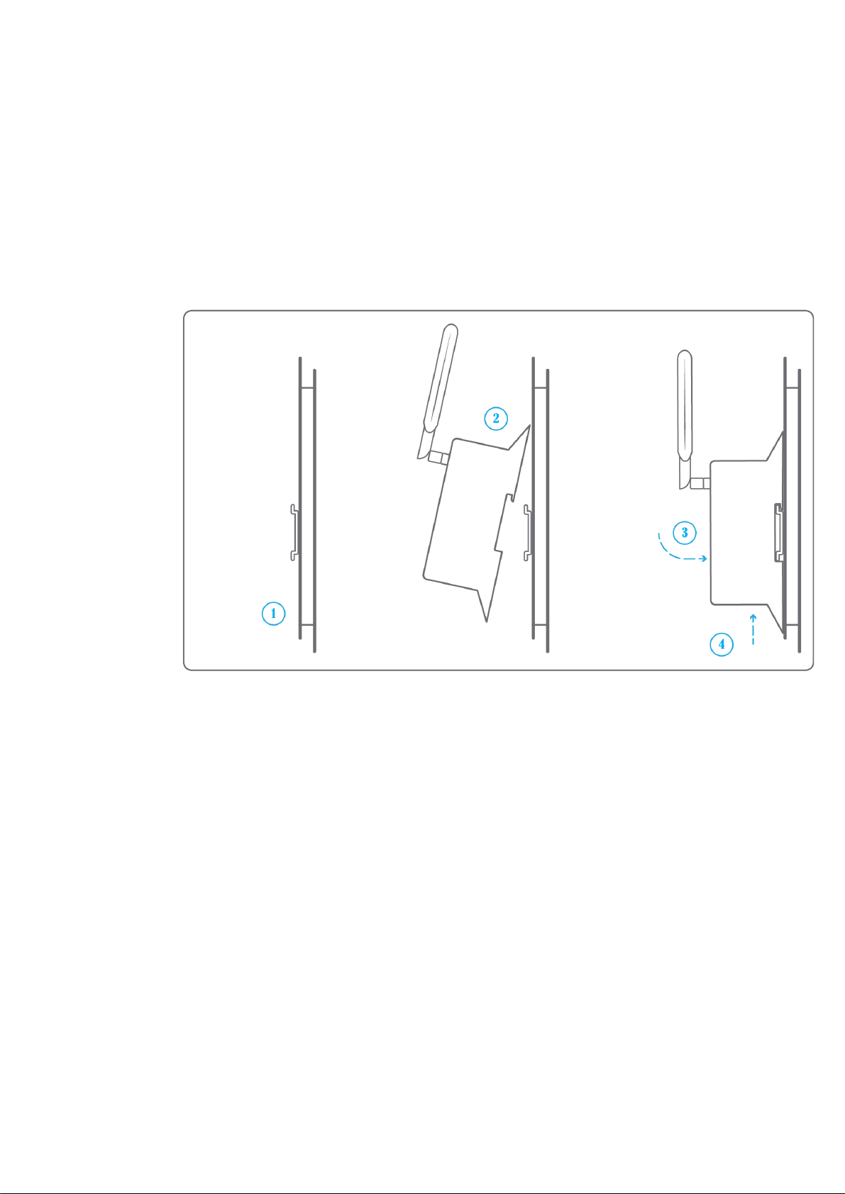
● Attach the Box:
○ Mount the Box on a DIN rail.
○ Or attach 2 screws to a wall and hook the Box using the notches on the back
of the case: Screws of maximum 4 mm in diameter, with a head of maximum
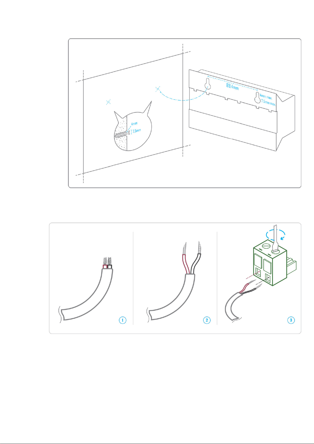
2020-12-V1.3
5
7.5 mm diameter, a spacing of 89.4 mm.
● To avoid any risk of injury caused by the Box falling, the Box must not be installed
more than 2 meters from the ground.
● Use a DC power supply of 12V to 24V +/-10%, 2A.
● Screw the cable into the power connector of the Box.

2020-12-V1.3
6
● Connect the cable to the power supply.
● Check that the "Power" LED is lit (steady green light).

2020-12-V1.3
7
● The Box is protected against overvoltage, undervoltage, overcurrent from the power
supply with indication by LED: green LED when the power supply is compatible, red
LED if it is not suitable.
● Wait for ten seconds: the "Heartbeat" LED flashes (green light).
2020-12-V1.3
8
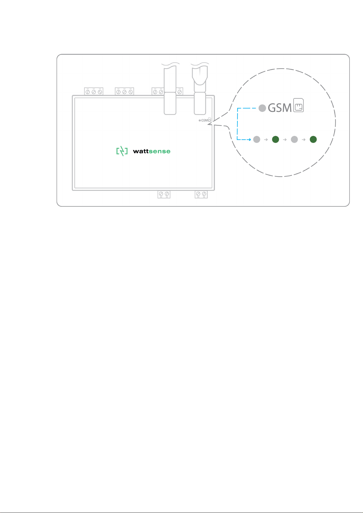
● Wait for the GSM LED to flash; if the LED does not flash after a few minutes, see
the GSM Antenna chapter.
● Check that the Box appears on the console: the presence indicator of the Box
changes from red to green.
● If the Box appears on the console, it is functional; you can go to the connection step
of the Box to the equipment and/or the network of the building.
● If the Box does not appear on the console, see the GSM Antenna chapter.

2020-12-V1.3
9
GSM Antenna
The Box is supplied with a standard GSM antenna.
● If the quality of the GSM signal is good: keep the original antenna installed on the
Box.
● If the signal quality is insufficient: move the original antenna out of the cabinet; use
an RF extension cord with SMA connector, up to 2 meters, + 1 adhesive support to
hold the antenna.
● If the signal quality is still insufficient: use a high-gain antenna with a maximum of
10 meters of cable; this antenna can, for example, be moved to the outside or to the
other floors to obtain a better signal quality. Please note that, beyond 15 meters of
cable, the GSM signal is significantly weakened.
2020-12-V1.3
10
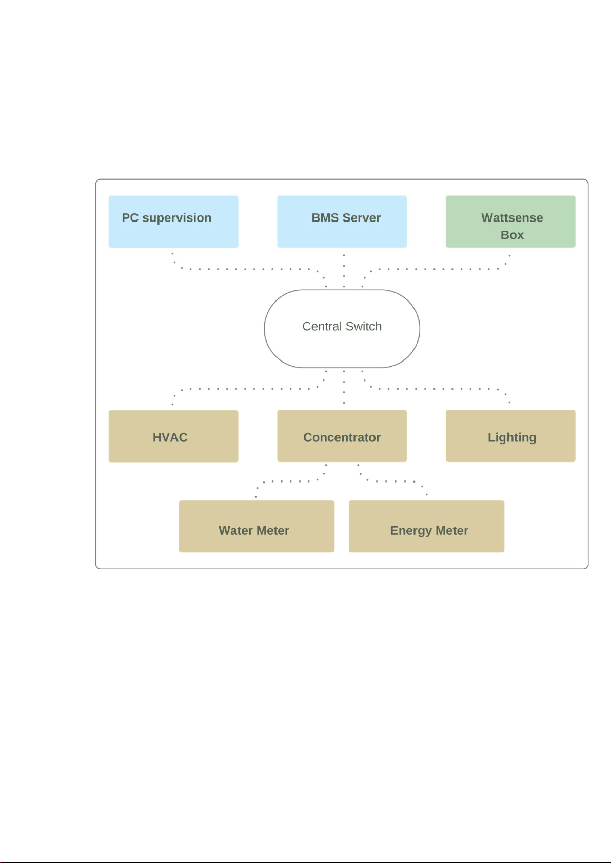
To connect the Box to the BMS
● Determine the type(s) of network(s) associated with the BMS (communication
protocols between the BMS server and the technical equipment).
● Obtain, if possible, the schematic of the communication network(s) of the BMS.
● Identify where and how the BMS server connects to the building’s network.
In case of IP network (Except LON)
Connection:
● Make sure to have an Ethernet cable
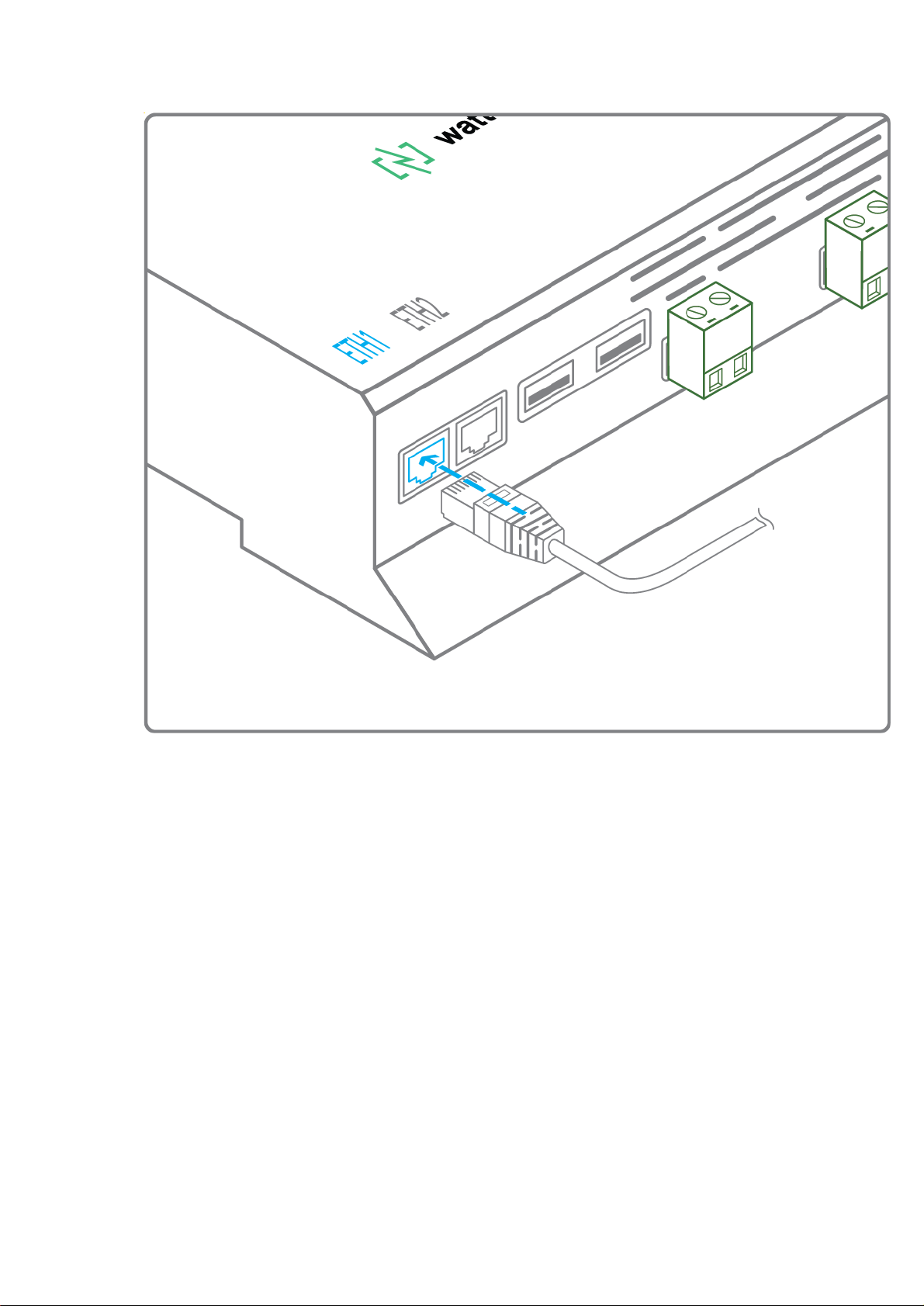
2020-12-V1.3
11
● Connect the cable to the Ethernet port of the Box ETH1 or ETH2.
● Connect the Box to the switch (IP network) on which the supervision PC/BMS
server is connected.

2020-12-V1.3
12
● Check that the ETH1 or ETH2 LED lights up.
Configuration:
● If there is not a DHCP server on the network, attribute a static IP address, its mask
and the gateway if necessary to the Box (Discuss with the building’s IT manager).
● If there is a DHCP server on the network, the address is automatically assigned.
Information to retrieve in preparation for the configuration:
● For each device that communicates in Modbus IP
○ From the BMS software, perform an extract of the available properties: list
the data types provided by the different devices to which the BMS has
access.
○ If it is impossible to retrieve this information, recuperate the IP address and
TCP port (and if needed, for some devices, the slave address (Slave ID), the
brand, and model of the equipment, and extra identifying information. This
information is necessary for the installation configuration and to retrieve data.
● In the case of a BACnet IP network
○ Write down the BACnet port of the network. This information will be
necessary for the installation configuration and to retrieve data.
2020-12-V1.3
13
In case of LON IP-852 network
Connection:
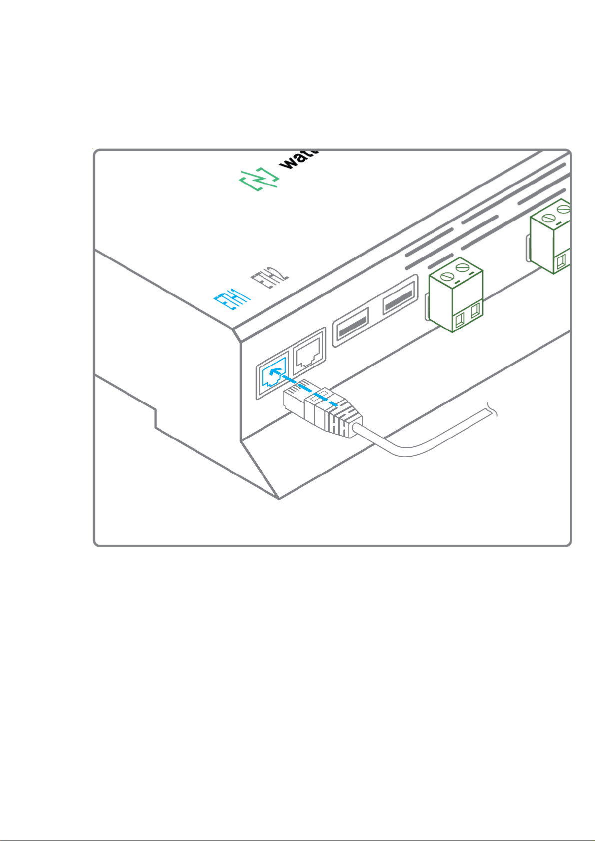
● Make sure to have an Ethernet cable.
● Connect the cable to the Ethernet ports of the Box ETH1 or ETH2.

2020-12-V1.3
14
● Connect the other end of the cable to the IP-852 server on the LON network.

2020-12-V1.3
15
● Verify that the ETH1 or ETH2 LED lights up
● Register the IP address of the Box on the IP-852 server of the LON network; the IP-
852 server’s password is probably required.
Information to retrieve in preparation for the configuration:
● Write down the neuron-ID, brand and model of the equipment, and any identifying
information. This information will be necessary for the installation configuration and
to retrieve data.
● If you have the NL220 software, export the LON database as an archive file or as
an NLC file.
2020-12-V1.3
16
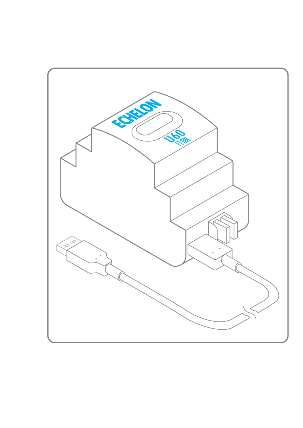
In case of LON FT10 network
Connection:
● Make sure to have a USB Echelon U60 FT DIN gateway.
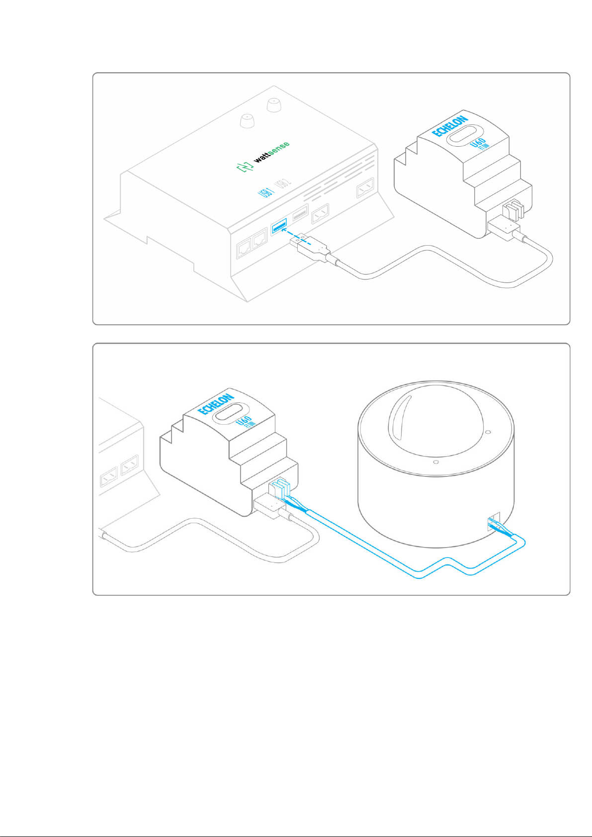
2020-12-V1.3
17
● Connect this gateway to the USB port 1 or 2 of the Box.
● Connect also this gateway to the LON FT10 network.
Information to get in preparation for the configuration:
● Write down the Neuron-ID, brand and model of the equipment, and any identifying
information. This information will be necessary for the installation configuration and
to retrieve data.
● If you have the NL220 software, export the LON database as an archive file or as
an NLC file.

2020-12-V1.3
18
To connect the Box directly to the
technical equipment in the absence of a
BMS
● Prepare the list of equipment to be connected and their respective communication
protocols.
● Collect the technical documentation of each manufacturer to know where and how
to connect to its devices (user console, configuration wizard, manufacturer’s site,
etc.).
● Draw up an installation schematic.
The equipment communicates in Modbus IP
To connect only 1 equipment
● Make sure to have an Ethernet cable.
● Connect the cable to the Ethernet port of the Box ETH1 or ETH2.

2020-12-V1.3
19
● Connect the other end of the cable to the equipment.
● Verify that the ETH1 or ETH2 LED lights up.
To connect 2 devices
● Make sure to have 2 Ethernet cables.
Table of contents
Other Wattsense Cables And Connectors manuals

Popular Cables And Connectors manuals by other brands

VIVIFY
VIVIFY ARQUUS W73 manual

Burndy
Burndy Continental Industries thermOweld CB-18 instructions

Miele
Miele Connector Box Operating and installation instructions

Eaton
Eaton 600 A 35 kV Class Insulated Standoff Bushing installation instructions

GefenTV
GefenTV GTV-HDMI1.3-144 user manual

HARTING
HARTING 21 03 821 1530 Assembly instruction

Whirlwind
Whirlwind Mic Cable WMKPVC Specification sheet

TE Connectivity
TE Connectivity AMP NETCONNECT 1499119-1 instruction sheet

cable matters
cable matters 201046 quick start guide

Converters.TV
Converters.TV 757 Operation manual

Panasonic
Panasonic POVCAM AG-HCK10G Specification sheet

INSIGHT
INSIGHT Wl 53080 Jet Reel Operation Manual


