manuals.online logo
Brands
  1. Home
  2. •
  3. Brands
  4. •
  5. TE Connectivity
  6. •
  7. Cables And Connectors
  8. •
  9. TE Connectivity AMP NETCONNECT 1499119-1 User manual

TE Connectivity AMP NETCONNECT 1499119-1 User manual

Instruction Sheet
©2011 Tyco Electronics Corporation, a TE Connectivity Ltd. Company
All Rights Reserved
*Trademark
TE Connectivity, TE connectivity (logo), and TE (logo) are trademarks. Other logos, product and/or Company names may be trademarks of their respective owners.
1of 3
TOOLING ASSISTANCE CENTER
1-800-722-1111
PRODUCT INFORMATION
1-800-522-6752
This controlled document is subject to change.
For latest revision and Regional Customer Service,
visit our website at www.te.com
LOC B
AMP NETCONNECT* Undercarpet
Communications Cabling System
4-Pair Unshielded Twisted-Pair (UTP) Cable
1499119-1 and -5 and 1499539-1 and -5 408-3194
02 MAY 11 Rev K
Figure 1
1. INTRODUCTION
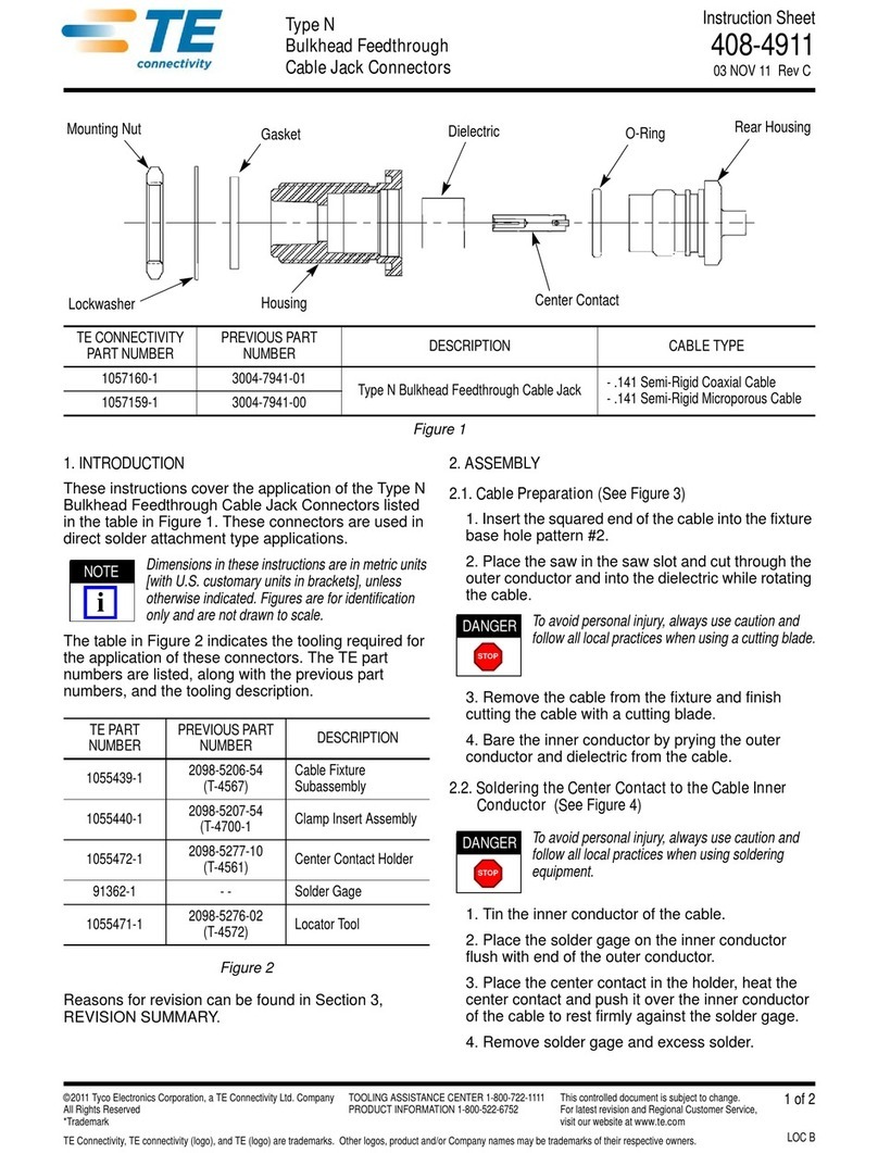
Undercarpet 4-pair UTP cables shown in Figure 1 are
used in undercarpet communications applications.
Dimensions in this instruction sheet are in metric
units [with U.S. customary units in brackets].
Figures are not drawn to scale.
To obtain information on AMP NETCONNECT
products, call PRODUCT INFORMATION at the
number at the bottom of this page, or visit the
AMP NETCONNECT website at
www.ampnetconnect.com.
Reasons for reissue of this instruction sheet are
provided in Section 5, REVISION SUMMARY.
2. DESCRIPTION
The cable is provided on a reel that has a hole in the
center. The cable unwinds with the printed side of the
cable on top. The cable has a wing on each edge with
twisted-pair conductors inside a center rib.
3. INSTALLATION PROCEDURE
IMPORTANT: It is recommended that a qualified
technician install the undercarpet communications
cable.
To avoid personal injury, ALWAYS DISCONNECT
the electrical power before beginning work on any
circuit.
3.1. Planning
Before starting installation, understand the following:
— The communications cable should be installed after
the power cabling system is installed and just prior
to installing the carpet.
— Communications cable runs may cross the power
cable top shield; however, the crossing should not
occur where the power cable is tapped, spliced, or
folded.
— Except at crossings, the communications cable
should NOT run on top of the power cable top
shield or run closer than 152.4 mm [6 in.] to the
power cable top shield.
— DO NOT allow the communications cable to cross
other communications cable.
— If possible, routing of the communications cable
should be planned to avoid high traffic areas and
areas under desk chairs.
3.2. Transition Box, Communications Transition Block,
and Floor Fitting
Install the transition box, communications transition
block, and floor fitting according to the instructions
included with the product.
Instruction sheet included with product is:
408-10336 — Surface Mount Wall Transition Box
408-10412 — Flush Mount Wall Transition Box
408-3368 — Category 5e Communications
Transition Block
408-10009 — Category 6 Communications
Transition Block
408-3179 — Low-Profile Floor Fitting
408-8843 — Multimedia Dual Data Kit
408-3129 — Conductor Direct Connecting
Receptacle (DCR) Kits
3.3. Prepare Floor Surface
Level or patch all uneven floor surfaces. Fill in and
smooth all holes and cracks, and remove all
projections, ensuring a smooth and continuous floor
surface. Seal all porous floors.
The communications cable must be installed onto a
clean and level floor surface.
3.4. Communications Cable
1. Cut a notch in the wall to allow the cable to radius
to the floor.
UNDERCARPET
COMMUNICATIONS
CABLE
LENGTH PERFORMANCE
LEVEL
1499119-1 0.76 m [250 ft] Category 5e
1499119-5 30.5 m [100 ft]
1499539-1 0.76 m [250 ft] Category 6
1499539-5 30.5 m [100 ft]
NOTE
i
AMP NETCONNECT logo is a trademark of TE Connectivity.
DANGER
STOP
NOTE
i
!
CAUTION
20.32 mm [.80 in.]
Internal Diameter
Reel
Printed Side
of Cable
Wings
Conductors
408-3194
2of 3
Rev K
2. Flex the wings of the cable while removing the
cable from the reel.
3. From the distribution point (wall box or floor
fitting), lay the cable on the floor with the printed
side of the cable facing up and the bow of the cable
pointing up. Refer to Figure 2, Detail A.
If more than two cable runs exit the distribution
point, remove the inner wing of each cable, then
place the cables side by side. See Figure 2,
Detail A.
To remove the inner wing, use Cable Notcher Tool
1725698-1 (available separately) to cut a notch to
the groove in the wing; then, flex the wing and tear
it back slowly. DO NOT cut into the center rib
containing the conductors. See Figure 2, Detail B.
4. Place hold-down tape over the cable area. See
Figure 2, Detail A.
Hold-Down Tape 553481-1 is available separately.
5. Cross-tape as required along the cable run.
Stretch the tape to remove any slack.
Spray Adhesive 553453-1 is available separately
and may be used to aid in adhering the tape to the
cable and floor surface.
6. If extra protection for the communications cable is
desired, install Floor Preparation 554123-[ ] and Top
Shield 553536-[ ] according to 408-3150; both are
available separately.
The communications cable does not require a top
shield or bottom shield; however, local inspection
requirements and certain floor finishes are
examples where extra protection for the cable
would be desirable.
7. If the cable requires directional changes, proceed
as follows:
a. Using Cable Notcher Tool 1725698-1, notch
the wings of the cable at 25.4-mm [1.0-in.]
intervals. Make sure to remove all notched
material. Refer to Figure 3, Detail A.
DO NOT cut into the center rib of the cable
containing the conductors.
b. Bend the cable to form a gradual turn. Refer
to Figure 3, Detail B for recommended length
and radius. Cover the turn with hold-down tape
to blend the profile of the cable at the notches.
DO NOT fold the cable. Cable must be notched and
cable bends must be gradual.
Figure 2
8. Terminate the cable to the transition block and
floor fitting outlet according to the instructions
included with the product.
NOTE
i
NOTE
i
NOTE
i
NOTE
i
!
CAUTION
!
CAUTION
Printed Side
of Cable
Bow of Cable
Floor
Detail B
Notch in Wall
Hold-Down
Tape (Ref)
Over Cable
Distribution
Point
1 or 2 Cable Runs
More Than 2 Cable Runs Hold-Down
Tape (Ref)
Over Cable
7.92 mm [.312 in.]
(Typ) Centerline
to Centerline
of Cable
Detail A
Inner Wing
of Cable
Cut Notch Tear Back
Groove
Inner Wing of
Cable Removed
(See Detail B)
Cable
Orienting Communications Cable
Laying Communications Cable
408-3194
3of 3
Rev K
Figure 3
4. REPLACEMENT AND REPAIR
The undercarpet communications cable is not
repairable. DO NOT use any defective or damaged
cable.
5. REVISION SUMMARY
Revisions to this instruction sheet include:
•Changed company logo
•Added
undercarpet communications cabling, 4-pair,
UTP, and cable part numbers to title of instruction
sheet
•Removed UL reference from Section 1
•Modified Figures 1 and 4 and Sections 2, 3, and 4
and combined Sections 3 and 4
•Removed Figures 2 and 6
•Added Paragraphs 3.1 and 3.2
•Removed centerline spacing from Figure 2,
Detail A
•Replaced Section 5 with Step 6 of Paragraph 3.4
Detail A
Detail B
25.4 mm [1.0 in.]
(Centerline) Notch Intervals
Communications Cable Conductors
(Ref)
406.4 mm [16.0 in.] Min
Notched Area
25.4 mm [10.0 in.] Min
Radius Bend in Cable
Hold-Down
Tape (Ref)
Hold-Down
TapeCovering
Turn

This manual suits for next models

3

Other TE Connectivity Cables And Connectors manuals

TE Connectivity SolderSleeve CWT Series Reference guide

TE Connectivity

TE Connectivity SolderSleeve CWT Series Reference guide

TE Connectivity M12 User guide

TE Connectivity

TE Connectivity M12 User guide

TE Connectivity VAL-U-LOK 3-1586040-6 User manual

TE Connectivity

TE Connectivity VAL-U-LOK 3-1586040-6 User manual

TE Connectivity LJSU-4X Series User manual

TE Connectivity

TE Connectivity LJSU-4X Series User manual

TE Connectivity CCS1 User manual

TE Connectivity

TE Connectivity CCS1 User manual

TE Connectivity D5000-S User manual

TE Connectivity

TE Connectivity D5000-S User manual

TE Connectivity HVP800 2PHI 90 User manual

TE Connectivity

TE Connectivity HVP800 2PHI 90 User manual

TE Connectivity DRC16 User manual

TE Connectivity

TE Connectivity DRC16 User manual

TE Connectivity HVA630-2phm User manual

TE Connectivity

TE Connectivity HVA630-2phm User manual

TE Connectivity GS-IPC-500U User manual

TE Connectivity

TE Connectivity GS-IPC-500U User manual

TE Connectivity Miniature AMP-IN User guide

TE Connectivity

TE Connectivity Miniature AMP-IN User guide

TE Connectivity 025/250 User manual

TE Connectivity

TE Connectivity 025/250 User manual

TE Connectivity DYNAMIC 5000 Series User manual

TE Connectivity

TE Connectivity DYNAMIC 5000 Series User manual

TE Connectivity 55PC1122-16-9/96-9 User manual

TE Connectivity

TE Connectivity 55PC1122-16-9/96-9 User manual

TE Connectivity QSFP-DD User guide

TE Connectivity

TE Connectivity QSFP-DD User guide

TE Connectivity RF COAXIAL User manual

TE Connectivity

TE Connectivity RF COAXIAL User manual

TE Connectivity AMP-HDI User manual

TE Connectivity

TE Connectivity AMP-HDI User manual

TE Connectivity AMPOWER 68361-1 User manual

TE Connectivity

TE Connectivity AMPOWER 68361-1 User manual

TE Connectivity AMPLIMITE HDP-20 User manual

TE Connectivity

TE Connectivity AMPLIMITE HDP-20 User manual

TE Connectivity TNC COAXICON Series User manual

TE Connectivity

TE Connectivity TNC COAXICON Series User manual

TE Connectivity AMPACT 83452 Series User manual

TE Connectivity

TE Connectivity AMPACT 83452 Series User manual

TE Connectivity MATE-N-LOK 2 794216-1 User manual

TE Connectivity

TE Connectivity MATE-N-LOK 2 794216-1 User manual

TE Connectivity 747564-9 User manual

TE Connectivity

TE Connectivity 747564-9 User manual

TE Connectivity Quadrax DSub User guide

TE Connectivity

TE Connectivity Quadrax DSub User guide

Popular Cables And Connectors manuals by other brands

Shinybow USA ANI-0108HC user guide

Shinybow USA

Shinybow USA ANI-0108HC user guide

Monster iCruze MPC FX IC-BMW2 Installation & user guide

Monster

Monster iCruze MPC FX IC-BMW2 Installation & user guide

EXEL ACOUSTICS tecnare TPB1U Operation manual

EXEL ACOUSTICS

EXEL ACOUSTICS tecnare TPB1U Operation manual

GoMax Electronics SP-5564 user manual

GoMax Electronics

GoMax Electronics SP-5564 user manual

TRENDnet TU2-DU5 Specifications

TRENDnet

TRENDnet TU2-DU5 Specifications

KIFCO AG-RAIN Water-Reel T30A Operator's manual

KIFCO

KIFCO AG-RAIN Water-Reel T30A Operator's manual

ODU MINI-SNAP F Series Assembly instructions

ODU

ODU MINI-SNAP F Series Assembly instructions

Microsoft K08-00001 instructions

Microsoft

Microsoft K08-00001 instructions

TERK Technologies BSP-2 Connections & Warranty

TERK Technologies

TERK Technologies BSP-2 Connections & Warranty

NEUTRIK SpeakON SPX Series Assembly instruction

NEUTRIK

NEUTRIK SpeakON SPX Series Assembly instruction

KILLARK MCX Series Installation, operation & maintenance manual

KILLARK

KILLARK MCX Series Installation, operation & maintenance manual

SIIG CE-DV0031-S1 Quick installation guide

SIIG

SIIG CE-DV0031-S1 Quick installation guide

Würth 0772 025 350 Instructions for use

Würth

Würth 0772 025 350 Instructions for use

Weidmüller STEADYTEC IE-TO-RJ45-FJ-A Mounting Information

Weidmüller

Weidmüller STEADYTEC IE-TO-RJ45-FJ-A Mounting Information

GPS S14W user manual

GPS

GPS S14W user manual

Philips SWV3567 Specifications

Philips

Philips SWV3567 Specifications

SMC Networks Tiger Access Extended Ethernet Splitter... Brochure & specs

SMC Networks

SMC Networks Tiger Access Extended Ethernet Splitter... Brochure & specs

Festo NEBU-M8R3 Series Assembly instructions

Festo

Festo NEBU-M8R3 Series Assembly instructions

manuals.online logo
manuals.online logoBrands
  • About & Mission
  • Contact us
  • Privacy Policy
  • Terms and Conditions

Copyright 2025 Manuals.Online. All Rights Reserved.