manuals.online logo
Brands
  1. Home
  2. •
  3. Brands
  4. •
  5. Wave wifi
  6. •
  7. Network Router
  8. •
  9. Wave wifi EC Series User manual

Wave wifi EC Series User manual

EC-Series Mobile Wi-Fi Products -Quick Start Guide
Logging-in to the EC Unit
Ideal antenna
mounting location
The EC-unit is supplied with an LMR-400
antenna cable 25-feet long. This cable
should not be substituted with a
different type or different length of
cable. Substituting the cable supplied
may reduce the transmission distance
dramatically.
The EC-AP has a local access point
antenna on top of the case, this is a low
gain omni-directional antenna. This
antenna can be replaced by a high gain
directional antenna, such as a patch
antenna. The antenna connector is an
industry standard RP-TNC.
It is recommended that installation work be carried out by a qualified electronics technician. The EC-unit may
be damaged by incorrect installation. The warranty does not cover damage through incorrect power wiring.
A high gain omni-directional antenna is shipped with the EC
unit for connection to the bridge radio. This is the N connector
located on the lower side of the case. The antenna should be
mounted in a high vertical position so that it is
vertically
polarized
.
EC-HP configuration
Marin e
Backhaul
antenna
10dBi gain
Laptop computer
Ethern et cat-5
X-over cable
DC powe r
12v to 30v
EC-AP and EC-AP-HP
configuration
Mari n e
backhaul
antenna
10dBi gain
Ethern et cat-5
X-over cabl e
DC powe r
12v to 30v
Local
access
point
antenna
Laptop computer
Laptop computer
Connected to the
EC-AP via wire less
EC-AP and EC-AP-HP
configuration
Mari n e
backhaul
antenna
10dBi gain
Ethern et cat-5
X-over cabl e
DC powe r
12v to 30v
Local
access
point
antenna
Laptop computer
Laptop computer
Connected to the
EC-AP via wire less
Power supply 12
to 24 vol ts –
negative ground
EC-series unit
Red wire
Bla ck w ire
Line fuse
2 AMPS
12v
Batte ry
Breaker
Power supply 12
to 24 vol ts –
negative ground
EC-series unit
Red wire
Bla ck w ire
Line fuse
2 AMPS
12v
Batte ry
Breaker
The EC-HP is a ship to shore Ethernet bridge. Computers connected to the Ethernet network can scan for, and
connect to, hot-spots that provide a pathway to the Internet. The EC-AP-HP has an additional access point so
that the computers on the ship can access the Internet wirelessly. If you need more information than this
Rapid Start Guide provides then please see the comprehensive manual available on CD shipped with this
product.
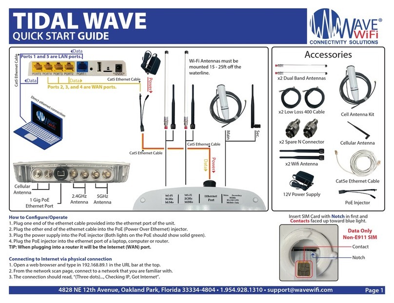
Connect your computer Ethernet port to the EC-unit Ethernet cable. When
the computer has obtained an IP address from the EC-unit, open the
browser. You can check that your computer has an IP address by opening
your computer’s network icon, then see if it is ‘connected’. The browser
can be MS Internet Explorer, Firefox or Netscape.
After a short delay, the network scan page will open. The web page will
look like the one shown below.
EC-series products are wired into the ship’s low voltage supply:
12 volts or 24 volts. Include a line fuse and breaker, and take
care with polarity of the DC wires. The EC unit can also be
connected to a 110 volt supply using a switching power supply.
Please call Wave WiFi for information.
If you are connecting wirelessly to an EC-AP unit then you should look for
the wireless network with the name:
Wave WiFi EC Series
IF your computer is not already connected to this network then click on
CONNECT. Once connected then open your browser with the URL above
Now that you are able to connect your computer to the EC-unit then a few
simple configuration steps are required. Please turn this page over to
proceed.
EC-series Mobile Wi-Fi Products - Quick Start Guide
Scanning for Hot-Spot Networks Configuring the EC Bridge Interface
Configuring the EC-AP-HP Local Access
Point
The EC-HP should be ready to connect to remote
networks. The EC-AP-HP however requires that the local
access point be configured. Select MANAGE LOCAL
ACCESS POINT, from the MENU. When this button is
clicked, the page shown below appears.
First of all, enter the access point name, type in the
name of your boat so that you can recognize the access
point. The transmit channel can be left at default unless
the network becomes slow due to conflicts with a nearby
access point. If the local network is to be encrypted then
enter the WEP key as shown.
The changes will only be saved if the CHANGE SETTINGS
button is clicked. After this is clicked, the EC unit may
take up to 2 minutes to restart.
Click on the button CLICK TO RESCAN FOR NETWORKS as
shown on the screen below. A list will appear below the
button showing the networks that have been found.
Because the protocol handshake between the EC unit and a
remote access point can take from 30 seconds to two
minutes, wait two minutes and click the button again. It is
likely that additional networks will be listed.
The list of HotSpot wireless networks is ordered by signal
strength: the strongest signals are indicated by the color
and length of the bar display. It is likely that with
subsequent scans, the bottom of the list may change
frequently due to the weak signal strength of the access
points. All other functions of the EC unit are accessed
through the menu at the top right of the screen
In some cases it is not possible to log-in to the HotSpot
access point because it has been configured in a non-
standard way. In this case, the Bridge Interface
configuration can be changed to gain HotSpot access.
To select the HotSpot network with which you want to
connect, click on the HotSpot name (SSID). This is shown
in the left hand column. The EC-unit will negotiate a
connection with the remote HotSpot. During this process
the timer will be counting as shown on the screen below.
Do not click on anything until this process is completed. If
the HotSpot access point is able to provide an IP address
to the EC unit then the red NO in the IP column will
change to a green YES.
Clicking on EC NETWORK SETTINGS on the scan page
opens the screen below. DISABLE EC FIREWALL
removes your protection from access by other network
users. However, it may be necessary to disable this
feature to access some HotSpots where the access
point has been configured incorrectly. USE STATIC IP
ADDRESS may be necessary for some HotSpots where
access is billed and controlled by giving users IP
addresses.
Reset Network Settings when Moving Between
Networks
If you had connected to the EC-AP-HP unit wirelessly then
your computer wireless card will have disconnected from
the EC-AP-HP. Go to the computer wireless configuration
screen and look for the new wireless network name that
you installed.
When the configuration is complete, click on the MENU
button NETWORK SCAN at the top of the page.
The function of the RESET NETWORK SETTINGS button
is to clear HotSpot information from the EC unit’s
internal registers. As the EC scans for networks and
connects to networks, information about the networks is
stored in internal memory. Click on RESET NETWORK
SETTINGS when moving to a different geographic area.
This will facilitate the search for new networks.

This manual suits for next models

1

Other Wave wifi Network Router manuals

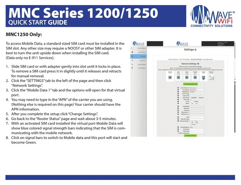
Wave wifi MNC Series User manual

Wave wifi

Wave wifi MNC Series User manual

Wave wifi TIDAL WAVE User manual

Wave wifi

Wave wifi TIDAL WAVE User manual

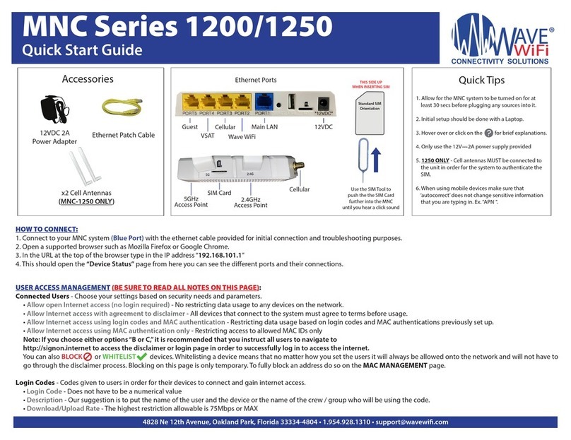
Wave wifi MNC-1200 User manual

Wave wifi

Wave wifi MNC-1200 User manual

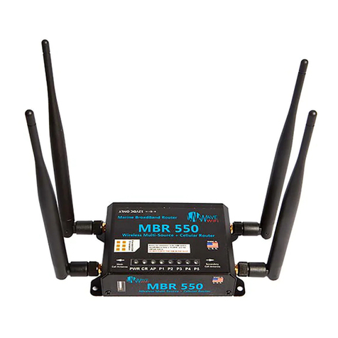
Wave wifi MBR Series User manual

Wave wifi

Wave wifi MBR Series User manual

Popular Network Router manuals by other brands

Atlantis Land WebShare A02-RA11 user manual

Atlantis Land

Atlantis Land WebShare A02-RA11 user manual

Avaya VSP 4850GTS Series Installing

Avaya

Avaya VSP 4850GTS Series Installing

CTC Union FSW3208M user manual

CTC Union

CTC Union FSW3208M user manual

ORiNG IES-3082GC user manual

ORiNG

ORiNG IES-3082GC user manual

Allied Telesis AT AT-GS900/24 datasheet

Allied Telesis

Allied Telesis AT AT-GS900/24 datasheet

Allen-Bradley Stratix 6000 user manual

Allen-Bradley

Allen-Bradley Stratix 6000 user manual

NETGEAR XS512EM Installation

NETGEAR

NETGEAR XS512EM Installation

vpacket 5100 Series Reference manual

vpacket

vpacket 5100 Series Reference manual

Cisco NCS 6008 manual

Cisco

Cisco NCS 6008 manual

Linksys RVS4000 user guide

Linksys

Linksys RVS4000 user guide

ZyXEL Communications P-660R-D Series user guide

ZyXEL Communications

ZyXEL Communications P-660R-D Series user guide

ModemSupply MS51p1 user manual

ModemSupply

ModemSupply MS51p1 user manual

eTung ER-800 user manual

eTung

eTung ER-800 user manual

Allied Telesis AR750S-DP Installation and safety guide

Allied Telesis

Allied Telesis AR750S-DP Installation and safety guide

Flying Voice Technology FWR7102 user guide

Flying Voice Technology

Flying Voice Technology FWR7102 user guide

Linksys Velop MX4000 Series Getting Start

Linksys

Linksys Velop MX4000 Series Getting Start

ProCurve J8463A quick start guide

ProCurve

ProCurve J8463A quick start guide

D-Link DSL-504T user manual

D-Link

D-Link DSL-504T user manual

manuals.online logo
manuals.online logoBrands
  • About & Mission
  • Contact us
  • Privacy Policy
  • Terms and Conditions

Copyright 2025 Manuals.Online. All Rights Reserved.