Wavelength Electronics LDTC0520 User manual

ORDERING INFORMATION
PART NO DESCRIPTION
LDTC0520 500 mA LD / ±2.2 A TEC Controller
LDTC1020 1.0 A LD / ±2.2 A TEC Controller
MULTI-HTSK Heatsink for LDTCxx20
HTSK-BRKT Mounting bracket for MULTI-HTSK
PROVEN RELIABILITY
SAVES YOU TIME AND MONEY
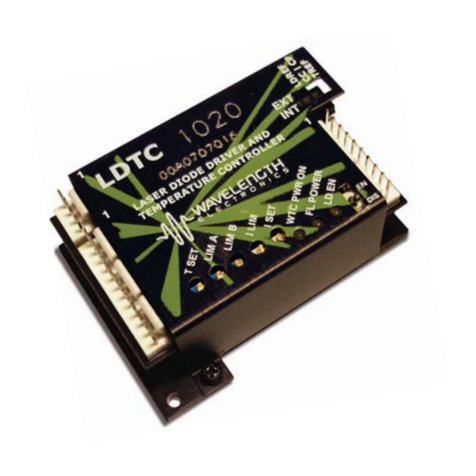
The LDTC Laser Diode and Temperature Controller
combines the proprietary FL500 and ultra-stable WTC3243
in one compact and easy-to-use module. All the controls and
indicators are onboard for simple plug-and-play operation.
APPLICATIONS
LDTC modules are in use around the world providing
POWER YOUR APPLICATION WITH
THE RIGHT FEATURES
The popular FL500 is known for trouble-free operation.
The current limit circuit cleanly clamps laser diode current
a phase shift in a modulated laser signal.
The WTC3243 ultra-stable temperature control module is
known for precision and reliability. Independent cooling-
and heating-current limits allow the LDTC to be used with
FEATURES AND BENEFITS
• Small package size
• Single or dual supply operation
• LD current range 500 mA or 1 A
• Compatible with Type A and B lasers
• Slow start laser diode protection
• Constant Current or Constant Power modes
• Adjustable laser diode current limit
• Brownout protection
• Drive up to ±2.2 A of TEC current
• Internal or External setpoint control
• Failsafe setpoint default
• Ultra-stable PI control loop
• Separate heat & cool current limits
e
PAGE
Applies to Product Revisions A – C
© October 2018
Pb
RoHS
Compliant
CONTENTS
QUICK CONNECT GUIDE 2
PIN DESCRIPTIONS 4
ELECTRICAL SPECIFICATIONS 6
SAFETY INFORMATION &
THERMAL DESIGN CONSIDERATIONS 8
OPERATING INSTRUCTIONS
TEMPERATURE CONTROLLER 9
LASER DRIVER 13
ADDITIONAL TECHNICAL INFORMATION 15
TROUBLESHOOTING
TEMPERATURE CONTROLLER 22
LASER DRIVER 23
MECHANICAL SPECIFICATIONS 25
CERTIFICATION AND WARRANTY 26
406-587-4910
www.teamWavelength.com
LDTC0520/LDTC1020
Laser Diode & Temperature Controllers
DATASHEET AND OPERATING GUIDE

© 2018 www.teamWavelength.com 2
LDTC0520 / LDTC1020 LASER DIODE AND TEMPERATURE CONTROLLER
J1
J2
J3
Status LEDs
Laser Current Enable
Laser Current Setpoint
Laser Current Limit
Temperature Current Limit B
Temperature Setpoint
Temperature Current Limit A
DIP Switches *
DIP Switch Functions
LDREF = Internal vs. External Laser Diode Setpoint
CC | CP = Constant Current vs. Constant Power Control Mode
TREF = Internal vs. External Temperature Setpoint
* DO NOT CHANGE SWITCH POSITIONS WHILE THE OUTPUT
IS ENABLED; DOING SO MAY DAMAGE THE LOAD.
!
Figure 1. LDTCxx20 Top View
QUICK CONNECT GUIDE
!
Laser Diode Drivers:
www.teamwavelength.com/support/design-tools/soa-ld-calculator/
Temperature Controllers:
www.teamwavelength.com/support/design-tools/soa-tc-calculator/
The model number is stamped on the top cover of the
single FL500 on the top; the LDTC1020 has two FL500
Figure 1 gives a top view.
Figure 2
but will not drive Type C lasers; see Figure 3.
VDD_FL
VDD_WTC
VS
GND
SP1
SP2
LD SHD (Enable LD current)
COM
EXT LD SETpoint
COM
LD P Monitor
LD I Monitor
ACT T Monitor
SET T Monitor
EXT T SETpoint
COM
LDC
PDA
Spare
LDA
COM
TEC+
TEC-
SEN+
SEN-
COM
J1
J2
J3
VDD_WTC
VDD_FL
VS
- +
See Note
Thermistor
DVM
OPEN or 3 to 5 V = DISABLE
GND = LD ENABLE
NOTE: Output current to the laser is disabled unless Pin J2:3 is grounded and the on-board switch is enabled.
1
1
4
12
1
10
Optional Laser Current
External Setpoint (0 to 2 V)
Optional
Temp Control
Ext. Setpoint
1
1
2
3
1
1. VDD_WTC, VDD_FL, and VScan be tied together if common voltage provides sufficient compliance for laser diode and
thermoelectric loads. Separate VSif higher compliance is required for the temperature controller load.
2. If using the LD SHD input, set the onboard Enable/Disable switch to Enable.
3. Refer to Electrical Specifications for input voltage range.
3
!THE LDTC DOES NOT SUPPORT LASER DIODE
PACKAGES THAT INCORPORATE A BUILT-IN
TEMPERATURE SENSOR THAT IS CONNECTED
TO THE LASER CASE GROUND.
Figure 2. LDTCxx20 Quick Connect Wiring Diagram
Type A Laser Diode Type B Laser Diode Type C Laser Diode
Common
Cathode
Laser Diode Anode &
Photodiode Cathode Common Isolated Photodiode
Short the
Laser Diode Anode
to Photodiode Cathode
Common
Anode
Laser Diode Cathode &
Photodiode Anode Common
Figure 3. Laser Type Diagrams

© 2018 www.teamWavelength.com 3
LDTC0520 / LDTC1020 LASER DIODE AND TEMPERATURE CONTROLLER
RECOMMENDED TEST LOADS
until familiar with the controller operation. To pre-test or
loads.
Laser Diode Driver:
loads are dependent on operation mode. The test load for
Constant Current mode is shown in Figure 4 and the test
load for Constant Power mode is shown in Figure 5.
1N4001
1N4001
LDC
(Pin J3-1)
LDA
(Pin J3-4)
1 Ω, 2 W
Constant Current Mode
Figure 4. Constant Current Mode Test Load
24 Ω
1N4001
1N4001
2N3906
0.33 µF
PDA
(Pin J3-2)
LDA
(Pin J3-4)
LDC
(Pin J3-1)
Constant Power Mode
The 24 Ω resistor typically
produces approximately 30 mA
laser driver current. Vary the
resistor value to change the
output current.
1 Ω, 2 W
Figure 5. Constant Power Mode Test Load
NOTE:
ammeter in series with the output circuit; doing so may
cause instability in the control loop. To stay within the Safe
Smust not exceed
Temperature Controller:
thermoelectric and thermistor circuits are shown in Figure 6
and Figure 7
test loads is recommended for setting the thermoelectric
controller limits or to check the temperature controller
operation.
R
LOAD
TEC+
(Pin J3-6)
TEC-
(Pin J3-7)
R
LOAD
= 1 Ω, Rated >10 W
Thermal Test Load
I
METER
Figure 6. Simulated Thermoelectric Test Load
R1
R1 = 10 kΩ, ¼ W resistor
SEN-
(Pin J3-9)
SEN+
(Pin J3-8)
Simulated Thermistor
Figure 7. Simulated Thermistor
NOTE: To stay within the Safe Operating Area while using
S

© 2018 www.teamWavelength.com 4
LDTC0520 / LDTC1020 LASER DIODE AND TEMPERATURE CONTROLLER
PIN DESCRIPTIONS
Table 1. Pin Descriptions and Wire Colors
PIN NAME CABLE
COLOR PIN DESCRIPTION
Connector J1, Cable WCB303 (included with LDTC0520 and LDTC1020)
1DD_FL Green
the laser diode forward current plus the driver quiescent current. Low-noise switching power supply
recommended. Reference the Safe Operating Area calculator.
2DD_WTC Red
noise switching power supply recommended. Reference the Safe Operating Area calculator.
3SWhite
1.1-times the TEC maximum drive current. Low-noise switching power supply recommended.
Reference the Safe Operating Area calculator.
4 GND Black Power supply ground.
This is the only ground connection designed as a high current power supply return.
Connector J2, Cable WCB302 (included with LDTC0520 and LDTC1020)
1 SP1 — No connection
2 SP2 — No connection
3 LD SHD Red
Laser diode shutdown / interlock input. The onboard Enable switch must be set to ENABLE when
this external enable function is used. TTL-compatible.
4 COM Green/Blk Do not use for high current return.
5 EXT LD SET White
shown in Table 2. Set the LDREF switch to EXT to reference this input signal. The EXT LD SET
voltage does not sum with the onboard trimpot setting. Not TTL-compatible.
6 COM Green Do not use for high current return.
7 LD P M Orange/Blk Photodiode current monitor output. The signal on this pin is proportional to the photodiode current.
Table 2.
8 LD I M Blue Laser current monitor output. The signal on this pin is proportional to the actual laser output current.
Transfer function shown in Table 2.
9ACT T M Red/Blk Actual temperature sensor voltage monitor output. Output voltage equals the voltage drop across
DD_WTC.
10 SET T M White/Blk Temperature setpoint voltage monitor output. Output voltage equals the temperature sensor
setpoint voltage set by the onboard trimpot or the EXT T SET input.
11 EXT T SET Orange
DD_WTC
Transfer function shown in Table 2. This voltage does not sum with the onboard trimpot setting.
Set the TREF switch to EXT to reference the EXT T SET input signal. Not TTL-compatible. If the
12 COM Black Do not use for high current return.
Connector J3, Cable WCB301 (included with LDTC0520 and LDTC1020)
1 LDC Black Laser diode cathode connection
2 PDA White Photodiode anode connection
3 SP3 Blue No connection
4 LDA Red Laser diode anode connection
5 COM Green Do not use for high current return.
6 TEC+ Red/Blk
Refer
to the operating instructions for proper connections to a TEC or Resistive Heater based on
the type of sensor being used.
7 TEC– Orange
8 SEN+ White/Blk Positive side of temperature sensor. Bias current is driven from SEN+ to SEN–.
9 SEN– Orange/Blk
range. Do not use for high current return.
10 COM Green/Blk Do not use for high current return.

© 2018 www.teamWavelength.com 5
LDTC0520 / LDTC1020 LASER DIODE AND TEMPERATURE CONTROLLER
Table 2. Control and Monitor Transfer Functions
FUNCTION LDTC0520 LDTC1020 DESCRIPTION
External setpoint input to control the laser drive current in Constant
Current mode.
External setpoint input to control the photodiode current in Constant
Power mode.
LD P MON
resistor on the circuit board. Contact the factory for details.
LD I MON The laser current monitor indicates the current driven to the laser.
ILIM Refer to page 20 for location of the ILIM test point on the circuit board.
ACT T M The ACT T M voltage matches the voltage drop across the temperature
sensor.
SET T M The SET T M voltage matches the setpoint voltage set by the onboard
EXT T SET The external temperature setpoint input.
Table 3. Wiring Diagram Reference and LIM Trimpot Functions
SENSOR TYPE LOAD
TYPE
VDD_WTC AND VS
TIED FIGURE, PAGE LIM A TRIMPOT LIM B TRIMPOT
NTC
TEC Either Figure 11 on page 12 Cooling Current Limit Heating Current Limit
Heater* Yes Figure 15 on page 16 Heating Current Limit
No Figure 16 on page 16
PTC
TEC Either Figure 17 on page 16 Heating Current Limit Cooling Current Limit
Heater* Yes Figure 18 on page 16 Heating Current Limit
No Figure 19 on page 16
* Setting the LIM A and LIM B trimpots requires a special procedure when using a resistive heater.

© 2018 www.teamWavelength.com 6
LDTC0520 / LDTC1020 LASER DIODE AND TEMPERATURE CONTROLLER
ELECTRICAL SPECIFICATIONS
ABSOLUTE MAXIMUM RATINGS SYMBOL LDTC0520 LDTC1020 UNIT NOTE
DD_FL 3 to 12
DD_WTC 4.5 to 12
S4.5 to 30
Max LD Output Current ILD 505 1010 mA
Max TC Output Current ITEC ±2.2 A
Laser Driver Internal Power Dissipation1PLD_MAX 2 4 W TAMBIENT = 25ºC 1
Temp Controller Internal Power Dissipation PTC_MAX 9 W
Case Operating Temperature TOPR -40 to 85 ºC
Case Storage Temperature TSTG -55 to 125 ºC
Weight 3.04 3.13 oz
Size 2.9 × 2.35 × 1.08 inches 73.6 × 59.7 × 27.3 mm
LASER DRIVER
SPECIFICATIONS SYMBOL LDTC0520 LDTC1020 UNIT NOTE
CONSTANT CURRENT CONTROL
35 to 40 ppm TAMBIENT = 25ºC
50 to 75 ppm TAMBIENT = 25ºC
CONSTANT POWER CONTROL
0.019 % TAMBIENT = 25ºC
0.011 % TAMBIENT = 25ºC
OUTPUT
Peak Current IMAX 495 to 505 990 to 1010 mA
DD_FLEXT LD SET IMAX = 500 mA
Rise Time 300 nsec ILD = 500 mA
Fall Time 300 nsec ILD = 500 mA
2500 kHz Sinewave input signal
Delayed Start 100 msec
Slow Start Ramp 15 mA / msec
Depth of Modulation 99 % 100 kHz sinewave
LD POWER SUPPLY
DD_FL 3 to 12
DD_FL 2.2 to 4.6 4.4 to 9.2 mA
EXT LD SET INPUT
Input Impedance 5
EXT LD SET 0 to 2
Damage Threshold EXT LD SETDD_FL + 0.3
NOISE
7.5 22 µA RMS ILD = 100 mA; 100 kHz bandwidth
Leakage Current
1
0.2
0.3
mA
EXT LD SET
EXT LD SET
EXT LD SET
1
2
bandwidth in Constant Current mode because of the frequency response of the photodiode.

© 2018 www.teamWavelength.com 7
LDTC0520 / LDTC1020 LASER DIODE AND TEMPERATURE CONTROLLER
ELECTRICAL SPECIFICATIONS (CONTINUED)
TEMPERATURE CONTROLLER
SPECIFICATIONS MIN TYP MAX UNIT NOTE
OUTPUT CURRENT
Max Output Current ±2.0 ±2.2 A
S- 0.7 S- 0.5 TEC = 100 mA
S- 1.2 S- 1.0 TEC = 1 A
S- 1.6 S- 1.4 TEC = 1.5 A
S- 1.8 S- 1.6 TEC = 2 A
S- 1.7 S- 1.6 TEC = 2 A
10.001 0.002 0.010 ºC
10.005 ºC
10.003 0.008 0.010 ºC
TC POWER SUPPLY
DD_WTC 4.5 12
DD_WTC 55 105 mA
S4.5 30
S20 50 100 mA
TEMPERATURE SENSORS
Sensor Compatibility
2 DD_WTC
Sensor Input Damage Threshold 3.6
Sensor Bias Current Selection 2 µA to 1 mA Adjustable
SETPOINT AND MONITORS
30 to 4 Product Revision C
EXT T SET Input Impedance 1
0 to 3.3
EXT T SET Input Damage Threshold 0 to 3.6
Setpoint vs. Actual Temperature Accuracy 0.1 2 4 TSET
FEEDBACK LOOP
18 20 22
2 3 4.5 sec
1
above ambient.
2DD_WTC
DD_WTC
the controller will not provide proper control under these conditions.
3
C
SDD_FL
WTC3243 at www.teamwavelength.com/support/design-tools/soa-tc-calculator/
FL500 at www.teamwavelength.com/support/design-tools/soa-ld-calculator/.

© 2018 www.teamWavelength.com 8
LDTC0520 / LDTC1020 LASER DIODE AND TEMPERATURE CONTROLLER
THEORY OF OPERATION
The LDTC Laser Diode Driver and Temperature Controller
combines Wavelength’s proprietary FL500 and highly stable
WTC3243 in one compact module.
The LDTC0520 employs a single FL500 laser diode control
chip; the LDTC1020 parallels two FL500 chips. The current
It may be useful to remember that you do not directly set the
that represents the output current. The setpoint voltage is
controlled by the onboard trimpot or by an external input.
across the load because of the impedance. As the current
Once that occurs the current source is no longer able to
increase the current driven to the load even if you increase
the setpoint.
The LDTC laser driver includes features that help protect
your laser and make the driver more versatile in a wide array
• The current limit is set by an onboard trimpot and protects
the laser from over-current conditions. The current
events without phase shifts or inversions.
•
ramps the current to setpoint at a rate of 15 mA / msec.
• The photodiode feedback control loop allows for
Constant Power operation whereby the driver adjusts
the laser forward current in order to maintain a constant
photodiode current.
•
DD_FL
heater. The controller adjusts the output current in order to
change the temperature of the sensor that is connected to
the thermal load. The goal is to make the voltage across the
in spite of changes to ambient conditions and variations in
thermal load.
SAFETY INFORMATION &
THERMAL DESIGN
CONSIDERATIONS
SAFE OPERATING AREA — DO NOT EXCEED
INTERNAL POWER DISSIPATION LIMITS
and temperature controller will operate within the
Safe Operating Area
the warranty.
Go to the Wavelength Electronics website for the most
Laser Diode Drivers:
www.teamwavelength.com/support/design-tools/soa-ld-calculator/
Temperature Controllers:
www.teamwavelength.com/support/design-tools/soa-tc-calculator/
SOA charts are included in this datasheet for quick reference
page 22
instead.
Application Note AN-LDTC01: The Principle of the Safe
Operating AreaHow to Use the Safe Operating
Area (SOA) Calculator.
connections between the components are solid. We
recommend using thermal paste or thermal washers at the
load/TEC and TEC/heatsink interfaces. The thermistor must
reliable temperature control.
PREVENT DAMAGE FROM
ELECTROSTATIC DISCHARGE
and your laser. ESD damage can result from improper
with simple precautions.
Note AN-LDTC06: Electrostatic Discharge Basics.
We recommend that you always observe ESD precautions
when handling the LDTC controller and loads.
!
© 2018 www.teamWavelength.com 9
LDTC0520 / LDTC1020 LASER DIODE AND TEMPERATURE CONTROLLER
The controller measures the load temperature by driving a
current through the temperature sensor and measuring the
not directly adjust the setpoint on the temperature controller;
voltage at the desired temperature setpoint. The controller
continuously compares the setpoint voltage and the actual
signals the controller adjusts the output current—thereby
driving the TEC or heater to change temperature—until the
the controller makes minor adjustments to the output current
The controller includes features that help protect the load
array of applications.
• Independent heating and cooling current limits to protect
from thermal runaway situations.
• The temperature setpoint can be adjusted with the
onboard trimpot or by an external voltage signal.
•
Integrating control loop to adjust the drive current. The
minimal overshoot and ringing.
OPERATING INSTRUCTIONS
TEMPERATURE CONTROLLER
These instructions are written for the most common
completely understand these instructions before proceeding
is also included in the technical support section on
page 16.
Schematics for test loads are presented in Figure 6 and
Figure 7 on page 3.
the current limits for the temperature controller using a test
the thermal load and sensor for your application. Then the
diode is connected and the LDTCxx20 is ready to enter
regular service.
!
• Connect the power supplies and test loads
• Set the current limit
• Replace the test loads with your temperature sensor
and TEC
•
• Adjust the temperature setpoint and monitor the
controller

© 2018 www.teamWavelength.com 10
LDTC0520 / LDTC1020 LASER DIODE AND TEMPERATURE CONTROLLER
NECESSARY EQUIPMENT
The following equipment is the minimum necessary to
• LDTC controller
• Power supplies; choose low-noise power supplies for
the best performance and refer to page 10 for details
on each power supply requirement.
• DD_FL – power supply for the laser driver electronics
and the laser diode
• DD_WTC – power supply for the temperature controller
electronics
• S– power supply to drive the TEC
•
• Laser diode
• Thermistor or other temperature sensor
•
• Connecting wires
POWER SUPPLY REQUIREMENTS
ways in order to integrate the LDTC more smoothly into your
application. Choose a supply with 10% or more power than
are shown below.
the power supply. Refer to page 21 for more detailed
information.
a bipolar supply may be required. Refer to page 21.
Wavelength recommends using the best quality power
supplies available based on your application. Noise on the
Current draw for electronics = 10 mA + laser
Current draw for electronics = 100 mA + TEC
Current draw based on TEC
ONBOARD ADJUSTMENTS AND CONTROLS
Figure 8 shows the onboard adjustments and controls that
are accessible with the cover on.
J1
J2
J3
Status LEDs
Laser Current Enable
Laser Current Setpoint
Laser Current Limit
Temperature Current Limit B
Temperature Setpoint
Temperature Current Limit A
DIP Switches *
DIP Switch Functions
LDREF = Internal vs. External Laser Diode Setpoint
CC | CP = Constant Current vs. Constant Power Control Mode
TREF = Internal vs. External Temperature Setpoint
* DO NOT CHANGE SWITCH POSITIONS WHILE THE OUTPUT
IS ENABLED; DOING SO MAY DAMAGE THE LOAD.
!
Figure 8. LDTCxx20 Top View
Each trimpot will increase the set value when rotated
Before operation, ensure that all trimpots are turned
completely down by turning each twelve full turns
counter-clockwise.

© 2018 www.teamWavelength.com 11
LDTC0520 / LDTC1020 LASER DIODE AND TEMPERATURE CONTROLLER
WIRE THE TEMPERATURE CONTROLLER
POWER SUPPLIES AND TEST LOADS
Reference Figure 9 to wire the temperature controller power
supplies.
before operation.
Current draw for electronics = 10 mA + laser
Current draw for electronics = 100 mA + TEC
Current draw based on TEC
if the SOA requirements are met and the required power is
obtained to operate your laser and temperature controller.
VDD_FL
VDD_WTC
VS
GND
SP1
SP2
LD SHD (Enable LD current)
COM
EXT LD SETpoint
COM
LD P Monitor
LD I Monitor
ACT T Monitor
SET T Monitor
EXT T SETpoint
COM
J1
J2
VDD_WTC
VS
1
1
4
12
Digital
Multi
Meter
Figure 9. Temperature Controller Power Supply and
Monitor Wiring
Figure 10
S
LDC
PDA
Spare
LDA
COM
TEC+
TEC-
SEN+
SEN-
COM
J3
1
10
10 kΩ
RLOAD = 1 Ω, > 10 W
IMETER
Figure 10. Temperature Controller Test Load Wiring
!
SET THE TEMPERATURE CONTROLLER
CURRENT LIMITS
These instructions are for a TEC application with an NTC
thermistor temperature sensor; if you are using a resistive
page 16
for instructions.
Refer to the TEC datasheet to determine the maximum
LIM Figure 10
ammeter directly measures the current through the TEC or
RLOAD.
completely OFF by turning them a full twelve turns counter-
clockwise.
STEP 1:
WTC POWER ON LED will illuminate green. As soon as
drive current through RLOAD or the TEC. The SET T Monitor
!
DD_WTC
S
STEP 2:
Attach a voltmeter to the SET T Monitor and increase
will allow testing and/or setting of the heating current when
using NTC thermistors1.
to the desired current limit.
STEP 3:
current when using NTC thermistors2.
to the desired current limit.
bias current.
bias current.

© 2018 www.teamWavelength.com 12
LDTC0520 / LDTC1020 LASER DIODE AND TEMPERATURE CONTROLLER
WIRE THE LDTC FOR YOUR
TEMPERATURE CONTROL APPLICATION
controller with your temperature sensor and load. Refer
to Table 3
page 17.
Figure 11
illustrates the wiring required.
LDC
PDA
Spare
LDA
COM
TEC+
TEC-
SEN+
SEN-
COM
J3
See Note
Thermistor
1
10
-
+
Note: Current flows from TEC+ to TEC-.
Connect the TEC+ lead to pin J3-6 and
the TEC- lead to pin J3-7. Keep the wires
as short as possible to reduce lead voltage
drop at high current.
Figure 11. NTC sensor and TEC Wiring
CONFIGURE ONBOARD OR EXTERNAL
SETPOINT CONTROL
The temperature setpoint can be controlled with an onboard
Select the temperature setpoint reference by setting the
TREF switch; refer to Figure 12. To use the onboard trimpot
J1
J2
J3
Figure 12.
ADJUST THE TEMPERATURE SETPOINT
through the hole in the cover. The temperature setpoint
corresponds directly to the desired voltage drop across the
temperature sensor.
circuits are shown on page 19
for the EXT T SET input is shown in Table 2.
controller will be activated. This resets the temperature
changed at the factory; contact Sales for more information.
MONITOR SENSOR VOLTAGE AND SETPOINT
VOLTAGE
temperature sensor voltage and temperature setpoint
page 4 Table 2 on
page 5.

© 2018 www.teamWavelength.com 13
LDTC0520 / LDTC1020 LASER DIODE AND TEMPERATURE CONTROLLER
OPERATING INSTRUCTIONS
LASER DRIVER
of the LDTCxx20 be performed with test loads in place of
the laser. Using test loads reduces the risk of damaging
process simpler.
• Connect the power supply and test load
• Set the current drive limit
• Replace the test load with your laser diode
• Adjust the laser drive setpoint
•
• Adjust the current setpoint and monitor the driver
WIRE THE LASER DRIVER POWER SUPPLY
AND TEST LOAD
The current limit is set with the driver in Constant Current
mode and can be set in two ways; the method described
here is done with the cover on the LDTC but requires the
output current be enabled. An alternate method is presented
on page 20.
Leave in place all the components that were connected
wire the laser driver power supply per Figure 13.
VDD_FL
VDD_WTC
VS
GND
SP1
SP2
LD SHD (Enable LD current)
COM
EXT LD SETpoint
COM
LD P Monitor
LD I Monitor
ACT T Monitor
SET T Monitor
EXT T SETpoint
COM
J1
J2
VDD_FL 1
1
4
12
DMM
Figure 13. Laser Driver Power Supply and
Monitor Wiring
Next wire the laser driver test load; refer to Figure 14. With
LDC
PDA
Spare
LDA
COM
TEC+
TEC-
SEN+
SEN-
COM
J3
1
10
1N4001
(2x req’d)
1 Ω, 2 W
Figure 14. Laser Driver Test Load Wiring
SET THE LASER DRIVER CURRENT LIMIT
Refer to the laser diode datasheet to determine the maximum
LIM
LOADLIM voltage drop
LIM = ILIMLOAD (1)
Set the I SET trimpot to zero by turning fully counter-
clockwise at least 12 turns; set the I LIM trimpot to full-scale
by turning it clockwise at least 12 turns. Set the CC | CP
switch to CC.
will illuminate green. Set the onboard laser output switch
to EN to enable the current; the LD EN LED will illuminate
green.
Adjust the I SET trimpot clockwise until the voltage on the
LIM value
calculated above. Now adjust the I LIM trimpot down by
turning counter-clockwise until the voltage on the voltmeter
starts to change. Now the limit is set at the maximum desired
operating current.
Measure the voltage on the LD I MON pin; it should
correspond to the desired limit current value. Refer to
Table 2 for the LD I MON transfer function for your LDTC
ILDLDMON (2)
Adjust the I SET trimpot counter-clockwise to zero the
setpoint current. Set the enable switch to DIS to disable
DD_FL power supply.
Remove the test load.
page 3 for the Constant Power test circuit.
WIRE THE LDTC FOR YOUR LASER DRIVER
APPLICATION
If you are comfortable with the operation of the LDTC laser
Figure 2 on page 2.
enable switch and external setpoint signal source. Example
setpoint circuits are shown on page 19. The transfer
function for the EXT LD SET input is shown in Table 2.
!

© 2018 www.teamWavelength.com 14
LDTC0520 / LDTC1020 LASER DIODE AND TEMPERATURE CONTROLLER
SET CONSTANT POWER OR CONSTANT
CURRENT CONTROL MODE
Refer to Figure 12
!
laser diode current. In CP mode the setpoint correlates to
the photodiode feedback current. Table 2 on page 5
gives the transfer functions for CC and CP mode.
SET THE DRIVER FOR ONBOARD OR
EXTERNAL SETPOINT CONTROL
To use the onboard ISET trimpot to control the laser current
1.
2.
1.
2.
does not sum with the
onboard trimpot.
3.
!
ADJUST THE LASER OUTPUT SETPOINT
through the hole in the front cover.
setpoint circuits are shown on page 19
transfer function for the EXT LD SET input is shown in
Table 2.
EXTERNAL OR ONBOARD LD CURRENT
ENABLE
The laser output enable can be controlled from the onboard
enable switch must be set to ENABLE for the LDTC to drive
current to the laser.
MONITOR LASER DIODE AND PHOTODIODE
CURRENT
is LD P Mon.
The LD I Mon pin outputs a voltage proportional to the laser
diode forward current according to the transfer functions
listed in Table 2.
whether the driver is operating in CC or CP mode.
The LD P Mon pin outputs a voltage proportional to the
photodiode current; refer to Table 2 for the transfer function.
The standard maximum photodiode current is 2 mA. The
photodiode current range can be changed by replacing a
1206-sized surface-mount resistor on the circuit board;
contact the factory for assistance.

© 2018 www.teamWavelength.com 15
LDTC0520 / LDTC1020 LASER DIODE AND TEMPERATURE CONTROLLER
ADDITIONAL TECHNICAL
INFORMATION
This section includes useful technical information on these
• Set the Current Limit When Using Resistive Heaters
• Wire the LDTC Temperature Controller, Alternate
Applications
•
• Set the Sensor Bias Current Resistor
• Adjust Sensor Gain
• Use the LM335
• Use the AD590
• Temperature Control Loop Tuning
• Adjust the Photodiode Feedback Current Range
• External Setpoint Circuits
• An Alternate Method for Setting the
Laser Driver Current Limit
• Safely Tie the Power Supply Inputs
• Safe Operating Area Calculation
SET THE CURRENT LIMIT WHEN USING
RESISTIVE HEATERS
The instructions on page 11 do not apply when a resistive
heater is used. Follow the instructions provided here instead.
page 12. Then follow these
• Calculate the voltage drop across the load resistor at the
LIM = ILIMLOAD
•
• Place the multimeter leads across the test load resistor
• Switch on the power supplies
• Adjust T SET fully counter-clockwise to simulate a high
temperature setpoint
•
• DD_WTCSLIM A trimpot must be set
DD_WTCSare separated.
• Adjust the LIM B trimpot until the voltage measured
across RLOADLIM calculated above.
•
• DD_WTCSLIM B trimpot must be set
DD_WTCSare separated.
• Adjust the LIM A trimpot until the voltage measured
across RLOADLIM calculated above
• Now adjust the T SET trimpot until the voltage across
RLOAD is close to zero. This step helps ensure the
controller will not drive high current once the resistive
heater is attached.
•
and rewire the LDTC for your application.

© 2018 www.teamWavelength.com 16
LDTC0520 / LDTC1020 LASER DIODE AND TEMPERATURE CONTROLLER
LDC
PDA
Spare
LDA
COM
TEC+
TEC-
SEN+
SEN-
COM
J3
See Note
RTD
1
10
-
+
Note: Current flows from TEC- to TEC+. Connect the TEC+ lead to pin J3-7
and the TEC- lead to pin J3-6. Keep the wires as short as possible to reduce
lead voltage drop at high current.
Refer to AD590 and LM335 datasheets for instructions on using those sensors.
10 kΩ
AD590
V+
LM335
R1
V+
Figure 17. Wiring for PTC Sensor and TEC
LDC
PDA
Spare
LDA
COM
TEC+
TEC-
SEN+
SEN-
COM
J3
1
10
RTD
VDD_WTC and VSTied
Set LIM B trimpot to zero (fully counterclockwise)
10 kΩ
AD590
V+
LM335
R1
V+
Refer to AD590 and LM335 datasheets for instructions on using those sensors.
Figure 18. Wiring for PTC Sensor with Resistive Heater,
VDD_WTC and VSTied
LDC
PDA
Spare
LDA
COM
TEC+
TEC-
SEN+
SEN-
COM
J3
1
10
VS
RTD
Separate VDD_WTC and VS
LIM B trimpot setting is irrelevant
Refer to AD590 and LM335 datasheets for instructions on using those sensors.
10 kΩ
AD590
V+
LM335
R1
V+
Figure 19. Wiring for PTC Sensor and Resistive Heater,
VDD_WTC and VSSeparated
WIRE THE LDTC TEMPERATURE CONTROLLER,
ALTERNATE APPLICATIONS
Table 4
page 17
for instructions on changing the internal gain resistor and
sensor bias resistor.
Table 4. Wiring Diagram Reference and LIM Trimpot
Functions
SENSOR TYPE LOAD
TYPE
VDD_WTC AND
VSTIED
SEE
FIGURE
NTC
TEC Either Figure 11
Heater* Yes Figure 15
No Figure 16
PTC
TEC Either Figure 17
Heater* Yes Figure 18
No Figure 19
* Note that setting the LIM A and LIM B trimpots requires a
LDC
PDA
Spare
LDA
COM
TEC+
TEC-
SEN+
SEN-
COM
J3
Thermistor
1
10
VDD_WTC and VSTied
Set LIM A trimpot to zero (fully counterclockwise)
Figure 15. Wiring for NTC Sensor and Resistive Heater,
VDD_WTC and VSTied
LDC
PDA
Spare
LDA
COM
TEC+
TEC-
SEN+
SEN-
COM
J3
Thermistor
1
10
VS
Separate VDD_WTC and VS
LIM A trimpot setting is irrelevant
Figure 16. Wiring for NTC Sensor and Resistive Heater,
VDD_WTC and VSSeparate

© 2018 www.teamWavelength.com 17
LDTC0520 / LDTC1020 LASER DIODE AND TEMPERATURE CONTROLLER
SENSORS OTHER THAN A 10 kΩTHERMISTOR
other sensors can be used. The instructions for making the
experience soldering surface mounted components. These
BIAS
surface mount RBIAS resistor must be replaced. Table 5
indicates the proper RBIAS and RS Figure 20
shows their location.
IBIAS can be adjusted to other values based on the value of
RBIAS
RBIAS = 2 (3)
IBIAS
S
to two pins that protrude from the top of the circuit board
Adjust Sensor Gain
Table 5. RBIAS and RSfor Alternate Temperature Sensors
SENSOR TYPE RBIAS IBIAS RSGAIN
1 mA Open 1
200 µA Open 1
Default 100 µA Open 1
50 µA Open 1
20 µA Open 1
10 µA Open 1
2 µA Open 1
1 mA 10
1 mA Open 1
LM335 1 mA Open 1
AD590 Open – Open 1
RBias
Sensor Gain Resistor
Rs = 100 Ω
Figure 20. Location of RBIAS and RS— Rev C only
RBias
Sensor Gain Resistor
Rs = 100 Ω
Figure 21. Location of RBIAS and RS— Rev A & B only
If the desired temperature setpoint results in a sensor voltage
high levels of precision and stability. In such cases the
SFigure 20.
Adding the sensor gain resistor to amplify the sensor
Sresistor
To use an LM335 sensor refer to Table 4 for wiring
datasheet for the external resistor value and temperature
transfer function. Change the RBIAS
To use an AD590 sensor refer to Table 4 for wiring
datasheet for supply voltage requirements and temperature
transfer function. Remove RBIAS from the LDTC.

© 2018 www.teamWavelength.com 18
LDTC0520 / LDTC1020 LASER DIODE AND TEMPERATURE CONTROLLER
TEMPERATURE CONTROL LOOP TUNING
The PI loop parameters are designed to work for a wide
RP GAIN
RI TIME-CONSTANT
Table 6 lists the suggested resistor values for RPversus
sensor type and the ability of the thermal load to change
temperature rapidly.
Table 6. Proportional Gain Resistor RPvs. Sensor Type and
Thermal Load Speed
SENSOR TYPE /
THERMAL LOAD
SPEED
PROPORTIONAL
GAIN RESISTOR RP
PROPORTIONAL
GAIN ( A / V)
Thermistor / Fast 5
Thermistor / Slow 20
RTD / Fast 50
RTD / Slow Open 100
AD590 or LM335 / Fast 20
AD590 or LM335 / Slow 50
Use Eq. (4) to calculate RP GAIN.
R5 = RP=
100000
(4)100 -1
PGAIN
To calculate PGAIN Puse Eq. (5).
100
(5)PGAIN = 100000 +1
RP
To locate RIand RP on Rev CFigure 22.
Figure 22. RPand RIComponent Locator (Topside of Board)
Product Rev C only
Table 7 lists the suggested resistor values for RIversus
sensor type and the ability of the thermal load to change
temperature rapidly.
Table 7. Integrator Time Constant vs. Sensor Type and
Thermal Load Speed
SENSOR TYPE /
THERMAL LOAD
SPEED
INTEGRATOR
RESISTOR RI
INTEGRATOR
TIME CONSTANT
(SECONDS)
Thermistor / Fast 3
Thermistor / Slow 4.5
RTD / Fast Open 0.53
RTD / Slow 1
AD590 or LM335 / Fast 1
AD590 or LM335 / Slow 4.5
Eq. (6) demonstrates how to calculate a value for RI
given a desired integrator time constant. The Integrator Time
TC
R6 = RI= 100000 (6)
TC
Eq. (7) demonstrates how to calculate the ITC
for RI.
ITC = 0.53
100000 +1
(7)
RI
To locate RIand RPon Rev A& BFigure 23.
R
P
R
I
Figure 23. RPand RIComponent Locator (Topside of Board)
Product Rev A & B only

© 2018 www.teamWavelength.com 19
LDTC0520 / LDTC1020 LASER DIODE AND TEMPERATURE CONTROLLER
ADJUST THE PHOTODIODE FEEDBACK
CURRENT RANGE
which sets the maximum photodiode feedback current to
1 mA. The RPD resistor can be changed in order to adjust
the photodiode feedback range. The location is shown in
Figure 24Figure 25 for Rev A & B.
Figure 24. RPD Component Locator (Bottom of Board) — Rev
C only
R
PD
Figure 25. RPD Component Locator (Bottom of Board) —
Rev A & B only
To change RPD
1. Remove the four screws from the four supports and lift
the board.
2. Calculate RPD value using Eq. (8) -- IPDMAX is in A and RPD
IPDMAX = 1(8)
RPD
3. Change R31 appropriately.
PCB on the supports.
EXTERNAL SETPOINT CIRCUITS
LDTC will reference the analog inputs for the temperature
circuit can be built; refer to Figure 26 and Figure 27.
2.1 V Bandgap
Reference
V
DD_WTC
EXT T SE
T
(Pin J2-11)
COM
(Pin J2-12)
R2
R1
R1 = 2.2 kΩ Multiturn
Trimpot
R2
=VDD_WTC − 2.1
0.0015
Figure 26. Temperature Controller External Setpoint Circuit
2.1 V Bandgap
Reference
VDD_FL
COM
(Pin J2-4)
EXT
LD SET
(Pin J2-5)
R1
R2
R1 = 2.2 kΩ Multiturn
Trimpot
R2
=VDD_FL − 2.1
0.002
Figure 27. Laser Driver External Setpoint Circuit

© 2018 www.teamWavelength.com 20
LDTC0520 / LDTC1020 LASER DIODE AND TEMPERATURE CONTROLLER
AN ALTERNATE METHOD FOR SETTING THE
LASER DRIVER CURRENT LIMIT
as recommended on page 13
not necessary to connect a test load or switch on the driver
LIM. Then calculate the test
point voltage value for the current limit setting. The transfer
function is found in Table 2
controller model number.
LD I LIM = ILIM (9)
Transfer Function
trimpot; refer to Figure 28 for Rev C only and Figure 29 for
Connect the laser driver power supply and switch it on.
ILIM
J2
1
12
Figure 28. Current Limit Test Point and Trimpot —
Rev C only
Adjust the I LIM trimpot until the voltage displayed on the
LD I LIM value calculated above.
ILIM
J2
1
12
Figure 29. Current Limit Test Point and Trimpot —
Rev A & B only
Other manuals for LDTC0520
2
This manual suits for next models
1
Table of contents
Other Wavelength Electronics Controllers manuals

Wavelength Electronics
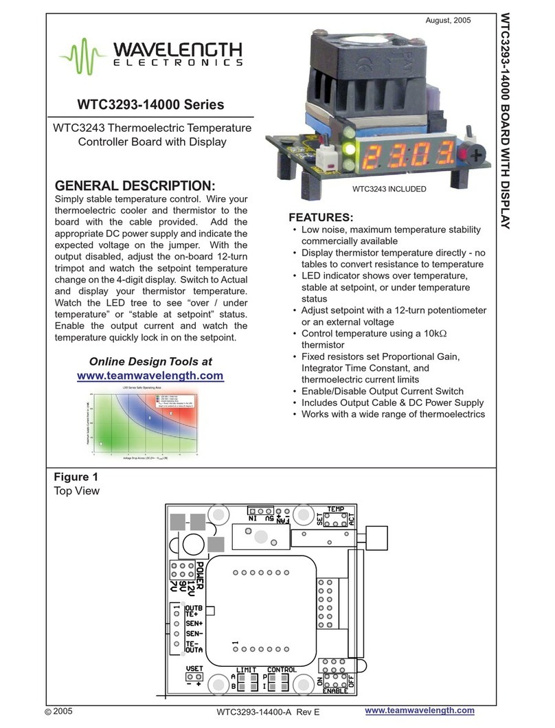
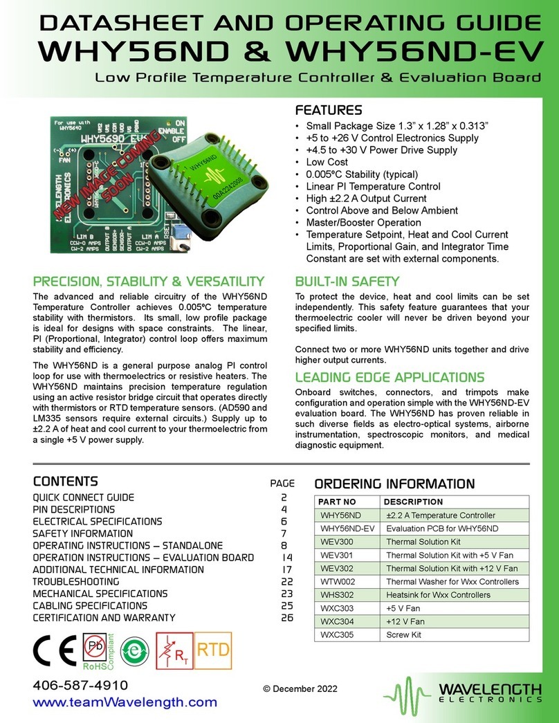
Wavelength Electronics WHY56ND User manual

Wavelength Electronics
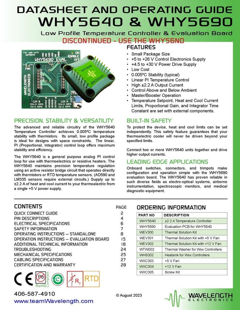
Wavelength Electronics WHY5640 User manual

Wavelength Electronics
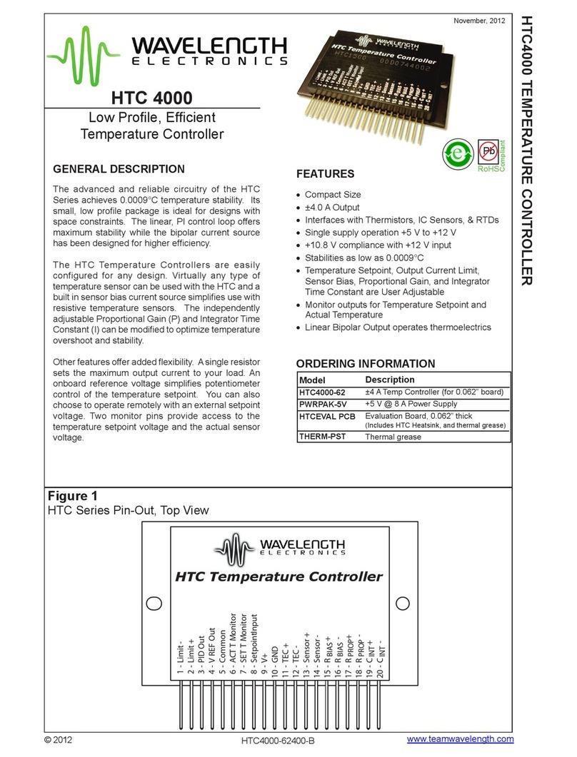
Wavelength Electronics HTC 4000 User manual

Wavelength Electronics
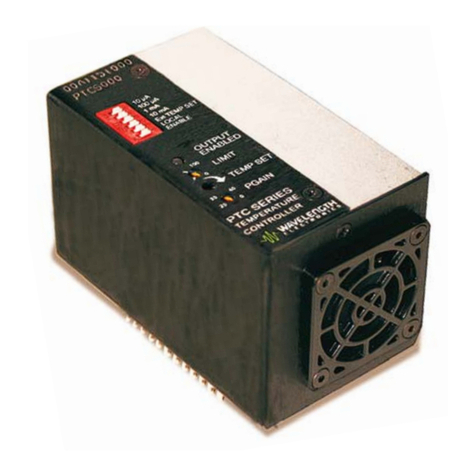
Wavelength Electronics PTC5000 User manual

Wavelength Electronics
Wavelength Electronics LDTC0520 User manual

Wavelength Electronics
Wavelength Electronics WTC3243 User manual