Bluesky AUDIO MANAGEMENT CONTROLLER User manual

AUDIO MANAGEMENT CONTROLLER (AMC) MANUAL
WINDOWS AND OS X VERSION 10.3
Page 1

DESCRIPTION
The Blue Sky Audio Management Controller (AMC) is an 8-channel audio DSP plat orm with both
24-bit digital and analog I/O.
Each channel o the AMC has a sample rate converter (by stereo pair), a 31 band 1/3 octave
equalizer, eight parametric / ree assignable ilters, individual channel delays, and lip-sync delay.
A 16x8 cross-point mixer allows any input to be mixed to any output.
The lexible bass management system can be customized on a channel-by-channel basis, or
turned-o completely.
The AMC has 6 presets, each o which stores complete setup in ormation, including ilter setting,
I/O con iguration, delays, etc.
The AMC includes control so tware that is a Windows and OS X application that connects through
the USB port.
The AMC includes SRO (Sound Room Optimization) so tware which includes an MLS based
measurement system with auto room correction or expert manual mode, correcting the in- room
speaker response to a user de inable target curve.
Requires irmware and so tware 5.13 or above.
Page 2

Table o Contents
DESCRIPTION...................................................................................................................................2
AMC FEATURES................................................................................................................................4
IMPORTANT SAFETY INSTRUCTIONS...........................................................................................5
AMC FRONT PANEL..........................................................................................................................7
AMC REAR PANEL............................................................................................................................7
1. POWER......................................................................................................................................7
2. CHANNEL ASSIGNMENTS.......................................................................................................7
3. ANALOG I/0...............................................................................................................................8
4. DIGITAL I/0.................................................................................................................................8
THE AMC REMOTE.........................................................................................................................11
FRONT PANEL.............................................................................................................................11
REAR PANEL...............................................................................................................................12
MENU ITEMS...............................................................................................................................13
QUICK SETUP AND USE................................................................................................................15
UPDATING THE FIRMWARE..........................................................................................................16
UPGRADING THE FIRMWARE IN THE AMC RACK.....................................................16
UPGRADING THE FIRMWARE IN THE AMC REMOTE..............................................................17
THE AMC CONTROL SOFTWARE.................................................................................................18
INSTALLING THE AMC CONTROL SOFTWARE IN WINDOWS...............................................18
INSTALLING THE AMC CONTROL SOFTWARE IN OS X.........................................................18
RUNNING THE PROGRAM........................................................................................................18
THE AMC CONTROL MAIN SCREEN.............................................................................................19
NAVIGATING AROUND THE INTERFACE.................................................................................19
CROSS MIXER................................................................................................................................22
BASS MANAGEMENT.....................................................................................................................23
1/3 OCTAVE EQ...........................................................................................................................25
UNASSIGNED CHANNEL FILTERS...........................................................................................25
TARGET CURVES...........................................................................................................................27
SPEAKER ROOM OPTIMIZATION (SRO)......................................................................................29
OVERVIEW..................................................................................................................................29
ADDITIONAL EQUIPMENT YOU WILL NEED............................................................................30
SETTING UP THE ART USB DUAL PRE in WINDOW...............................................................30
SETTING UP THE ART USB DUAL PRE IN OS X......................................................................31
GUIDELINES ON MICROPHONE SETUP..................................................................................32
USING THE SRO PROGRAM (SIMPLE SET UP)......................................................................33
STARTING THE SRO PROGRAM..............................................................................................34
FREQUENCY RESPONSE CURVE................................................................................................35
OPTIMIZING USING 1/3 OCTAVE FILTERS...................................................................................36
OPTIMIZING USING 8 UNASSIGNED FILTERS............................................................................36
CALIBRATING THE AMC TO DISPLAY dBSPL..............................................................................42
AMC SPECIFICATIONS...................................................................................................................43
Page 3

AMC FEATURES
o 8 balanced analog inputs and outputs with switchable +12 / +24 dBu maximum levels
o 8 AES 110 ohm digital inputs and outputs, each trans ormer Isolated
o Burr Brown / TI PCM1792A digital to analog converter with 132 dB SNR
o Burr Brown / TI PCM4222 analog to digital converter with 124 dB SNR.
o Cirrus Logic CS8422 sample rate converter with 140 dB SNR
o National LME49760 op amps, with 55 MHz bandwidth and 20V/us slew rate
o Analog / Digital I/O selectable in pairs.
o Simultaneous digital and analog outputs
o Adjustable analog and digital output o set
o 16 in x 8 out cross mixer
o Quad Analog Devices 56 bit ixed point processor
o Digital input sample rate range 44.1 kHz to 192 kHz.
o Internal sample rate 48 kHz or 96 kHz (switchable)
o 31 Band 1/3 octave double-precision digital EQ per channel
o 8 user de inable 2nd order double precision digital ilers per channel
o 6 user de ined presets
o 4 line large lighted high contrast display on remote
o Solo / Mute channel selection buttons.
o Mute, Dim, and Re gain buttons
o Adjustable channel and lip sync delays
o Adjustable channel calibration
o SRO room optimization so tware
o Firmware updatable through the USB port.
Page 4

IMPORTANT SAFETY INSTRUCTIONS
Page 5

1. Read Instructions.
2. Keep these Instructions.
3. Heed all Warnings.
4. Follow all Instructions.
5. Do not use near water.
6. Clean only with a dry cloth.
7. Do not install near any heat sources such as radiators, heat registers, stoves, or other
apparatus that produce heat.
8. Unplug this apparatus during lightning storms or when unused or long periods o time.
9. Re er all servicing to quali ied service personnel. Servicing is required when the apparatus
has been damaged in any way, such as a power-supply cord or plug is damaged, liquid has
been spilled or objects have allen into the apparatus, the apparatus has been exposed to rain
or moisture, does not operate normally, or has been dropped.
10. The system must be placed on a irm, level sur ace where it is not exposed to dripping or
splashing liquids.
11. Do not place lammable material above or beneath the AMC.
12. Be ore making connections to a Blue Sky AMC, ensure that the power is o and other
components are in mute or stand-by mode.
13. Make sure all cable terminations are o the highest quality, ree rom rayed ends, short
circuits, or cold solder joints. Be especially care ul when connecting to terminals marked which
may have hazardous voltages on them during operation.
14. Allow adequate ventilation or the rack.
15. THERE ARE NO USER SERVICEABLE PARTS INSIDE A BLUE SKY AMC
Page 6

AMC FRONT PANEL
POWER Switch – Turns AMC on and o .
USB 2.0 Connector – used or updating irmware in the AMC rack and the AMC Control program.
STATUS / POWER LED – Indicates the AMC is powered. When lashing indicates internal
microcontroller is operating normally.
AMC REAR PANEL
1.POWER
The AMC has switching power supplies that operates on 100-230 VAC 56/60 Hz. No voltage
change switch required. Standard IEC 3 pin power connector.
2.CHANNEL ASSIGNMENTS
The AMC I/O connections use DB25 connectors wired to the TASCAM/ Avid protocol or both
analog and digital. These DB25 cables are not supplied.
The channel assignments are SMPTE standard
1. Le t
2. Right
3. Center
Page 7

4. LFE
5. Le t Surround
6. Right Surround
7. Le t Rear
8. Right Rear
The channel assignments match the labels on the remote.
However, these channels labels are or re erence only. Any channel can be used or any purpose
desired. The only exception is the LFE channel which includes the bass management ilters. Since
these ilters can be disabled (using the AMC Control So tware), the LFE channel can be
recon igured as a standard channel like the others.
3.ANALOG I/0
The analog inputs and outputs are balanced with a switchable maximum level o +12/+24 dBu.
Both analog and digital outputs are active irrespective o whether the inputs are digital or analog.
4.DIGITAL I/0
The digital inputs and outputs are AES/ EBU 110 impedance trans ormer isolated I/O. The digital
inputs have built-in 140 dB dynamic range sample rate converters, which convert any digital input
to the native sample rate. The internal sample rate can be set as a global parameter to 48 kHz or
96kHz through the menu on the remote. Changing the sample rate will reset the rack unit and
restart at the new sample rate.
Page 8

EXTERNAL MUTE INPUT
The green barrier strip has an external mute input, which allows an external switch or 5 V trigger to
mute the entire system. This is normally used or talk-back muting.
The mute input is opto – isolated to prevent ground loops when using an external supply. To use a
switch, connect the normally open switch across pins 1 and 4 and connect a jumper wire between
pin 4 and pin 5 n 3. Close the switch to mute the AMC and open it to unmute the AMC.
To use an external +5 V trigger to mute the rack, connect the voltage across pin 4 and pin 5. A +5
V signal will now mute the rack
REMOTE CABLE
The cable between the remote and the rack unit is a standard Ethernet Cat-5/6 UTP cable with
RJ–45 connectors.
However the signal protocol between the remote and rack is RS-232 not Ethernet.
The remote cable has been tested to 50 t.
Warning: Do not plug the remote or rack unit into an Ethernet port. It was not designed or this,
and doing so may damage the port or unit.
Page 9

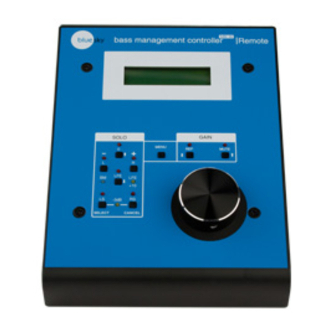
THE AMC REMOTE
FRONT PANEL
GAIN – changes the system gain in 1.0 dB increments . Also used to scroll through the menus and
change parameters.
MUTE – mutes all channels, both digital and analog
REF – sets the system gain to a user de ined re erence level. The de ault setting is -20 dB. The
de ault setting can be changed utilizing the remote menu or the AMC Control So tware.
Page 10

DIM/CANCEL – reduces the current system gain by the DIM value. The de ault setting is -10 dB.
The de ault setting can be changed utilizing the menu or the AMC Control So tware. The
DIM/CANCEL switch is also used to exit the menu mode
MUTE MODE – the Solo/ Mute channel buttons operate in mute mode. Switching between Solo
and Mute modes clears all solo/mute buttons
SOLO MODE – the Solo/ Mute channel buttons operate in a Solo Mode. Switching between Solo
and Mute modes clears all solo/mute buttons.
SOLO/MUTE – Solo’s or Mutes that channel. Solo buttons can now be pressed in unison. For
example i you want to solo L, C, R. so can press those buttons all at once.
PRESETS – loads the preset.
MENU – allows a limited number o parameters to be changed on a preset. When exiting the
menu mode, the changed parameters are automatically stored in lash memory.
REMOTE MENU LOCKOUT- Access to the ull menu can be restricted by requiring the user to
enter a 4 digital access code. I this eature is activated, whenever the menu button is pressed, the
user will have to use the preset buttons to input the correct 4 digital code to access the ull menu.
A limited user menu can be access by hitting the menu button again. This eature can be turned on
or o and the access code changed using the AMC control so tware remote code.
REAR PANEL
USB 2.0 CONNECTOR - used or irmware updates to the remote
REMOTE MAIN RS232 - Connects the Remote to the AMC rack
Page 11

REMOTE AUX RS232 - Connects the remote to a 2nd AMC rack or 16 channel operation
THE MENU
Menu Switch – enters the menu mode and switches between scroll and parameter modes.
In the Scroll mode, the gain control “scrolls” through the menu items.
In the Parameter mode, the gain control changes the selected parameter. To switch between
modes, tap the menu key. The current mode is displayed at the bottom o the display.
Dim/Cancel switch - exits the menu mode and stores the changed values in the current preset.
Preset Buttons – when the remote lock out is on, used to input access code.
An example o using the MENU to change the le t calibration to +3 dB.
1. Tap the menu switch.
2. Rotate the gain control to cycle through the menu items to le t calibration.
3. Tap the menu switch to enter parameter mode.
4. Rotate the gain control CW or CCW until the display reads +3.0 dB.
5. Tap the menu key to go back to scroll mode.
6. Tap the dim/cancel switch to exit the menu and store the preset.
7. To change multiple items, ollow 1-5 on each parameter and then hit the dim / cancel key
when you have completed all your changes.
MENU ITEMS
1. Channel Calibration – sets the output gain o set or the selected channel. Used to balance
channel levels.
2. Channel Delay – sets the time delay or the selected channel. Channel delay is used to
time align each speaker to compensate or the unequal distances between the listener and
the speaker. For example, a subwoo er is usually arther away rom the listener than the
ront speakers, so the sound rom the subwoo er arrives later than the sound rom the ront
speakers. In this case you would add additional time delay to each o the ront speakers to
time align with the subwoo er. The time delays o each speaker can be measured using the
Page 12

AMC Control so tware and the optional recommended measurement microphone and USB
audio inter ace. (See the section on additional equipment you will need, below.)
3. Lip Sync delay – Many video displays have video processing delays which can cause the
audio to be out o sync with the picture. To compensate or video delay, an overall audio
time delay can be added to re-synchronize the audio with the picture.
4. Re Gain – sets the system gain when Re button is pressed
5. Dim Gain – sets the gain reduction when the DIM button is pressed
6. +12/+24 analog max level switch – Some studio monitors are high gain devices that have
a nominal input level o around -10 dBu, and not +4 dBu. This switches the gain structure to
+12 dB to optimize the signal to noise ratio. Only a ects the analog inputs and outputs.
When using digital IN and analog OUT, this parameter a ects the maximum output level o
the analog output.
7. Channel pink noise – Generates a low level pink noise signal on the digital and analog
outputs o the selected channel; The pink noise signal is mainly used to trace down output
channel wiring or to veri y the AMC is outputting a signal.
8. Restore to actory de aults - clears all entered preset data and restores the actory de ault
presets, which include the de ault target curve setup. Follow the prompts on the screen.
9. System rate rate – selects either 48 or 96khz as the system sample rate. Changing the
sample rate will reset the system, so it is recommended that the user exit the AMC control
so tware, because a reset will interrupt the USB connection.
10.Digital input Lock Status – indicates that the digital input is locked to a valid digital stream
11. Bass Management ON/OFF- I bass management is turn o , all crossovers are disable
except or the LFE ilter.
12.SPL Display O set Adjustment – adjust the measured dBSPL to the current system
gain. The de ault is -20 dB = 85 dBSPL. See Calibrating the System to Display dBSPL or
more in ormation.
13.Display dBSPL On/O – turns dBSPL display on or o .
14.EQ Filter Bypass - When On bypasses all systems EQ including graphic equalizer and
ree ilters. Does not a ect actual EQ values.
USER MENU ITEMS - When the remote is locked, the user has access to REF gain, DIM gain,
PINK noise, the digital input status screen, Bass Management On/O , and EQ Bypass.
Page 13

QUICK SETUP AND USE
The AMC comes with six de ault which are a mix o digital and analog.
Any preset can be recon igured to analog or digital or a mix
The display has a short description o the presets. These presets can be modi ied on a limited
basis using the menu on the remote or completely recon igured using the AMC Control So tware.
1. Connect Audio I/O cables to the AMC and your speaker system.
2. Connect AMC Remote to AMC Rack using supplied Cat 5/6 cable.
3. Connect power cable to AMC Rack.
4. Turn on Rack AC power switch.
5. Wait until ront panel LED is lashing and remote mutes.
6. Power-up your speakers.
7. Hit mute button to cancel mute.
8. Enter menu and scroll to Pink Noise.
9. Hit Menu button to switch to parameter mode.
10.Scroll through pink noise channels to veri y audio is coming rom correct speakers.
Note: The level will be low.
11. Hit Menu to return to Menu scroll mode.
12. Hit Dim/Cancel to return to normal operation.
Page 14

UPDATING THE FIRMWARE
DIFFERENCES BETWEEN UPDATING IN WINDOWS AND OS X
The only di erences between updating using Windows or OS X is that with Windows you are
required to use an installer to install the irmware updater on your computer. With OS X , the
installers are apps that are sel contained.
The irmware in both the remote and rack can be updated through the USB ports and the using the
Blue Sky Firmware Tool. There are separate updateras or the Remote and Rack.
UPGRADING THE FIRMWARE IN THE AMC RACK
NOTE: Di erent versions o the AMC control so tware require irmware version numbers matching
the AMC control so tware. For example, AMC control irmware 5.05 requires irmware version 5.05
be installed in the remote and rack. Letter versions modi ier, like 5.05 B, will all work with AMC
Control so tware o the same base number.
Note: The irmware can only be updated when the rack is powered down.
1. Install the Blue Sky AMC RACK Firmware X.XX update tool. The
installation tool will create a Blue Sky in the Program Files (0x86) sub-directory and
install the update program and the new hex ile in that directory.
2. I you get a message that the program requires Elevation and will not run, right click on
the installer and click Run As Administrator.
3. Power down the AMC RACK and plug-in the USB cable. I this is irst time you've
connected the AMC Rack to your computer you may get a message that the computer
is installing drivers or the USB inter ace. Wait until that completes and the ront panel
LED lashes a couple o times a second.
4. Start the program and the dialog box will show
BLUE SKY
AMC RACK BOOTLOADER REV 1.00
and the currently installed irmware.
5. I the dialog windows says
BLUE SKY
AMC RACK REV x.xx
Application unable to communicate with the device
Power o the unit, disconnect the USB cable, and plug the cable back in and restart
the program.
Page 15

6. Hit the UPDATE FIRMWARE BUTTON
7. The updater will update the irmware and read the new irmware version.
8. Close the program, disconnect the USB cable and you are done
UPGRADING THE FIRMWARE IN THE AMC REMOTE
Note: The irmware can only be updated when the remote is disconnected rom the rack or the
rack is powered- down..
1. Install the Blue Sky AMC Remote Firmware X.XX update tool. The
installation tool will create a Blue Sky in the Program Files (0x86) sub-directory and
install the update program and the new hex ile in that directory.
2. I you get a message that the program requires Elevation and will not run, right click on the
installer and click Run As Administrator.
3. Disconnect AMC Remote and plug-in the USB cable. I this is irst time you've
connected the AMC Remote to your computer you may get a message that the
computer is installing drivers or the USB inter ace.
4. Start the program and the dialog box will show
BLUE SKY
AMC Remote BOOTLOADER REV 1.00
and the currently installed irmware.
5. I the dialog windows says
BLUE SKY
AMC Remote REV x.xx
Application unable to communicate with the device
Power o the unit, disconnect the USB cable, and plug the cable back in and restart
the program.
6. Hit the UPDATE FIRMWARE BUTTON
7. The updater will update the irmware and read the new irmware version.
Close the program, disconnect the USB cable and you are done
Page 16

THE AMC CONTROL SOFTWARE
The AMC Control So tware is available in two versions One is 32 bit Windows program that will run
on both 32 and 64 bit versions o Windows 7, 8, and 10. The second is a OS X version that will
run on Yosemite, EL Captain, and High Sierra. This program and is intended or use only with the
Blue Sky AMC and will not run without the AMC is connected to the computer by USB.
Both versions o the AMC Control so tware are available or download. Contact Blue Sky or a
download link.
INSTALLING THE AMC CONTROL SOFTWARE IN WINDOWS
Download the setup program and save it to your computer at a location where you can ind it.
Double-click o the setup program to install it. The installer will create a older under the program
iles (0x86) called Blue Sky and install the program in that older.
INSTALLING THE AMC CONTROL SOFTWARE IN OS X
Download the zip ile and unzip it to your desktop or application older.
RUNNING THE PROGRAM
Turn on the AMC and wait unit the red LED on the ront o the AMC is lashing approximately once
every two seconds and the remote mute button is lit..
Plug the USB cable into the ront o the AMC. I this is the 1st time you have connected the AMC to
your computer you may see a message that says USB detected, installing so tware. Wait till the
computer is done and the LED on the ront o the AMC goes back to lashing.
I everything is connected you should see the Main Screen:
Page 17

THE AMC CONTROL MAIN SCREEN
When using the USB inter ace, the AMC rack and the so tware are linked so preset changes and
parameter changes made on the remote or by the AMC program show on both. The remote update
may lag behind the so tware by a couple o seconds.
NAVIGATING AROUND THE INTERFACE
The blue boxes represent items that are activated when clicked with your mouse. In some cases
clicking a blue box will initiate an action. In other cases the box will open up another screen.
The black boxes with white text represent parameters that can be entered directly using the delete
key, the backspace key, numerical keypad and the enter key.
The check boxes (square) or radio button ( round) represent an either/or setting. For example, i
you click the +12dBu Max, the +24dBu Max button is turned o
Master Gain - displays the current master gain o the AMC. This value is automatically updated i
the gain control is moved, or i re erence and/or dim gain are selected.
dBSPL – displays and edits current dBSPL at current Master Gain setting. This values tracks the
Master Gain setting. This value is stored with each preset so when a single AMC is used with
multiple speaker setup, each setup can have it own re erence. I the DISPLAY dBSPL box is not
checked, this box is not visible.
Page 18

DISPLAY dBSPL – turn the dBSPL display on and o .
Re erence Gain- displays the current re erence gain setting. The re erence gain or this preset can
be modi ied directly by typing in the new value in the box. This value will also be updated i the
re erence gain setting is changed through the remote
Dim Gain- displays the current dim gain setting. The dim gain setting or this present can be
modi ied directly by typing in value in this box. This value will also be updated i the dim gain
setting is changed through the remote
System Sample Rate- shows the current internal sample rate o the AMC. This value can only be
changed through the remote.
Loading a preset – loads a preset Click on the blue buttons in the upper le t hand corner o the
Presets can also be loaded by hitting a button on the remote, which will be indicated on the AMC
screen.
Saving a preset – saves the currently loaded preset to the AMC rack. A loaded preset can be
saved to itsel or to any other preset location.
Preset display – these 3 lines o text are what will appears on the remote when a preset is loaded.
Each line o text can be changed directly using the keyboard.
Remote Access Code - a 4 digit access code or the remote menu . Since the preset buttons are
used to enter the code, only digits 1 to 6 are allowed.
Restrict Remote Menu Enable- when checked requires the user to enter the correct 4 digit code
to access the ull Remote Menu.
SRO- opens up the speaker room optimization panel.
Save Presets to File- pressing this button will open up a dialogue to save all presets to a text ile.
The text ile is in a human readable orm and has all the parameters the makeup the preset.
Load Presets From File-loads a previously saved preset ile.
Analog +12dB/ +24 dB Max switch – Switch the analog IO between +12 and +24 dB maximum
output level.
Digital in lock status box – shows whether a digital input has a valid digital signal attached.
16 In 8 Out Mixer- opens up the cross mixer panel (see CROSS MIXER )
Base Management- opens up the base management panel ( see Base Management)
EQ buttons- opens up the channel equalizers(see EQ).
Channel Calibration – sets the relative balance between the channels. These values can be
Page 19

entered directly in the boxes or entered automatically using the SRO procedure. See the Speaker
Room Optimization (SRO) section below or more in ormation.
Channel delay in milliseconds - sets the individual time delay or each channel output and is
used to time align the speakers.
Lip sync delay in milliseconds- set some master time delay or all channels both digital and
analog and is used mainly match audio to picture .
Analog gain dB - master o set or the analog outputs and is normally used when operating with
digital in and analog out.
Digital gain dB - master o set o the digital outputs and is normally used when operating analog
in to digital out
Grey preset setup buttons- the buttons along the bottom o the screen, set up the loaded preset
to a common set up values.
Page 20
Table of contents
Other Bluesky Controllers manuals