© 2019 www.teamWavelength.com 9
QCL OEM SERIES LOW-NOISE DRIVER
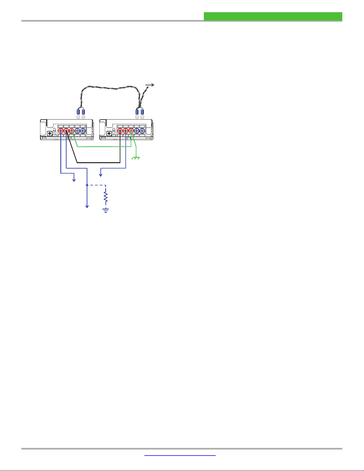
WIRE THE POWER SUPPLIES
Wire the QCL driver to the dual power supplies as shown in
Figure 4. If you are using the PWRPAK-24V power supplies
kits WCB312 and WCB313.
AC(L) AC(N)FG-V+V AC(L) AC(N)FG-V+V
Y NEGATIVE SUPPLY
V- (Pin J4-2)
V+ (Pin J4-3)
Ground
(Pin J4-1)
Ground Interconnect
Neg-to-Pos Interconnect
Ground Wire
Twisted Pair
Chassis
Ground
150kΩ
Earth
Ground
1
1
11
2
2
2
1. Cable included as part of the WCB312 Power Supply Wiring Kit
2. Included with the QCL Driver.
Connect to AC Mains; refer to power supply
specifications for input voltage requirements.
Figure 4. QCL Power Supply Wiring
Follow these instructions to wire the power supplies using
the WCB312 and WCB313. The same method applies to
connect other power supplies to the QCL driver.
•
as shown in Figure 4.
•
terminals on the power supplies.
•
bench).
•
and V+ of Negative Supply.
• Use the remaining ring lugs to connect the power
V– terminals of the power supplies. See page 20 for
information on the WCB313 cable.
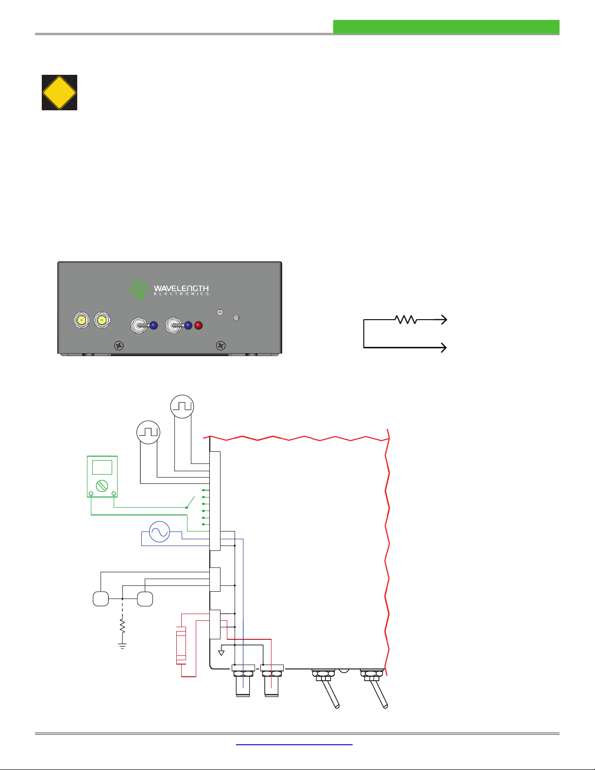
Figure 4
electronics ground is tied to earth ground at some point
USB cable connection.
This resistor provides a lossy connection from system
Some systems can have problematic ground loops. If this
POWER and ENABLE lines. It is not a requirement for low
Table 4 for
the remote Switch Settings.)
NOTE: For remote operation the front panel Power and
Enable switches must be on.
If you are unsure whether to include this resistor in your
assistance.
CONNECT THE TEST LOAD
test load rather than the actual quantum cascade laser.
Refer to page 2
instructions. Connect the test load now.
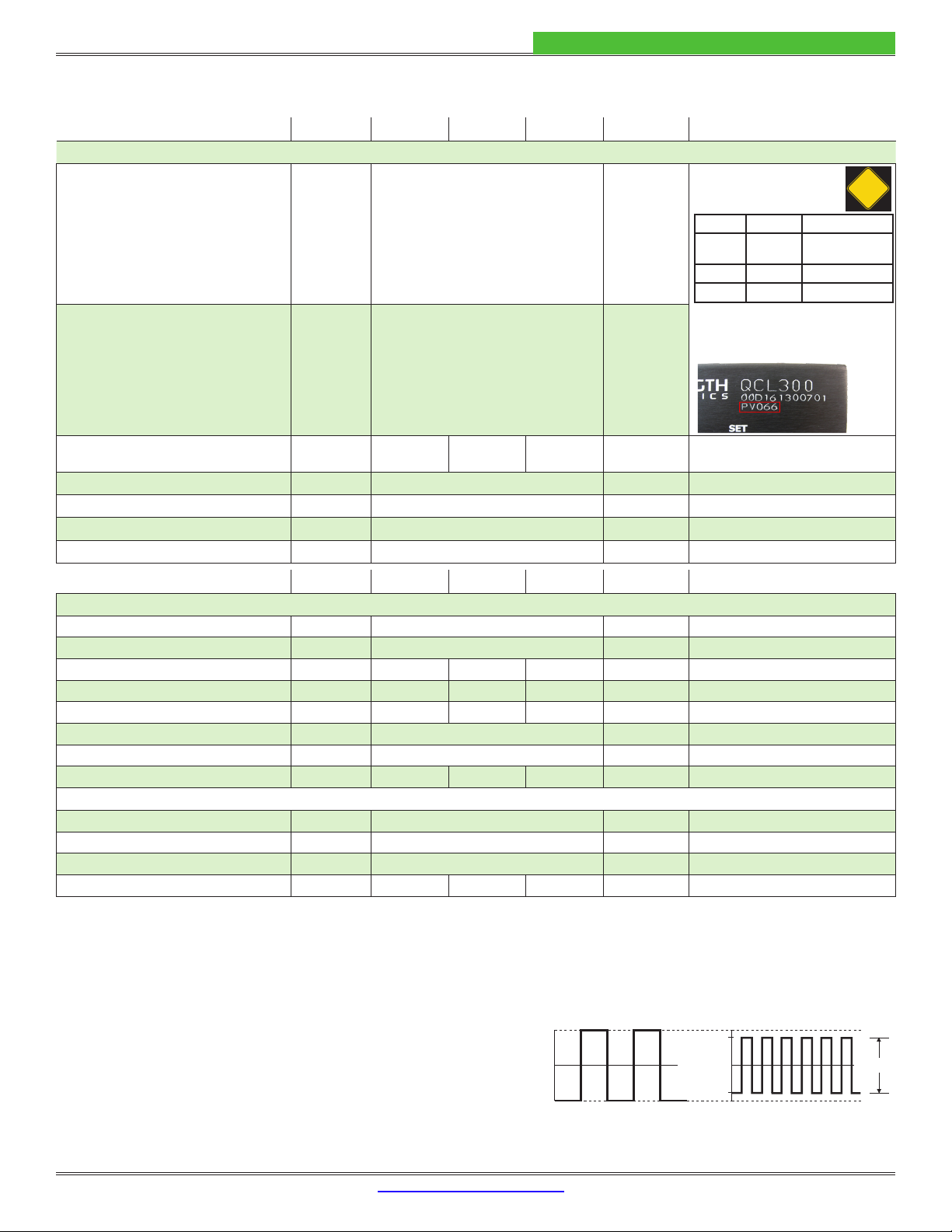
SET THE CURRENT LIMIT
The QCL driver employs a soft-clamping current limit. The
limit circuit begins to act at a current below the absolute
exceeding the absolute limit setpoint.
We recommend that setpoint is below 85% of the
current limit, because the noise level introduced into
the QCL rises when operating close to the current limit.
and 12 turns for the LIMIT trimpot.
blue POWER LED on the front panel will illuminate. Do not
enable the output at this time.
The current limit is set using the LIMIT trimpot on the front
•
referencing Table 3
VI_LIM_MON = ILIMIT / Transfer Function