www.teamWavelength.com
© 2010
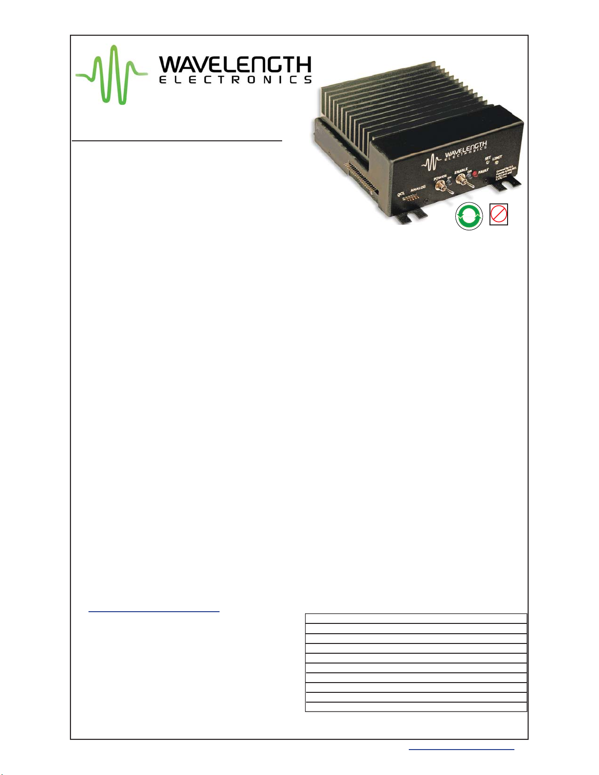
QCL500, QCL1000, QCL1500 Low Noise Quantum Cascade Laser Drivers
PAGE 1
QCL1500-00400-D
GENERAL DESCRIPTION:
The QCL1500 includes patented circuitry1ideal
for driving Quantum Cascade Lasers (QCLs)
where electronic noise, coupled through the
laser, can affect measurements.
This is an OEM controller, designed to be
integrated into field deployed systems or used
on a benchtop. It operates from dual DC power
supplies. Low noise can be achieved even with
certain switching power supplies.
An onboard Current Setpoint trimpot allows a DC
biastobeset. ItssignalsumswitharemoteAnalog
Input signal that can be negative or positive.
Safety: An onboard trimpot sets the current limit
as you monitor the setting - without driving current
through the QCL. Brownout, reverse voltage,
and overvoltage protection isolates the QCL from
power supply failures. An Overtemp Fault signal
minimizes the chance of failure due to overheated
electronics. An onboard Enable Switch controls
when current can flow to the QCL. A remote
Enable signal can also be used.
Applications: High performance chemical
sensing in biomedical, imaging, spectroscopy,
remote sensing, military, communications,
aerospace and materials processing industries.
To optimizenoise performance inyour application,
current range can be adjusted. Other product
variations are available. Please contact the
factory with your requirements at 406-587-4910
1Covered by U.S. Patents 6,696,887; 6,867,644 and
7,176,755. Licensed from Battelle Memorial Institute.
Minimize spectral drift, center wavelength jitter,
and linewidth
FEATURES:
• Off the shelf models at 500 mA, 1A, 1.5 A
• Can be delivered in other current ranges up to 2A
- with noise minimized for your QCL
• Compliance voltage up to 16 V
• Low noise: < 1A RMS over 100 kHz bandwidth
(graphs on page 5)
• Analog Input Setpoint sums with onboard trimpot
• Safety: Current Limit, 1.25 second ON delay with
100 msec current ramp, Remote Enable signal,
brown out, reverse & over voltage, overtemp
protection circuits
• Remote Power On and Enable signals are TTL
compatible and fully isolated
• Adjustable Current Limit with monitor
• Local power & enable / disable switches
• Protection relay shorts output when current is
disabled
• Shielded from external interference
• Constant Current Mode operation
• 3 dB bandwidth 2 -3 MHz
• Status Outputs can drive LEDs
• Small Package 6.55 x 5.5 x 2.3”
• Compatible with P/N PTCxxK-CH precision
temperature controllers
• Accessories include cables and power supplies to
simplify integration.
November, 2010
Low Noise QCL Driver
Pb
RoHS
Com
liant
Ordering Information
QCL500
QCL1000
QCL1500
QCL2000
QCL-SMA-ADAPT
WCB310
WCB311
WCB312
PWRPAK-24V
NOISE SCAN
500 mA Low Noise QCL Driver
1 A Low Noise QCL Driver
1.5 A Low Noise QCL Driver
Product Variations are available up to 2 A
Convert signal pins to SMA connectors
Low Noise Cable: SMA to SMA
QCL 20 pin connector with cables
QCL Dual Power Supply wiring kit
24 VDC Switching Power Supply
Noise Characterization Scan
e