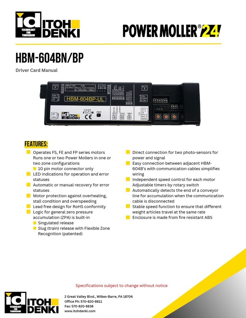
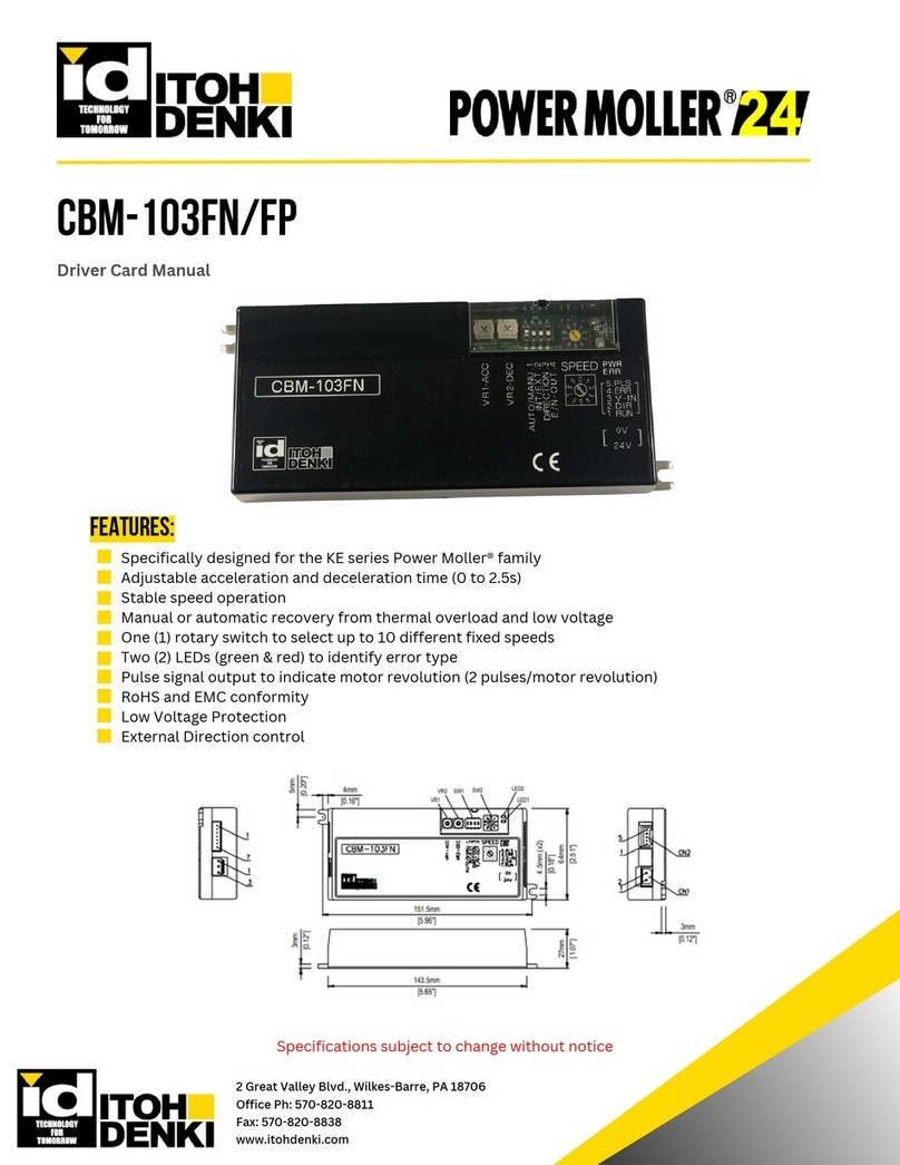
ITOH DENKI PM 500 FS User manual

1
CONDITIONS D’USAGE CONDITIONS OF USE
EINSATZBEDINGUNGEN CONDICIONES DE USO
Document non contractuel. Nous nous réservons le droit à tout moment de lui apporter toutes modi cations que nous jugerons utiles.
© ITOH DENKI
U1.2
EMC Directive
2006/42/CE
(1) Nouvelle désignation New designation
Neue Bezeichnung Nueva designación
(2) Ancienne désignation Old designation
Alte Bezeichnung Antigua designación
brushless
(1) (2)
PM 500 FS 50
PM 500 FS-B 50B
PM 500 FP 50P
PM 500 FE 50E
PM 500 FE-B 50EB
PM 500 XE
50XE
PM 500 XP
50XP
(1) (2)
PM 605 FE 60E
PM 605 FE-B 60EB
PM 605 XE 60
XE
PM 605 XP 60
XP
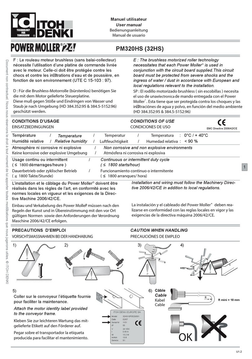
• Température : 0°C / + 40°C
•Humidité relative sans condensation < 90 %
• Atmosphère ni corrosive ni explosive
• Vibration 0,5 G maxi
• Usage continu ou intermittent
(voir spéci cations techniques)
• L’installation et le câblage du Power Mol-
ler®doivent être réalisés dans les règles
de l’art, en conformité avec les normes
locales en vigueur et les exigences de la
Directive Machine 2006/42/CE.
• Temperature : 0°C / + 40°C
•Relative humidity no condensation < 90 %
• Non corrosive and non explosive environ-
ments
• Vibration 0,5 G maxi
• Continuous or intermittent duty cycle
(See technical speci cations)
• Installation and wiring must follow the
Machinery Directive 2006/42/CE in addi-
tion to local regulations.
• Temperatur : 0°C / + 40°C
• Luftfeuchtigkeit keine Kondensation < 90 %
• Keine korrosive oder explosive Umgebung
• Vibration 0,5 G maxi
• Dauerbetrieb oder zyklischer Betrieb
(sh.technische Spezi kationen)
• Einbau und Verkabelung des Power Moller®
müssen nach den Regeln der Kunst und in
Übereinstimmung mit den vor Ort gültigen
Normen sowie den Anforderungen der Ver-
ordnung Maschine 2006/42/CE erfolgen.
Temperatura : 0°C / + 40°C
• Humedad relativa sin condensación < 90 %
• Atmósfera ni corrosiva ni explosiva
• Vibración 0,5 G maxi
• Funcionamiento continuo o intermitente
(ver especi caciónes tecnicas)
• La instalación y el cableado del Power Mol-
ler® deben realizarse en conformidad con
las reglas locales en vigor y las exigencias de
la directiva máquina 2006/42/CE.
1Référence produit Product reference
Artikelbezeichnung Referencia producto
2
Mois et année de
fabrication
Month and year of
manufacturing
Fertigungsmonat und
-jahr
Mes y año de fabrica-
ción
3Numéro de série Serial number
Seriennummer Número de serie
4Indice de protection Protection index
Schutzart Índice de protección
5
Alimentation électrique
Supply voltage
Stromversorgung Alimentación eléctrica
8Vitesse Speed
Geschwindigkeit Velocidad
9Fonctionnement Function
Betrieb Funcionamiento
1
2
3
4
5
8
9
PM 500 XK
PM 500 XC
Manuel utilisateur
Bedienungsanleitung
User manual
Manual de usuario

2
Obligatoire Obligatory
Zwingend
L
A = L + 10 mm
B = L + 13 mm
Obligatoire Obligatory
Zwingend
Ref : A-081-GRef : A-071-G Ref : A-081-GRef : A-071-G
Non contractual document. We reserve the right to introduce modi cations that we consider useful, at any time. © ITOH DENKI
R
OK
R mini = 18 mm
PRECAUTIONS D’EMPLOI CAUTION WHEN HANDLING
VORSICHTSMASSNAHMEN BEI DER HANDHABUNG
PRECAUCIÓNES DE EMPLEO
MONTAGE DU POWER MOLLER®MOUNTING THE POWER MOLLER ®
MONTAGE POWER MOLLER®MONTAGE DEL POWER MOLLER ®
PM 500 FS (50) - PM 500 FS-B (50B) - PM 500 FP (50P)
PM 500 FS (50) - PM 500 FS-B (50B)
OK
M12 P1,25M12 P1,25
Obligatoire Obligatory
Zwingend L
B = L + 14 mm
Obligatoire Obligatory
Zwingend
Ref : P-0B1 Ref : P-0C1 Ref : P-0B1 Ref : P-0C1
U1.2

3
PM 500 FE (50E) - PM 500 FE-B (50EB) - PM 500 XE (50XE) - PM 500 XP (50XP) - PM500XC - PM500XK
PM 605 FE (60E) - PM 605 FE-B (60EB) - PM 605 XE (60XE) - PM 605 XP (60XP)
M12 P1,25
En option Optional
Wahlweise Opción L
A = L + 10 mm
B = L + 13 mm
Obligatoire Obligatory
Zwingend Obligatorio
Ref : A-081-GRef : A-071-G
Ref : P-0B1 Ref : P-0C1
M12 P1,25
Obligatoire Obligatory
Zwingend Obligatorio L
A = L + 15 mm
B = L + 15 mm
Obligatoire Obligatory
Zwingend Obligatorio
M8 X 14
Ref : P-0B1 Ref : P-0C1
En option Optional
Wahlweise Opción
L
A = L + 10 mm
B = L + 13 mm
Obligatoire Obligatory
Zwingend Obligatorio
Ref : A-081-GRef : A-071-G Ref : A-081-GRef : A-071-G
Obligatoire Obligatory
Zwingend Obligatorio
L
A = L + 15 mm
B = L + 15 mm
Obligatoire Obligatory
Zwingend Obligatorio
M8 X 14
Ref : A-081-GRef : A-071-G
U1.2

4
1. Préparer le châssis du convoyeur pour
le montage des rouleaux et des plaques de
xation du Power Moller®.
1. Bereiten Sie den Förderrahmen zum Einbau
der Rollen und der Drehmomentstützen des
Power Moller®vor.
1. The conveyor frame should be drilled
or punched to accommodate the 11,1 mm
hexagonal shaft and drilled with 2 holes to t
the locking brackets.
1. Preparar el chasis del transportador para
el montage de los rodillos y de los soportes de
jación del Power Moller®.
12 mm
mini
Hexa : 11,2 mm Ø 12,1 mm
34
45
= =
Ø 5,3
60
34
Ø 5,3
46
1,5
2,9
9
16
M5
Ø 8
51
45
Ref : A-071-G Ref : A-081-G
Hexa : 11,2 mm
12 mm
mini
Ø 12,1 mm
Ø 8,4 mm
Côté axe libre
Idle end cap side
Seitenkappe eje lado tapa
33
40
49
Ø12.8
10
22
1.5
311.1
33
40
49
Ø12.8
10
22
1.5
11.1
3
18,75
21,5
6,82
Ref : P-0B1 Ref : P-0C1
M8 x 14
U1.2

5
3. Introduire l’axe du côté câble, puis l’axe
rétractable opposé à l’aide d’un tournevis ou
d’une simple pression du doigt.
Attention : Prévenir tout risque de
cisaillement du câble.
3. Setzen Sie die Achse auf der Kabelseite und
anschließend mit Hilfe eines Schraubenziehers
oder einfach mit Fingerdruck die Federachse ein.
Achtung : Beugen Sie der Gefahr von Kabel-
bruch vor .
3. Then insert the motor output shaft followed
by the spring-loaded shaft using a screw-dri-
ver or by simply pushing the end of the shaft.
Caution : Prevent risk of shearing the
cable.
2. Monter les Power Moller®équipés de
leurs courroies : en ler le câble sans
l’endommager dans le trou du châssis.
2. Einbau des Power Moller®: Führen Sie das
Kabel durch die Bohrung im Seitenpro l, ohne
es zu beschädigen.
2. Mount the Power Moller®in the frame by
rstly inserting the supply cable through the
frame hole taking care not to damage it.
2. Montar los Power Moller®equipados de
sus correas: pasar el cable en el agujero
correspondente, teniendo cuidado de no dañarlo.
3. Introducir el eje del lado cable y el eje con
muelle con la ayuda de un destorrnillador o de
una simple pressión del dedo.
Cuidado: Prevenir todo riesgo de cizalladura
del cable.
U1.2

6
C =
30 Nm ±10%
4. Serrer l’écrou M12 pour bloquer l’axe
moteur du Power Moller®.
4. Ziehen Sie die M12 Schraubefest, umdie Moto-
rachse des Power Moller®zu blockieren.
4. The Power Moller® shaft is secure by
accurately tightening the M12 nut.
4. Apretar la tuerca M12 para bloquear el eje
motor del Power Moller®.
4. Ajuster la plaque de xation, puis serrer
les écrous M5 pour bloquer l’axes du Power
Moller®.
4. Richten Sie die Drehmomentstütze aus, und
ziehen Sie die M5 Schrauben fest, um die Moto-
rachse des Power Moller®zu blockieren.
4. Adjust the motor bracket, secure the
Power Moller®shaft by accurately tightening
the M5 nut.
4. Ajustar los soportes de jación y mantener
apretadas las tuercas M5 para bloquear el eje
motor del Power Moller®.
M5
C = 6 Nm ±10%
Plaque ref. P-0B1 ou ref. P-0C1 Plate ref. P-0B1 or P-0C1
Halterungsplatte Ref.P-0B1 oder P-0C1 Placa ref. P-0B1 o ref. P-0C1
Plaque ref. A-071-G ou ref. A-081-G Bracket ref. A-071-G or A-081-G
Halterungsplatte Ref.A-071-G oder A-081-G Placa ref. A-071-G o ref. A-081-G
M12 P1,25 M12 P1,25
Ref : P-0B1 Ref : P-0C1
19
8
Ref : A-081-GRef : A-071-G
U1.2

7
Axe taraudé pour vis M8 Female threaded M8 shaft.
Achse mit Innengewinde für eine M8-Schraube Eje con rosca interior M8
5. Bloquer l’axe côté intérieur du convoyeur
avec une clé de 13 et visser la vis M8, équi-
pée de sa rondelle, avec une clé Allen de 6
pour bloquer l’axe du Power Moller®.
5. Die Achse vomInneren des Förderers mit einem
13er Schlüssel blockieren und die M8-Schraube samt
Scheibe mit dem 6er Innensechskantschrauber von
aussen anschrauben, umdie Achse vom Power Moller®
zu blockieren.
5. Lock the shaft inside the conveyor with a 13mm
spanner and screw the M8 bolt and washer into
the Power Moller®shaft with a 6mm allen key.
5. Bloquear el eje en el lado interior del chasis
con una llave de 13 y apretar el tornillo M8,
equipado de su arandela, con una llave Allen de 6
para bloquear el eje del Power Moller®.
6
C = 30 Nm ±10%
13
M8 X 14
6. Véri er l’écart entre le convoyeur et le
Power Moller®: voir pages 2 et 3.
7. Monter les rouleaux libres et véri er
leur alignement, notamment les positions
des gorges et dents de poulies pour les
courroies striées.
6. Prüfen Sie den Abstand zwischen dem
Seitenpro l und dem Power Moller
®: sh.Seite 2
und 3.
7. Bauen Sie die Tragrollen ein, und überprüfen
Sie die Ausrichtung, besonders die Stelle von
den Sicken und von den Antriebszähnen für die
Keilriemen.
6. Check that the clearance between the
frame and the endcap of the Power Moller®:
See pages 2 and 3.
7. Assemble the slave rollers and check their
alignment, note the position of the pulley
grooves and teeth for V-rib belts.
6. Asegurarse que el juego entre los hierros del
transportador y el Power Moller®: ver páginas
2 y 3.
7. Montar los rodillos libres y veri car la
alineación, particularmente las posiciones de las
gargantas y de los dientes de poleas para correas
estriadas.
U1.2

8
MONTAGE AVEC MANCHONS CONIQUES INSTALLATIONWITH TAPERED SECTIONS.
AUFBAU MIT KONISCHENAUFSCHIEBLINGEN
MONTAJE CON MANGUITOS CONICOS
Supports verticaux Vertical frames
Senkrechte Stütze Soportes verticales
Supports inclinés Inclined frames
Schräge Stütze Soportes inclinados
Obligatoire Obligatory
Zwingend
Obligatoire Obligatory
Zwingend
Ref : A-081-GRef : A-071-G Ref : A-081-GRef : A-071-G
Ref : P-0B1 Ref : P-0C1 Ref : P-0B1 Ref : P-0C1
M8 X 14
M12 P1,25 M12 P1,25
Obligatoire Obligatory
Zwingend
Obligatoire Obligatory
Zwingend
Ref : P-0B1 Ref : P-0C1 Ref : P-0B1 Ref : P-0C1
M8 X 14
Ref : A-081-GRef : A-071-G
U1.2

9
PRÉCONISATIONS IMPORTANTESIMPORTANT RECOMMENDATIONS
WICHTIGE HINWEISEPRECONIZACIÓNES IMPORTANTES
mini 0,3 mm
max 0,5 mm
Il est nécessaire de bien respecter :
• un alignement correct du Power Moller®
avec les rouleaux asservis dans le cas d’un
entraînement par courroies.
• une faible surélévation de 3 à 5/10e mm
par rapport aux rouleaux libres a n de
garantir le contact avec la charge, dans le
cas d’un entraînement direct.
Es ist unbedingt zu beachten:
• bei Riemenantrieb der Power Moller®mit den
Tragrollen korrekt ausgerichtet ist.
• eine leichte Erhöhung von 3 bis 5/10 mm zu
den Tragrollen vorhanden ist, um den Kontakt
mit der Traglast zu gewährleisten, Im Falle
eines direkten Antriebes.
It is necessary to carefully observe:
• correct alignment of the Power Moller®with
the belt driven slave rollers.
• height adjustment of 0.3-0.5 mm above
idler rollers to guarantee permanent contact
between the Power Moller®and the load, in
the case of direct contact.
Es necesario respetar :
• una alinación correcta del Power Moller®con
los rodillos libres en el caso de un arrastre por
correas.
• una escasa surelevación de 3 à 5/10e mm sobre
los rodillos libres para garantizar el contacto
con la carga, en el caso de un arrastre directo.
U1.2

10
CÂBLAGE
VERKABELUNG
WIRING
CABLEADO
CB xx
CBM xxx
HB xx
Utiliser les platines de commande pour
piloter les Power Moller®brushless.
Consulter la notice livrée avec la platine
avant tout essai du convoyeur.
Pour l’entraînement d’un convoyeur à
courbe avec des courroies striées, l’angle
entre les rouleaux doit être inférieur ou égal
à 5°.
Utiliser des courroies 3 dents.
Verwenden Sie die Steuerplatinen zum Antrieb
der Power Moller®brushless. Bitte lesen Sie vor
Test des Förderers die mit der Platine gelieferte
Gebrauchsanweisung.
Um Umlenkrollen mit Keilriemen anzutreiben
soll ein Winkel kleiner als 5° zwischen die
Rollen einbehalten sein. Dabei 3 rippigen
Keilriemen benutzen.
The circuit board supplied with Power Mol-
ler®must be used. Refer to the correspon-
ding wiring instructions provided with the
circuit board before conveyor operation.
For conveyor curves driven by V-rib belts,
the angle between the rollers should be less
than or equal to 5 °.
Use belts 3 teeth.
Las electronicas de mando tienen que ser
usadas para pilotar los Power Moller ®
brushless. Consultar el folleto entregado con la
electronica antes de hacer pruebas o de poner el
motor en marcha.
Por el arrastre de un transportador en curba
con correas estriadas, el angulo entre los
rodillos debe ser inferior o equal a 5°. Utilizar
correas con 3 dientes.
PM 500 FS (50) - PM 500 FE (50E)
PM 500 FP (50P) - PM 605 FE (60E)
PM 500 FS-B (50B) - PM 500 FE-B (50EB)
PM 605 FE-B (60EB)
< 5°
9 ls 9 wires
9 Kabeln
10 ls 10 wires
10 Kabeln
U1.2

11
Außerver tragliches Dokument. Änderungen vorbehalten. © ITOH DENKI
Sans adaptateur de vitesse Without speed adaptor
Ohne Geschwindigkeitsadapter sin adaptador de velocidad
PM 500 XE (50XE) - PM 500 XP (50XP) - PM 605 XE (60XE) - PM 605 XP (60XP)
Avec adaptateur de vitesse (b) With speed adaptor (b)
Mit Geschwindigkeitsadapter (b) con adaptador de velocidad (b)
Ref. Ra (K ohm) V
PM 500 XE (50XE)
PM 500 XP (50XP)
PM 605 XE (60XE)
PM 605 XP (60XP)
code 17
m/min code 60
m/min code 17
m/min code 60
m/min
(b)
n/a 9,3 - 10 17,4 61,7 21,0 74,7
BG20342-6k2 6,2 8,5 ± 0,2 15,9 56,6 19,2 68,5
BG20342-4k3 4,3 7,5 ± 0,2 13,0 46,3 15,7 56,0
BG20342-3k3 3,3 6,5 ± 0,2 11,6 41,2 14,0 49,8
BG20342-2k2 2,2 5,5 ± 0,2 10,1 36,0 12,2 43,6
BG20342-1k8 1,8 4,5 ± 0,2 8,7 30,9 10,5 37,3
BG20342-1k2 1,2 3,5 ± 0,2 7,0 25,0 8,5 30,3
BG20342-750 0,75 2,5 ± 0,2 5,8 20,6 7,0 24,9
BG20342-430 0,43 1,5 ± 0,1 4,3 15,4 5,3 18,7
Link 0 - 0,9 2,9 10,3 3,5 12,4
(1)
Variation de vitesse par tension externe (V) Speed variation via external voltage (V)
Geschwindigkeitsregelung über externe
Spannung (V)
Variación de velocidad por tensiónexterna (V)
(a)
Câble d’extension avec connecteur
M8 x 5P x 2 mètres (en option)
Optional 2m extension cable with M8
5-pin connector.
Verlängerungskabel 2 Meter mit 5 poli-
gem M8-Stecker (als Option)
Cable de extensión con conector M8 x 5P x 2
metros (en opción)
(c)
Câble d’extension avec connecteur
M8 x 4P x 2 mètres (en option)
Optional 2m extension cable with M8
4-pin connector.
Verlängerungskabel 2 Meter mit 4 poli-
gem M8-Stecker (als Option)
Cable de extensión con conector M8 x 4P x 2
metros (en opción)
P5
P1
P2 P4
P3
(a)
6.2 K
(b) (c)
Pin 1 Pin 2 Pin 3 Pin 4 Pin 5
24 Vcc 24 VDC
ON OFF
0 Vcc 0 VDC Marche/ArrêtRun/Stop
(1)
24 VDC 24 VDC 0 VDC 0 VDC Stopp/Start Marcha/Paro
P5
P1
P2 P4
P3 P1
P2 P4
P3
M8 - 5 pins
female
M8 - 4 pins
male
Pin 1
Pin 2
Pin 3
Pin 4
Pin 1
Pin 2
Pin 3
Pin 4
Ra
Pin 5
U1.2

Außerver tragliches Dokument. Änderungen vorbehalten. © ITOH DENKI
PM 500 XK - PM 500 XC
Variation de vitesse par tension externe (V) Speed variation via external voltage (V)
Geschwindigkeitsregelung über externe
Spannung (V) Variación de velocidad por tensión externa (V)
(a)
Câble d’extension avec connecteur
M8 x 5P (en option)
Optional extension cable with M8
5-pin connector.
Verlängerungskabel mit 5 poli-
gem M8-Stecker (als Option)
Cable de extensión con conector M8 x 5P
(en opción)
P5
P1
P2 P4
P3
(a)
Pin 1 Pin 2 Pin 3 Pin 4
Pin 5
24 Vcc 24 VDC
ON OFF
0 Vcc 0 VDC
Marche/Arrêt Run/Stop
24 VDC 24 VDC 0 VDC 0 VDC
Stopp/Start Marcha/Paro
Signal d’erreurError signal
Fehlersignal Señal de error
VVitesse / Speed / Geschwindigkeit / Velocidad
17 30 60 100
9,9-24,0 16,9 28,4 58,8 101,1
9,0-9,8 15,9 26,7 56,4 95,1
7,9-8,9 13,5 22,7 48,0 80,9
6,9-7,8 11,0 18,5 39,0 65,7
6,0-6,8 9,3 15,6 33,0 55,6
5,2-5,9 7,6 12,8 27,0 45,5
4,4-5,1 5,9 10,0 21,0 35,4
3,6-4,3 4,2 7,1 15,0 25,3
2,7-3,5 2,5 4,3 9,0 15,2
2,0-2,6 0,8 1,4 3,0 5,1
0-1,9 0 (servo lock)
12
U1.2

13
ITOH DENKI EUROPE SAS
http://www.itoh–denki.com
France
490 avenue des Jourdies
PAE les Jourdies - BP 323
74807 St Pierre en Faucigny
Cedex
Tel : 33 (0)4 50 03 09 99
Fax : 33 (0)4 50 03 07 60
info@itoh–denki.com
UK
info@itoh–denki.com
SAS au capital de 460 000 Euros - SIRET 343 034 344 000 30 - Code APE 4669B
RCS ANNECY 1987 B 80413 - EORI N° : FR34303434400030
1. Couper l’alimentation avant toute inter-
vention.
2. Ne pas tirer sur les câbles pour débran-
cher les connecteurs (saisir le corps du
connecteur).
3. Nettoyage : éviter tout produit détergent.
4. Coller sur le convoyeur l’étiquette fournie
pour faciliter la maintenance.
5. En cas d’appel SAV : relever les n° du
modèle et de série de l’étiquette et indiquer
le type de platine.
6. Conserver cette notice pour référence
ultérieure.
1. Schalten Sie vor jedem Eingriff den Strom ab.
2. Ziehen Sie nicht an den Kabeln zum Entfernen des
Steckers (fassen Sie den Steckerganz an).
3. Reinigung : Vermeiden Sie Putzmittel.
4. Kleben Sie zur leichteren Wartung das mitge-
lieferte Etikett auf den Förderer auf.
5. Bei Anruf des Kundendiensts: notieren Sie
Modell– und Seriennummer (siehe Etikett), und
geben Sie den Platinentyp an.
6. Heben Sie diese Anleitung für späteren Ge-
brauch auf.
1. Switch the power off when conveyor
wiring or maintenance is required.
2. Never pull on the cable and wires to
unplug the connectors (grasp the connec-
tor body).
3. Cleaning : do not use detergents.
4. Attach the motor identity label provided
to the conveyor frame.
5. After Sales Service : please note the model
and series numbers from the identity label , as
well as the Circuit Board type.
6. Retain these instructions for further
reference.
1. Cortar la alimentación antes toda intervención.
2. No estirar los cables para desconectar los
enchufes (use el cuerpo de enchufe).
3. Mantenimiento : evitar los productos
detergentes.
4. Pegarsobre eltransportadorlaetiqueta
producidaparafacilitarelmantenimiento.
5. En caso de llamada : notar el N° del
modelo y de identi cación sobre la etiqueta, y
indicar el tipo de electronica.
6. Conserva este folleto como referencia.
Deutschland
Documento no contractual. Nos réservamos el derecho en cualquiermomentodeañadirle las modi caciónes que juzgaremos utiles. © ITOHDENKI
1 2 3 4 5 6
Power Moller ®
24 brushless
OK
ACID
ITOHDENKI EUROPE SAS
Model A00010F0500C001
Date 02/09
SerialNr 1151
IP 55
V230/240VAC
I0.55A
W 13.2W
m/min 13.8
Service S1
ITOH DENKI EUROPE SAS
Model
OH DENKI EUROPE SAS
l
Date
OH DENKI EURO
l
Serial Nr
IP
Nr
V
Nr
Nr
I
W
m/min
Service
n
c
ce
MAINTENANCE
WARTUNG
TROUBLE–SHOOTING
MANTENIMIENTO
U1.2
This manual suits for next models
13
Table of contents
Other ITOH DENKI DC Drive manuals

ITOH DENKI
ITOH DENKI POWER MOLLER 24 HB-510N User manual

ITOH DENKI
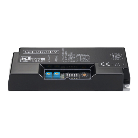
ITOH DENKI CB-016BP7 User manual

ITOH DENKI
ITOH DENKI Power Moller 24 CBM-105FN User manual

ITOH DENKI
ITOH DENKI POWER MOLLER 24 CBM-103FN User manual

ITOH DENKI
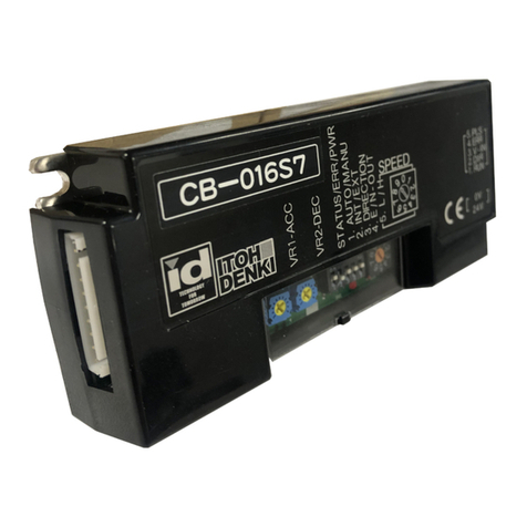
ITOH DENKI CB-016 series User manual

ITOH DENKI
ITOH DENKI POWER MOLLER 24 HBM-604BN User manual

ITOH DENKI
ITOH DENKI POWER MOLLER 24 HBK-608FN User manual

ITOH DENKI
ITOH DENKI POWER MOLLER HBV-609 Guide

ITOH DENKI
ITOH DENKI POWER MOLLER HBM-604BN User manual

ITOH DENKI
ITOH DENKI Power Moller 24 Series User manual