G203V VACUUM INSTALLATION NOTES:
(April 29, 2008)
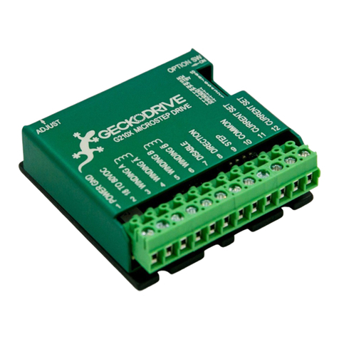
Thank you for purchasing the G203V drive. The G203V is Geckodrive’s new generation CPLD-based microstep
drive. It has short-circuit protection for the motor outputs, over-voltage and under-voltage protection, over-
temperature protection, reversed power supply polarity protection and will survive accidental motor disconnects
while powered-up. The “V” in G203V stands for “Vampire” as in unkillable.
The G203V uses a synchronous PWM design that is absolutely silent when the motor is stopped or turning slowly.
It virtually eliminates stopped-motor heating regardless of power supply voltage. The G203V is a jumper-free drive.
There are no internal user settings at all so there is no need to ever remove the drive cover at all.
The STEP, DIRECTION and DISABLE inputs are opto-isolated. All three inputs work with 2.5V, 3.3V or 5V logic
drive signals. The input drive current is now 2.5mA at 2.5V so almost all logic family (74LS, 74HC, etc.) can be
used to drive these inputs. The COMMON return for the signals is controller ground referenced instead of +5VDC.
This greatly eases the drive to controller interface.
There are no unusual STEP to DIRECTION timing restrictions. Stepping occurs on the positive edge of the STEP
pulse. The DIRECTION input must be true 200nS before and after this STEP pulse edge.
The G203V Microstep drive is warranted to be free of manufacturing defects for 1 year from the date of purchase.
Anyone who is dissatisfied with it or is unable to make it work to their satisfaction for any reason will be cheerfully
refunded the purchase price (but not shipping costs) if the G203V is returned within 15 days of the purchase date in
a cosmetically and electrically undamaged condition.
PLEASE READ FIRST BEFORE USING THE G203V
Before you start you must have a 2-phase hybrid PM step motor (ordinary 1.8 or 0.9 degree per step motor), a DC
power supply suitable for the motor and a current set resistor. The motor’s rated phase current must not be more
than 7 Amps. The power supply voltage must be between 15VDC and 80VDC unregulated. The current set resistor
may be a 1/4-Watt, 5% part. Finally have a STEP, DIRECTION and DISABLE (if needed) source available.
G203V TERMINAL WIRING
TERMINAL BLOCK WIRING:
(TERM. 1) POWER GROUND Connect the power supply ground to term.1
(TERM. 2) +15 TO 80 VDC Connect the power supply “+” to this terminal
The power supply voltage must be between 15 VDC and 80 VDC. The maximum power supply current required is
equal to the motor’s rated phase current. An unregulated power supply may be used so long as the voltage stays
between the specified limits; keep the power supply ripple voltage to 10% or less for best results.
CAUTION! Power supply voltage in excess of 80 VDC will blow the G203V internal fuse.
CAUTION! Reversed power supply polarity will blow the G203V internal fuse.
CAUTION! Never put a switch on the DC side of the power supply! This will damage, if not destroy, your drive!
The choice of power supply voltage depends on the required high-speed performance from the motor; doubling the
voltage doubles the motor’s high-speed power. In all cases the power supply voltage should be no less than 4
times or no more than 20 times the motor’s rated voltage. The motor may not run as smoothly as possible if the
power supply voltage is less than 4 times or more than 20 times the motor’s rated voltage. A power supply voltage
greater than 20 times the motor’s rated voltage may overheat and damage the motor. Motor winding inductance
should be 500 uH or greater.
A more accurate calculation of power supply voltage is to find your motor’s inductance, and put it into the following
equation.
32 * (√mH inductance) = Power Supply Voltage
