wavestore WV-CT-4F User manual

WV-CT-4F
Wavestore Vision Thermal
Mini Bullet IP Camera
Installation Guide
Before installing and using the camera,
please read this manual carefully.
Be sure to keep it handy for future reference.

2
INTRODUCTION
03 Important Safety Information
06 Product & Accessories
07 Part Name
INSTALLATION
08 Installation
09 Cabling
SPECIFICATION
11 Dimension
Contents

3
Safety Information
POWER
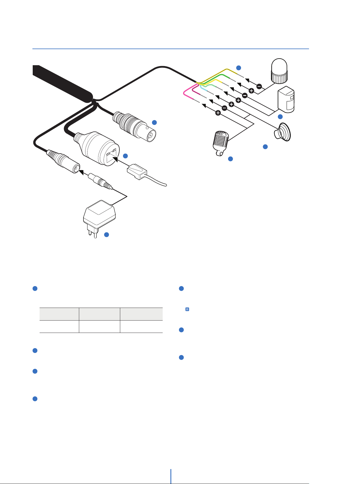
1. Use only standardized adapters written in the manual.
Incorrect connection of the power source can cause fire,
electric shock, or failure.
2. If there is smoke or a strange smell from the power
source, disconnect the power immediately and contact
the service center or purchasing office. If you continue to
use it as it is, it can cause fire and electric shock.
3. Disconnect the power plug from the outlet before
connecting to the power terminal block.
INSTALLATION
1. Install it according to the temperature and humidity environment
suitable for the product specifications. Otherwise, it can cause
fire and electric shock.
2. Thunder and lightning can cause problems with the camera.
When installing, be careful to minimize damage caused by
lightning such as grounding.
3. Do not place conductive materials (drivers, coins, metal
sticks, etc.) and water-filled containers on the camera. It
causes injuries caused by fire, electric shock, and falling.
4. If you want to move the installed product, turn off the
power and move it or reinstall it. Otherwise, it can cause
fire and electric shock.
5. Do not install it in places where there is a lot of moisture,
dust, soot, etc. It causes fire and electric shock
.
6. Avoid places where direct sunlight comes in or where heat
comes out, such as heating appliances. It causes fire and electric
shock.
CLEANING
1. Do not spray water directly on each part of the product
when cleaning. It causes fire and electric shock.
POWER
1. Use the power line after fixing it firmly to the power connection
terminal. Incomplete connection can cause a fire.
2. Do not extend the adapter output cable. If you need to
install the power cable extension, please contact the
service center.
3. Use insulated power for PoE connected external power.
INSTALLATION
1. It is recommended not to touch the lens when installing
the product as the factory ships with a focus adjustment
completed during the manufacturing completion
inspection phase.
2. Avoid installing cameras facing bright lights like sunlight.
Causes damage to the image sensor.
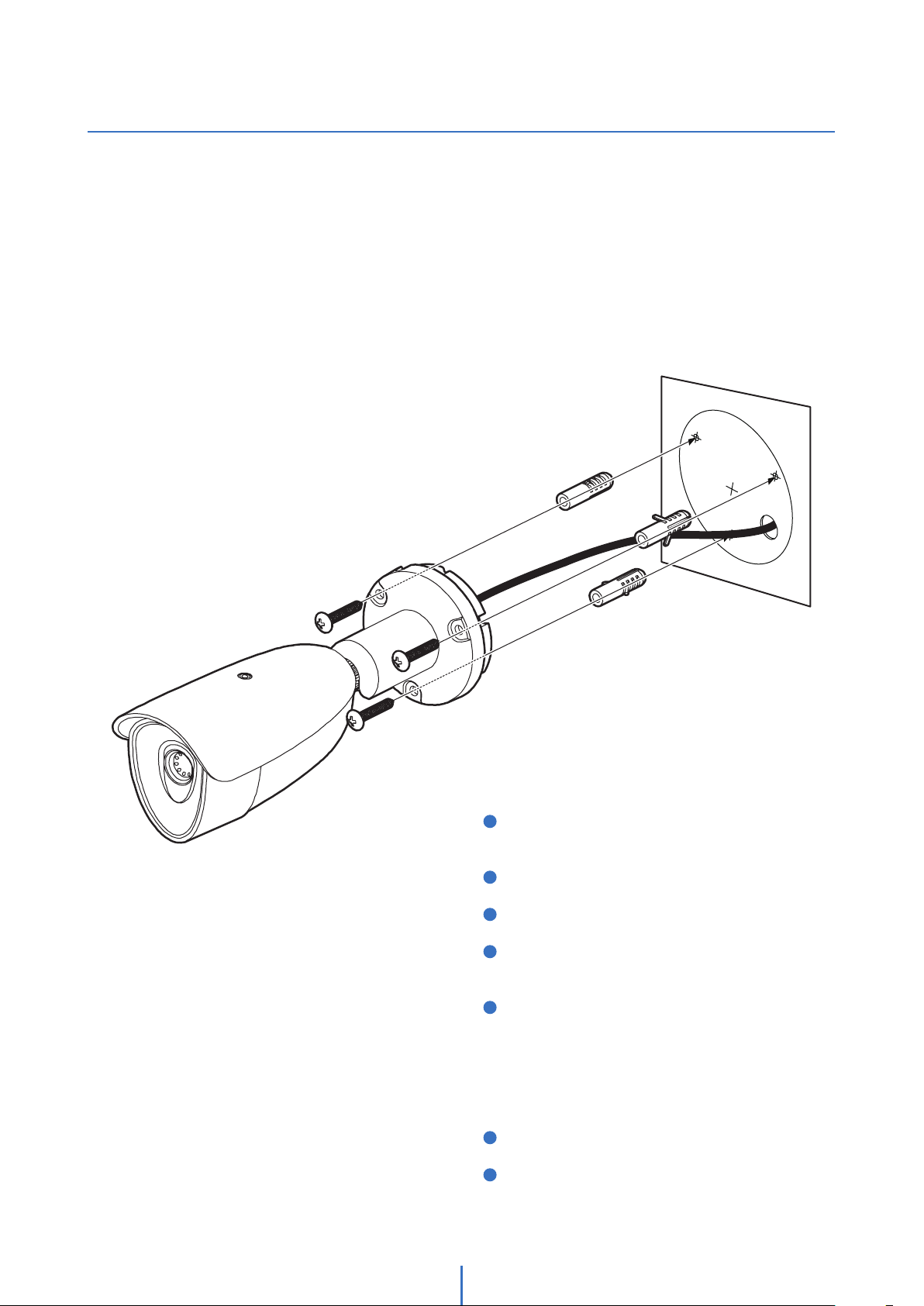
3. Make sure it safe and securely when installing camera on
the wall or ceilling. This can cause injury by the fall.
4. Do not connect multiple cameras to one adapter. Excess
capacity causes abnormal heat and fire.
5. Wear protective gloves when installing/uninstalling the
camera. This causes burns caused by high temperature
on the surface of the product.
6. Don't drop or shock the product. Please stay away from
places where vibration is severe or magnet types are
present.
7. Install it in a well-ventilated place. This can cause fire and
failure.
CLEANING
1. Wipe the contaminated surface with a clean, soft, dry
cloth or wet the soft, dry cloth to prevent water from
flowing, then wipe the contaminated area.
These instructions are intended to ensure that the user can use the product correctly to avoid danger or property loss.
If the product is not functioning properly or damaged, contact the service center or purchasing office.
Warnings
Serious injury or death may be caused
if any of these warnings are neglected.
Cautions
Injury or equipment damage may be caused
if any of these cautions are eglected.

4
Installation and Use Precautions
1. The battery (battery pack or equipped battery) must not be exposed to excessive heat such as sunlight, fire, etc.
2. Do not disassemble the camera at your discretion.
3. If you forcefully install the product with excessive force, malfunction can damage the camera.
4. Do not punch or shake the camera and be careful not to damage the camera with careless storage or malfunction.
5. Be careful not to install the camera in a rainy or humid place, and do not leave it in a wet place.
6. Installing or using the product in water can cause serious product failure.
7. Do not install the product if there is chemical or vapor in the place where the product is installed, or if it can be generated.
8. Be careful not to get chemicals on the surface of the product when installing the product. Chemical solvents such as cleaning
agents and adhesive components can cause fatal damage to the surface of the product.
9. Do not install it near the kitchen or cooking table as edible oil such as soybean oil can also cause product damage and
deformation. It can cause product damage.
10. Be careful not to get foreign substances on the Micro SD card terminal. If there is any foreign substance, wipe it with a soft
cloth.
11. Data will not be saved at the end of the life of the Micro SD card. In this case, purchase a new Micro SD card.
12. Moisture may occur in the glass of the camera when the new product box is opened (or when the product is initially running).
The generated moisture is removed by a Gore vent attached to the camera within hours of the power connectio.
13. For products enclosed with a desiccant or card-type absorbent, please install it according to the manual.
14. Use only with cart, stand, tripod, bracket, or table specified by the manufacturer,
or sold with the apparatus.
15. Unplug this apparatus when a cart is used. Use caution when moving the cart/apparatus
combination to avoid injury from tip-over.

5
Disposal of Old Appliances
1. The symbol marked in the product, will follow and covered by the Europe Directive 2002/95/EC.
2. All electornic disposal of waste is differenct by the government or locally, so so it need to check.
3. The correct disposal of your old appliance will help prevent potential negative consequences for
the environment and human health.
4. For more detailed information about disposal of your old appliance, please contact your city office,
waste disposal service or the shop where you purchased the product.
This equipment has been tested and found to comply with the limits for a Class A digital device, pursuant to part 15 of the FCC Rules.
These limits are designed to provide reasonable protection against harmful interference when the equipment is operated in a commercial environment.
This equipment generates, uses, and can radiate radio frequency energy and, if not installed and used in accordance with the instruction manual, may cause
harmful interference to radio communications. Operation of this equipment in a residential area is likely to cause harmful interference in which case the user
will be required to correct the interferenece at his own expense.

6
Introduction -
Product & Accessories
Torx Wrench
Template Sheet
Screw &
Plastic Anchor - 3pcs
Camera
Cables
Please check if all the camera and accessories are included in the package.
Quick Manual
Waterproof cap & Gasket
& Rubber 2ea
(Black : ø4 / White : ø5)
Note : Cable thickness 4.5ø to 5.5ø uses a black rubber, and over 5.5ø uses a white rubber.

7
Introduction -
Part Name
RJ-45 Connector
DC Power Jack
Waterproof Cap
BNC Cable
Audio, Sensor,
Alarm Cable
Sunshield
Lens
Bracket

8
Installation -
Installation
Before installing your camera, you have to read the following cautions.
1. You have to check whether the location can bear five times of the weight of your camera.
2. Don’t let the cable to be caught in improper place or the electric line cover to be damaged.
Otherwise it may cause a breakdown or fire.
3. When installing your camera, don’t allow any person to approach the installation site. If you have any valuable things under the
place, move them away.
1Drill three holes on the installation surface based on the
provided installation template.
2Insert the plastic anchors into the holes.
3Install the provided ferrite core on the cable.
4Attach the provided wall cushion to the bottom of the
camera’s pan/tilt bracket.
5Fix the camera to the installation surface.
A. Align the screw holes of the camera’s pan/tilt bracket and the
plastic anchors.
B. Insert the provided screw into the plastic anchors through the
screw holes of the camera’s pan/tilt bracket.
C. Tighten the screws firmly into the plastic anchors.
6Connect all the necessary cables.
7Adjust the angle.

9
Installation -
Cabling
1. Using a PoE-Enabled Switch
The Camera is PoE-compliant, allowing transmission of
power and data via a single Ethernet cable.
PoE eliminates the need for the different cables used to
power, record, or control the camera. Follow the illustration
below to connect the camera to a PoE-enabled switch using
an Ethernet cable.
2. Using a Non-PoE Switch
If a PoE-enabled switch is not used, use a power adaptor
for power transmission and non-PoE switch for data
transmission.
Follow the illustrations below to connect the camera
without a PoE-enabled Switch.
Two Options
Use a PoE-enabled swtich to connect data and power through a single cable and begin viewing and recording images instantly.
A non-PoE switch will require an adaptor for power transmission.
Ethernet Cable Ethernet Cable
Power
How to connect to the network through the water proof cable
Insert the Lan cable into the rubber first as (a) below.
Put the Lan cable into (b), then (c) will be assembled to
(b) tightly. As a final step, (d) need to be assembled to (c)
without making any space.
bc
d
a

10
Installation -
Cabling
1Power Connection
Please, check the voltage and current capacity of rated
power carefully.
2Network Connection
Connect the crossover cable into the RJ-45.
3BNC Connection
Used to connect video output device such as monitor
using the BNC coaxial cable.
4Audio Input
Connect the ‘Audio In’ cable of the camera to the device
like microphone.
AUDIO IN : PINK
AUDIO GND : PINK + DOT
AUDIO OUT : SKYBLUE
DI : SKY GREEN
DI COM : YELLOW
DO1 (N.O) : GREEN
DO1 COM : YELLOW + DOT
5Audio Output
Connect the ‘Audio Out’ cable of the camera to device like
speaker.
Audio Out supports only RTSP Back channel function.
It plans to make it available on the web later.
6Alarm Input/Sensor
Cable of the sensor/alarm input device should connect to
Yellow and Sky Green line of the Alam cable.
7Alarm Output
It connects to the alarm lights, siren or lamps and the
sensor types are normal open and normal close.
Cable of the alarm output device should connect to DO1
(N.O.) and DO1 COM of the cable slot.
1Power
2Network
3BNC
5Audio Output
4Audio Input
6Alarm In
7Alarm Out
Rate Power Power
Consumption PoE
DC 12V 11.9W IEEE 802.3af class3

11
Specifications -
Dimension
Unit : mm
61 69
58
207.5
76
190.5
171.5
80
Other manuals for WV-CT-4F
1
Table of contents
Other wavestore Security Camera manuals

wavestore
wavestore Vision WV-8S-180-AI User manual

wavestore
wavestore WV-12F-360M-AI User manual

wavestore
wavestore WV-10M2-27V13 User manual

wavestore
wavestore Vision WV-5D-28F User manual

wavestore
wavestore Vision WV-8D-27V13-AI User manual

wavestore
wavestore WV-2B-28V12 User manual

wavestore
wavestore Vision 4K User manual

wavestore
wavestore WV-8D-27V13 User manual

wavestore
wavestore WV-5B-27V13 User manual

wavestore
wavestore WV-5D-27V13 User manual