WavestoreUSA Video Recording System User manual

Wavestore
Video Recording System
Installer Quick Start Guide
Version 5.40
Reference: WSUSA-MAN-008-002
WavestoreUSA
4430 W Tiffany Dr
West Palm Beach, FL 33407
USA
For Technical Support
P: +1 877.221.0426
E: support@wavestoreusa.com
W: www.wavestoreusa.com

WSUSA-MAN-008-001 1
Index:
Preface .............................................................................................................................................................................. 2
Install Checklist ................................................................................................................................................................. 2
Section 1 Introduction .................................................................................................................................................. 3
Section 2 Hardware Installation.................................................................................................................................... 4
2.1 Box Contents..................................................................................................................................................... 4
2.2 Installation Considerations ............................................................................................................................... 5
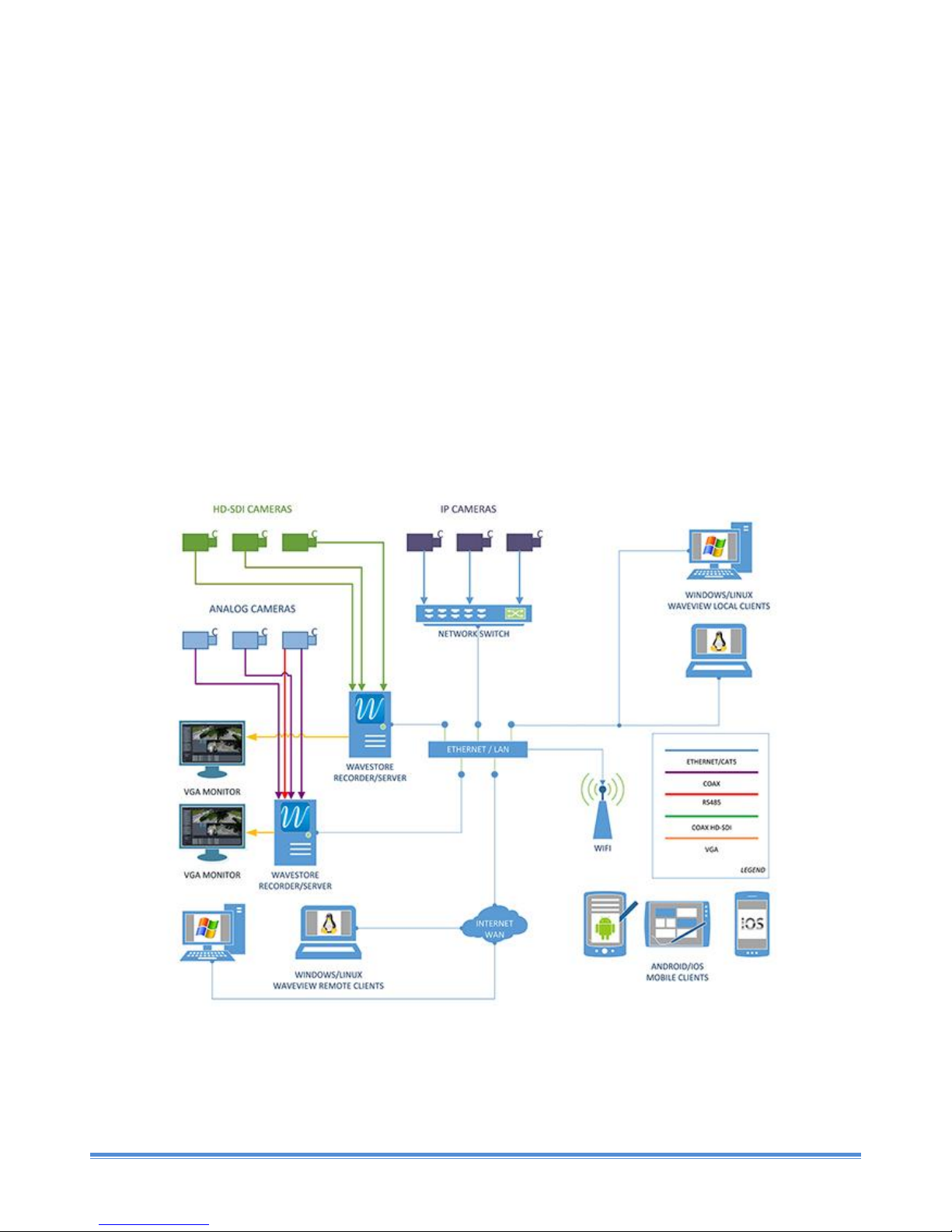
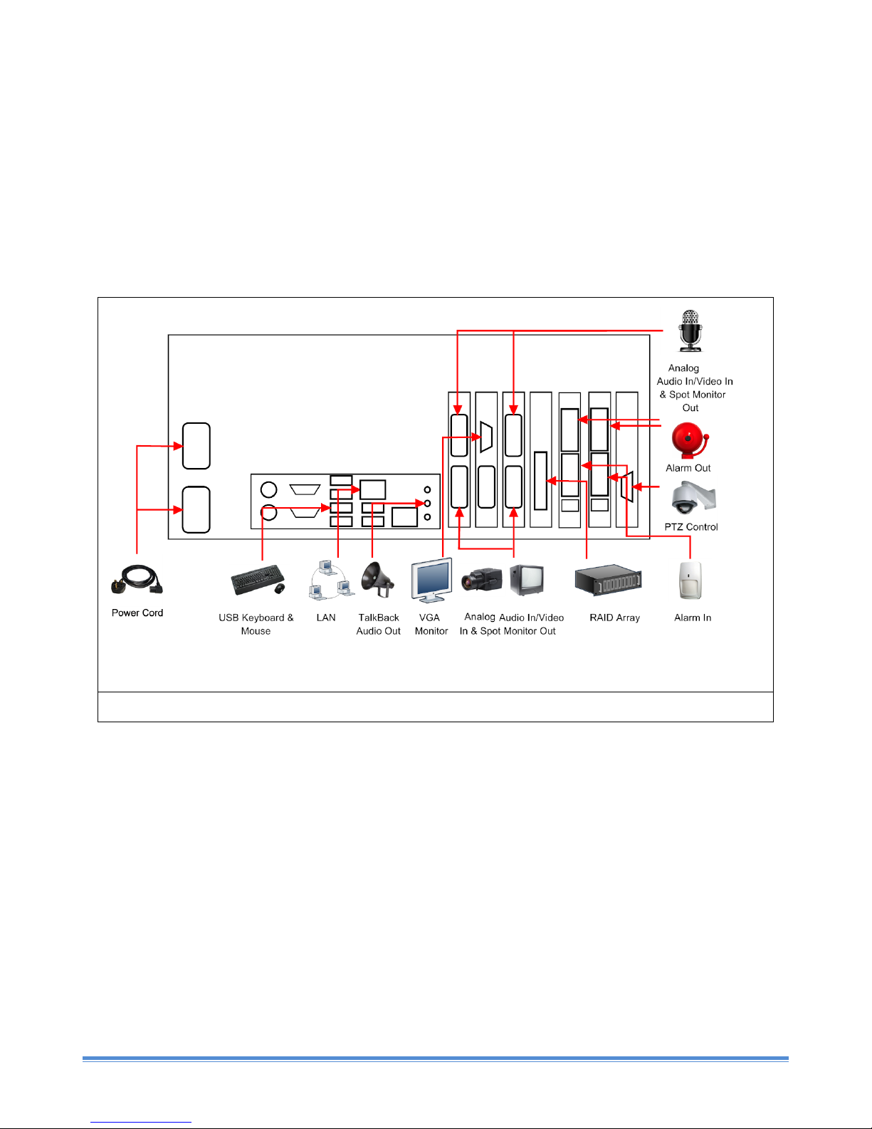
2.3 Hardware Connection Schematic...................................................................................................................... 5
2.4 Stretch Compression Card Connections ........................................................................................................... 6
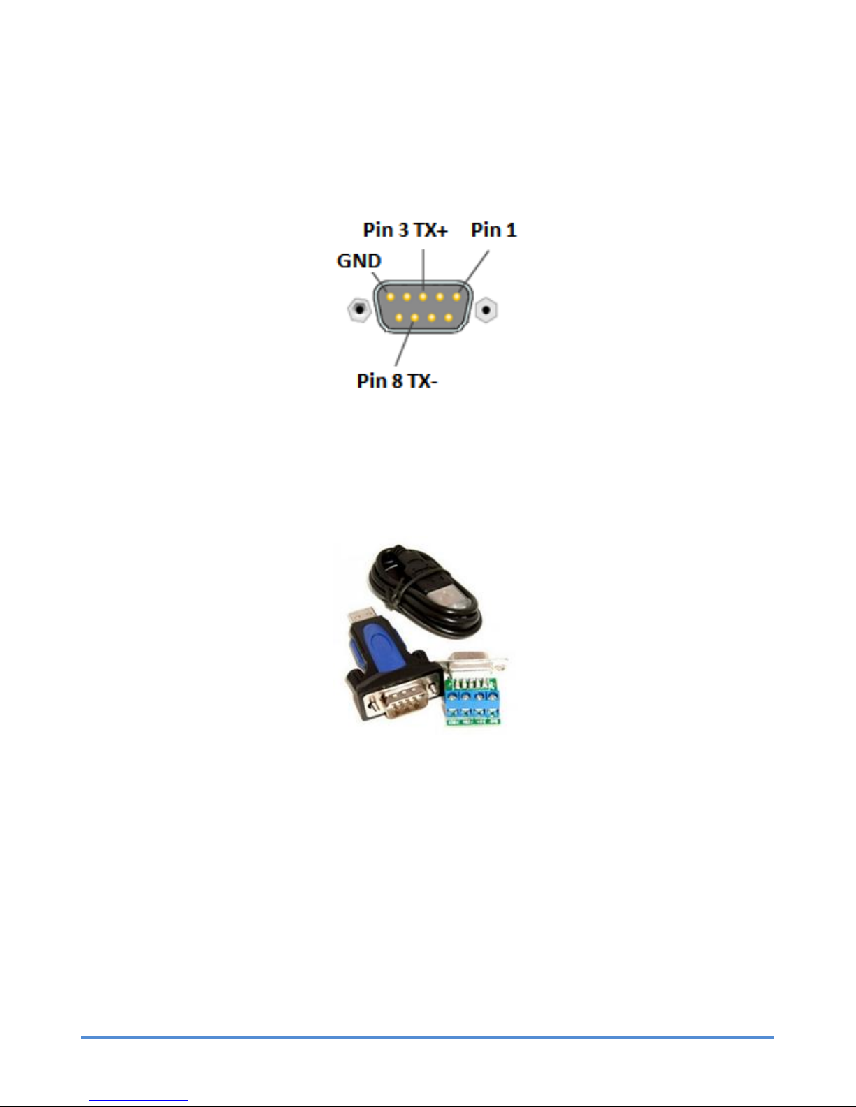
2.5 RS485 Connection for PTZ Control.................................................................................................................... 7
2.5.1 Internal RS485 card................................................................................................................................... 7
2.5.2 External USB-RS485 card........................................................................................................................... 7
2.6 Stretch Alarm Board Connections..................................................................................................................... 7
2.7 USB Alarm Board Connections.......................................................................................................................... 8
2.8 Monitor Connection.......................................................................................................................................... 9
Section 3 Configuration..................................................................................................................................................... 9
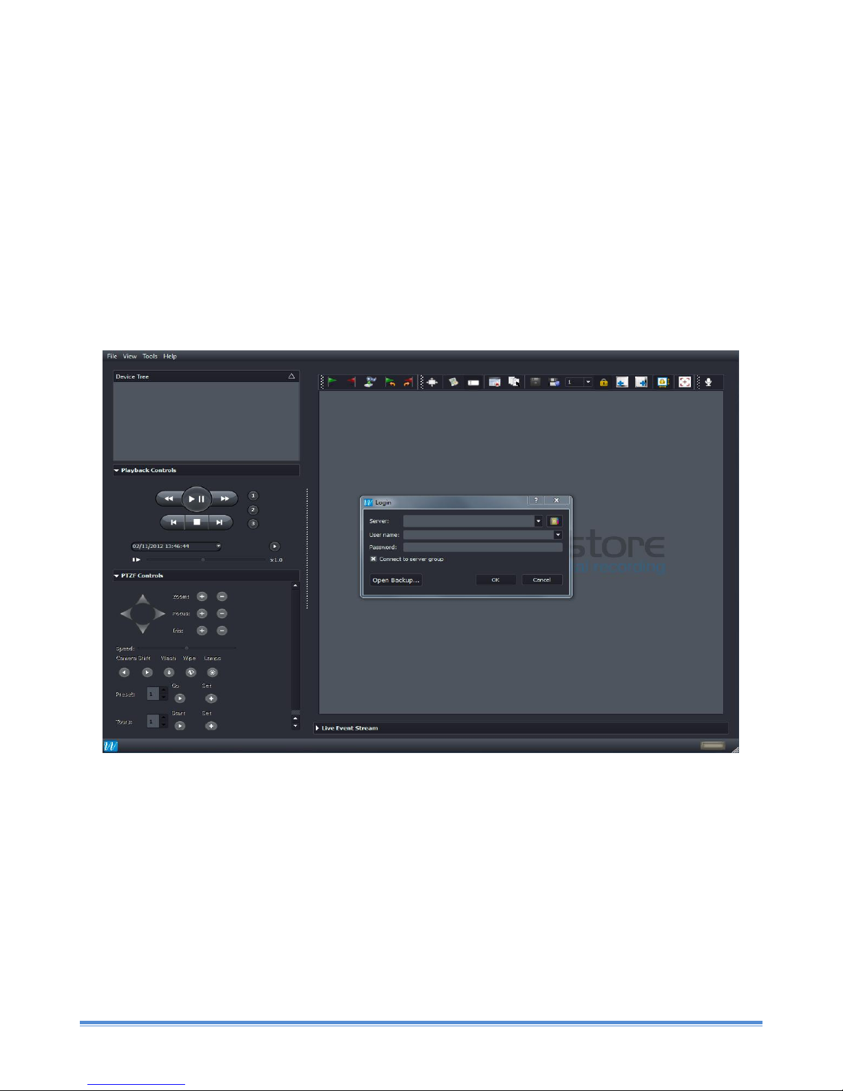
3.1 Logging into Server ................................................................................................................................................. 9
3.2 Live View Screen ............................................................................................................................................. 11
3.3 Time & Region................................................................................................................................................. 12
3.4 Network Connection ....................................................................................................................................... 16
3.5 Video Format................................................................................................................................................... 16
3.6 Enabling Analog Cameras................................................................................................................................ 18
3.7 Enabling IP Cameras........................................................................................................................................ 19
3.7.1 Configuring ONVIF cameras for Recording ............................................................................................. 19
3.7.2 Configuring non-ONVIF cameras for Recording...................................................................................... 24
3.8 Setting up Recording Tracks for Analog and IP Cameras................................................................................ 28
3.9 Configuring User Accounts on the Server ....................................................................................................... 29
3.10 Checking Live View from Cameras .................................................................................................................. 32
3.11 Checking Recording using Quick Search ......................................................................................................... 34
3.12 Closing Video Displays..................................................................................................................................... 39
3.13 Shutting down the Server ............................................................................................................................... 40
3.14 Logging out from the Server ........................................................................................................................... 41
Section 4 Accessing Wavestore Server from Client PC .........................................................................................................42
4.1 Minimum PC Requirements.........................................................................................................................................42
4.2 WaveView Client Software installation process on a Windows PC........................................................................42
4.4 Connecting to Server from WaveView client PC.......................................................................................................47
Section 5 –Technical Support.......................................................................................................................................................49
5.1 Introduction....................................................................................................................................................................49
5.2 Frequently Asked Questions ........................................................................................................................................49

WSUSA-MAN-008-001 2
Preface
This document is intended as a quick reference guide for basic installation and configuration of the Wavestore
system, including accessing the server from a networked Windows PC.
For full configuration and user information for the Wavestore system, please refer to the main Wavestore Software
Manual which can be downloaded from the WavestoreUSA website (http://www.wavestoreusa.com).
You can also download the User Quick Start Guide from the same location, which gives details of the user functions
such as Live View, Search, Playback and Backup.
Install Checklist
Hardware Connections
Mains Power connected to Inputs 1, 2 & 3
Audio & Video Inputs connected to Stretch Cards
Alarm Board Inputs/Outputs connected
PTZ Output connected
LAN connected
Main Monitor connected
Spot Monitor connected
Mouse and Keyboard connected
Configuration
Time & Region configured
Network Connection configured
Video Format (PAL/NTSC) configured
Audio/Video Channels configured
Recording Tracks configured
Installer Password changed from default
User Accounts configured
Live View checked from each Camera
1/2/3/4/5/6/7/8/9/10/11/12/13/14/15/16/17/18/19/20
21/22/23/24/25/26/27/28/29/30/31/32
Playback checked for each Channel
1/2/3/4/5/6/7/8/9/10/11/12/13/14/15/16/17/18/19/20
21/22/23/24/25/26/27/28/29/30/31/32
Logged Out from Server
Client Software
Client Software installed on PC
Test Login to Server from PC
Live View checked from a Camera
Logged Out from Server

WSUSA-MAN-008-001 3
Section 1 Introduction
Easy to install and operate, Wavestore Software is able to simultaneously record video images from a wide range of
analog, IP, HD, and megapixel surveillance solutions, including 360-degree and night vision cameras. Up to 128
channels can be recorded simultaneously from up to 32 analog cameras and up to 8 HD-SDI cameras.
The Wavestore system uses two separate software programs:
Wavestore server software (installed on the server), responsible for managing and recording streams from
audio and video inputs
WaveView client software (also installed on the server); provides a user interface to the Wavestore server
software for functions such as Live View/Search/Playback, and also server configuration
WaveView client software can be installed on Linux or Windows PCs, and used to access networked Wavestore
servers. WaveView client software running on the Wavestore server can also be used to access networked
Wavestore servers in the same way.
Whether they are on site or at a remote network location, authorized personnel have quick, convenient, and
effective access to all information even over limited bandwidth.
If there are multiple Wavestore servers at a site, these servers can be configured together as a Server Group
(optional licensed upgrade), allowing a connected WaveView client to access cameras from any of the servers within
that group.
Figure 1.1 –Typical System Configuration

WSUSA-MAN-008-001 4
Section 2 Hardware Installation
2.1 Box Contents
WavestoreUSA Server
Video Connection Cables (channels 1-8/1-16, + spot monitor output) for analog
compression card (factory fitted option)
Audio Connection Cables (channels 1-8/1-16) for analog compression card (factory
fitted option)
Alarm Input/Output Terminal Blocks (factory fitted option)
Power Cord
Wavestore DVD containing server reinstallation software, client installation software
and manuals
Keys for Hard Drive Caddies (if fitted)

WSUSA-MAN-008-001 5
2.2 Installation Considerations
The server should be located in a cool, dry location, which has good ventilation. Exposing the internal components of
the server (such as Hard Disks) to an elevated temperature will result in degraded performance and reduced
operational life.
2.3 Hardware Connection Schematic
The diagram below is just for reference. Other Wavestore servers are similar, but some cables and connectors may
be located differently. Please note that the use of any motherboard or graphic card HDMI outputs is not currently
supported
Figure 2.1 Cabling Connections to Server

WSUSA-MAN-008-001 6
2.4 Stretch Compression Card Connections
Please note that when connecting audio and video and audio inputs to the compression card sockets(s) on the
server, the connections are orientated as follows:
Stretch S6 Compression Cards (two connection sockets)
Compression Card Type
Upper Socket
Lower Socket
8 channel card (DB9 connectors):
Video (Yellow Connectors for Video
Input, Black Connector for Spot
Monitor Output)
Audio (Red Connectors)
16 channel card (DVI connectors):
Audio (Red Connectors)
Video (Yellow Connectors for Video
Input, Black Connector for Spot
Monitor Output)
Stretch S7 Compression Cards (single connection socket)
Compression Card Type
Single Socket
16 channel card (60 pin LFH connector)
Audio (Red Connectors)/Video (Yellow Connectors for
Video Input, Black Connector for Spot Monitor
Output) - ensure the plug is orientated correctly in the
card socket
The first compression card fitted to the server (for Channels 1 –8/16) has a spot monitor output, which can be
programmed to display images from cameras that are connected to that compression card.

WSUSA-MAN-008-001 7
2.5 RS485 Connection for PTZ Control
Wavestore servers supplied with capture cards for analog camera channels are supplied with an RS485 output for
PTZ control.
2.5.1 Internal RS485 card
Some servers have a built in RS485 output, with the pinouts as follows:
Figure 2.5 DB9 pinout for RS485 PTZ control output (female connector)
2.5.2 External USB-RS485 card
Other servers use a USB –RS485 PTZ Converter as below:
Figure 2.6 USB-RS485 converter for PTZ control output
This converter is connected to one of the server USB ports, and before it can used, the server then needs to be
rebooted in order for the converter to be detected by the server software.
The pin outs for TX+ and TX- are marked on the adaptor terminals.
2.6 Stretch Alarm Board Connections
Upper Nine Pin Connector: Alarm Output: 1-8, Ground
Lower Nine Pin Connector: Alarm Input: 1-8, Ground
Two Pin Connector: Not Used

WSUSA-MAN-008-001 8
Figure 2.6 Stretch Alarm Board Connections
2.7 USB Alarm Board Connections
Figure 2.6 USB Alarm Board Connections
The Wavestore server detects the USB alarm board during the server boot up sequence; once communication is
established between the two devices, you will see the red ‘heartbeat’ LED (closest to the USB cable connection) start
to flash every few seconds.
If you wish to add a USB Alarm Board to a server that is already operating, the server must be rebooted after the
Alarm Board is connected, before it can be used.
In the Alarm I/O Devices menu (Section 4.14 in the main Wavestore manual), configure the USB Alarm Board as
Protocol: WaveAlarm, Port: usbX, and Baud Rate: 9600, and assign a block of ID numbers to the inputs and outputs.
Each input/output much have its own unique ID number, if you are using multiple USB Alarm Boards, use a separate
block of ID numbers for the inputs/outputs.

WSUSA-MAN-008-001 9
2.8 Monitor Connection
The server will only detect a monitor if this device is connected and powered up when the server is first booted up.
If the monitor is attached after the server has been booted up, no video display will be visible until the server is
rebooted.
Please note that use of any motherboard and graphic card HDMI outputs is not currently supported.
Section 3 Configuration
3.1 Logging into Server
Once the server has been connected to any other devices being used on the system, press the power button on the
front panel of the server.
The server will take approximately 60 seconds to boot up; during this time a blue/white progress bar will fill from left
to right. Once the server has completed booting up, the login screen will appear as below:
Figure 3.1 WaveView launch screen

WSUSA-MAN-008-001 10
Figure 3.2 WaveView login screen
The default server login is as follows:
Server: localhost
User Name: install
Password: a
In the event that the configured IP address on the server IP clashes with another device on the network, you will not
be able to login on the server box using the server name ‘localhost’. In the ‘Server’ field, replace ‘localhost’ with the
IP address ‘127.0.0.1’, and login as above.
Section 3.4 describes how to reconfigure the server IP address if required.

WSUSA-MAN-008-001 11
3.2 Live View Screen
The Live View screen (menu path View -> Main) is shown below:
Pull Down Device Event Playback PTZF Live Event Video Display Video Display Status
Menus Tree Controls Controls Controls Stream Area Area Toolbar Indicator
Figure 3.3 - WaveView Live View Screen
This Live View Screen contains the following items:
Pull Down Menus
File/View/Tools/Help –these are described in Section 2
Device Tree
Displays a list of the connected Wavestore servers, with active audio/video channels
Event Controls
Start/Stop operation of configured Event Rules (Section 4.13)
Playback Controls
Used for quick search of recorded footage; full search functions are available in the Find
screen (menu path View -> Find)
PTZF Controls
Used for control of Pan/Tilt/Zoom cameras
Live Event Stream
(licensed upgrade)
Licensed upgrade; displays stream of events from connected devices

WSUSA-MAN-008-001 12
Video Display Area
Video Displays from system cameras can be added here
Video Display Area
Toolbar
Used for controlling individual Video Displays
Status Indicator
normally displays Green, changes to Red when a connected server has reported a fault
3.3 Time & Region
Figure 3.4 Time & Region configuration
Follow the menu path View -> Setup -> Devices -> Time and Region to access the Time and Region setup menu.
The server hardware’s own internal clock is set to the UTC time zone. Using the Wavestore software, we can apply
an offset for the local Time Zone, including local daylight saving changes. This action should be carried out before
setting the time itself.
To configure, select the region that you require from the dropdown menu, then click ‘Save’. You will now be
prompted to restart the server.

WSUSA-MAN-008-001 13
Figure 3.5 Time & Region settings –selecting Time Zone
Once the server software has restarted, confirm that the correct time is displayed in the 'Server Time' field. If not,
you can adjust the time manually, as described in Section 4.7.5 below.
Before adjusting the time, confirm that the correct Time Zone has been selected.
To set the time manually, first ensure that the 'Use an NTP server' box is unchecked. Enter the current time, click the
‘Set Time’ button, then click on ‘Save’.
For a small change in time (less than 29 minutes), the server time will slew slowly by approximately 1 second per
minute, until the desired time is reached.

WSUSA-MAN-008-001 14
Figure 3.6 Time & Region settings –Slewing of server time after time has been set manually
For a larger time change (greater than 29 minutes), a reboot of the system will be required (menu path View -> Setup
-> Devices -> Server Administration -> Reboot System). Once the server has rebooted, the server time will move to
the new time. If the server time is modified to coincide with previous recording, then the old recording will be
overwritten. In some cases, it is recommended to reformat the server hard drives after altering the time and date by
a large amount.
Network Time Protocol (NTP) can be used to synchronize the server time with a networked time source. To configure
NTP, check the 'Use an NTP Server' radio button, enter the IP address of the time source in the box provided, and
click ‘Save’ to confirm your changes.

WSUSA-MAN-008-001 15
Figure 3.7 Time & Region settings –NTP Server option selected

WSUSA-MAN-008-001 16
3.4 Network Connection
If the server is to be connected to a Local Area Network, we must configure the IP address of the network adaptor.
Follow the menu path View -> Setup -> Network to enter the Network Settings screen:
Figure 3.8 Network Configuration Menu
Select the eth0 tab, click on the ‘Manually Configure’ radio button, and complete the IP address, subnet mask,
gateway and DNS server (if required) fields. Click on the ‘Save’ icon to save your changes.
A server may have multiple network adaptors, for example if the case of a server that has one adaptor connected to
IP cameras, and the second adaptor connected to the site LAN/client PCs etc.
Each network adaptor on your server is represented by an ‘ethX’ tab. Select the adaptor that you wish to configure,
by clicking on the tab.
Please note that Wavestore servers use TCP port 8601 to communicate. If the server is connected to a Local Area
Network at a site, and is to be accessed via the Internet by PCs running WaveView client software, then port
forwarding must be configured on the local router at the site.
3.5 Video Format
Enter the Device Settings menu (menu path View -> Setup):

WSUSA-MAN-008-001 17
Figure 3.9 Accessing Setup Menu 1
The Device Tree on the left shows the capture devices and camera channels currently active on the server.
Click on the green capture card icon at the top of the Device Tree (each analog capture card will be labeled Mach,
Stretch or Warp), and the configuration settings for that capture card will appear:
Figure 3.10 Devices Menu, Camera Submenu, Video Format Configuration
By default, the Video Encoding format will be configured as ‘PAL’. If you need to change this setting, select ‘NTSC’
from the pull down menu in the ‘Analog Capture’section, then click on the ‘Save’ icon to confirm this change. Repeat

WSUSA-MAN-008-001 18
for any other capture cards fitted to the server.
3.6 Enabling Analog Cameras
To configure an analog camera, first click on the camera name in the Device Tree, the camera name will be
highlighted dark grey.
In the General submenu, click the ‘Enabled’ radio button to enable the camera (‘x’ will appear).
Figure 3.11 Devices Menu, Device Tree
The ‘Stretch Stream Options’submenu configures the two Video Streams (Stream 1 and Stream 2) for the camera
channel; each stream can be configured independently as follows:
Selection of which stream to be used for the live view display (if Stream 2 is active)
Compression Format
Frame Capture Rate
GOP Size
Resolution
Image Quality Settings
Bitrate

WSUSA-MAN-008-001 19
Figure 3.12 Devices Menu, Camera Submenu, Stretch Image submenu
Finally we need to set up the recording track(s) for each enabled camera, as described in Section 3.8.
3.7 Enabling IP Cameras
The current list of IP cameras currently supported by Wavestore servers can be downloaded from here:
http://www.wavestoreusa.com/integrations/supported-cameras/
To add an IP camera to the Wavestore server, follow the menu path View -> Setup -> Devices then click the ‘Add IP
Capture’ button in the lower left corner of the screen.
3.7.1 Configuring ONVIF cameras for Recording
Follow the menu path View -> Setup -> Devices, and click on ‘Discover ONVIF Cameras’ in the lower left hand corner
of the screen.
Table of contents
Other WavestoreUSA Recording Equipment manuals