Smartrise M1000-INDUCTION Installation and operation manual

Page intentionally left blank
Drive Startup Manual M1000-Induction
December 17, 2019 ©2019 Smartrise Engineering, Inc. All Rights Reserved Page i
Document History
Date Version Summary of Changes
October 23,2018
1.0
Initial Submittal
December 17, 2019
2.0
Changed cover page
Updated title name to reflect the type of drive
New document format
Updated Construction section with more detailed
information
Updated Accucoder encoder wiring

Drive Startup Manual M1000-Induction
Page ii © 2019 Smartrise Engineering, Inc. All Rights Reserved December 17, 2019
Page intentionally left blank

Drive Startup Manual M1000-Induction
December 17, 2019 ©2019 Smartrise Engineering, Inc. All Rights Reserved Page iii
Table of Contents
M1000 Drive ...........................................................................................................1
Equipment/Settings Verification..............................................................................1
Grounding Requirements ........................................................................................2
Wiring .....................................................................................................................2
Power .................................................................................................................................... 2
Brake .................................................................................................................................... 3
Motor/Encoder ....................................................................................................................... 3
Construction ........................................................................................................................... 3
Powering Up ...........................................................................................................5
Final Setup ..............................................................................................................5
Auto Tuning ............................................................................................................7
Motor Alignment .................................................................................................................... 7
Operation................................................................................................................8

Drive Startup Manual M1000-Induction
Page iv © 2019 Smartrise Engineering, Inc. All Rights Reserved December 17, 2019
List of Figures
Figure 1: M1000 Induction Drive ...................................................................................................................................1
Figure 2: Example of Parameter Table ..........................................................................................................................1
Figure 3: Ground Bus Terminal......................................................................................................................................2
Figure 4: Example of Construction Wiring.....................................................................................................................4
Figure 5: Breakers ..........................................................................................................................................................5
Figure 6: MAIN MENU – Setup ......................................................................................................................................6
Figure 7: SETUP Menu – Misc ........................................................................................................................................6
Figure 8: MISC Menu – Bypass Term Limits...................................................................................................................6
Figure 9: Bypass Term Limits Menu – NO......................................................................................................................6
Figure 10: Bypass Term Limits Menu – YES ...................................................................................................................7
Figure 11: U9 Autotune .................................................................................................................................................7


Drive Startup Manual M1000-Induction
Page vi © 2019 Smartrise Engineering, Inc. All Rights Reserved December 17, 2019
Page intentionally left blank
Drive Startup Manual M1000-Induction
December 17, 2019 ©2019 Smartrise Engineering, Inc. All Rights Reserved Page 1
M1000 Drive
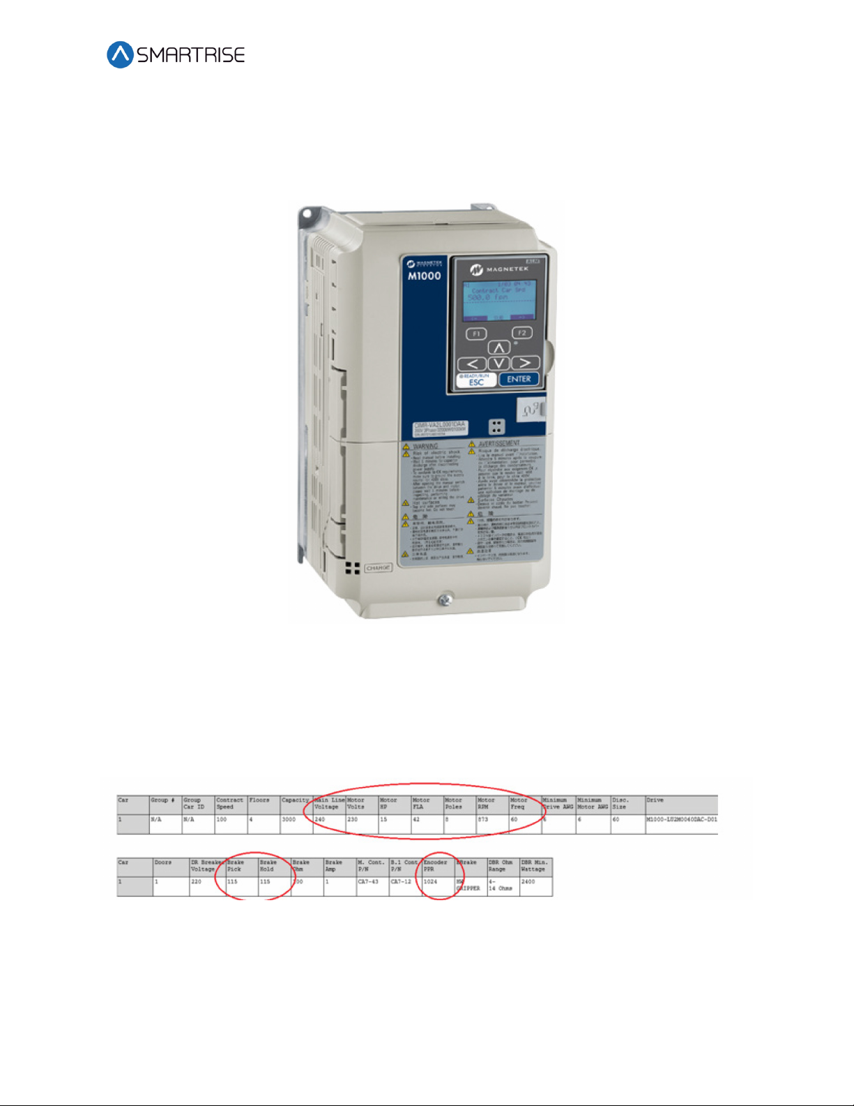
The M1000 drive is an induction AC drive.
Figure 1: M1000 Induction Drive
Equipment/Settings Verification
Set and verify the equipment matches the job specific parameters. See V2 Controller sheet 01
Getting Started Parameter Table for more information.
Figure 2: Example of Parameter Table
Scroll through the motor parameters and verify that they are set to the motor nameplate
values prior to performing the Motor Learn procedure.

Drive Startup Manual M1000-Induction
Page 2 © 2019 Smartrise Engineering, Inc. All Rights Reserved December 17, 2019
Grounding Requirements
NOTE: A proper and effective building ground connection is required for the safe and successful
operation of the controller.
Examples of a proper building-to-controller ground is as follows:
Attach the ground wire to the street side of a water main.
Attach the ground wire to a grounding rod in the pit.
The controller has a common ground bus terminal connection.
.
Figure 3: Ground Bus Terminal
•The building, motor, transformer, and filter(s) must all share a common ground. This
removes ground loops., limits impedance, and routes noise into the ground.
Wiring
A checklist must be completed for every stage of the drive wiring process.
Power
Perform the following to connect power. See V2 Controller sheet 03 Machine Room for job
specific information.
Connect main line power to terminal blocks L1/L2/L3.
Connect the ground wire to the yellow/green terminal block next to L1-L3.
Drive Startup Manual M1000-Induction
December 17, 2019 ©2019 Smartrise Engineering, Inc. All Rights Reserved Page 3
Brake
Perform the following to connect the brakes. See V2 Controller sheet 05 Brakes for job specific
information.
Connect the main brake wiring to terminal K1/K2 and the secondary brake wiring (if
equipped) to terminals J1/J2 located on the terminal block next to the M Contactor.
Jump EB to the terminal listed in the construction box (see V2 Controller sheet 01
Getting Started) and connect either the rope gripper or sheave brake to EBR (if
installed).
Motor/Encoder
Perform the following to connect the drive to the motor and encoder cable. See V2 Controller
sheet 04 Drive and Motor for job specific information.
•Connect motor leads to the M contactor at T1/T2/T3.
•Connect the encoder cable, if applicable, to the PG card located under the top cover.
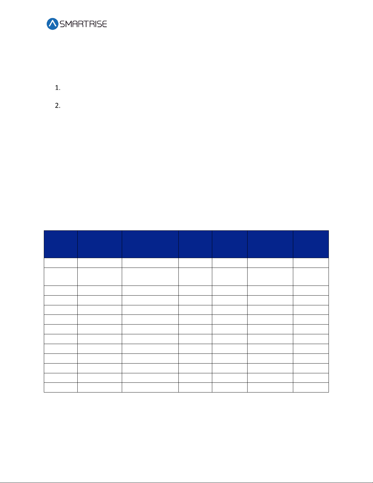
The table below lists the Wiring References for Common Encoders.
Table 1: Wiring References for Common Encoders
Encoder Imperial 35’
Cable 0850357
Imperial 50’/75’
Cable
0850489/0850490
Magil Accucoder Wachendorff
Inducstrial
Encoder
(Canada)
PWR
Red
White
Red
Brown
Brown
Brown
COM
Black
Black
Black
Blue
White
(Shield)
White
A White Purple White
White
Green Green
/A Black/White Gray Brown
Green
Red Pink
B Blue Green Green
Yellow
Yellow Yellow
/B
Red/Black
Blue
Blue
Gray
Black
Blue
Z
Orange
Yellow
Gray
Gray
/Z
Green
Orange
Violet
Red
DATA
/DATA
CLOCK+
/CLOCK-
SHIELD
Shield
Shield
Shield
Shield
Shield
Construction
Perform the following to wire the construction box. See V2 Controller sheet 01 Getting Started-
for job specific information.

Drive Startup Manual M1000-Induction
Page 4 © 2019 Smartrise Engineering, Inc. All Rights Reserved December 17, 2019
Install jumpers between M24 and Input/Output (IO)as per print.
Using an external run box?
a. If using an external run box, go to step 3.
b. If not using an external run box, go to step 5.
Remove factory wires on inputs 521 and 522.
Install the Run Bug UP/DOWN switch to IOs 521 and 522.
Install the Run Bug UP/DOWN SAFE switch to M24.
Install the Temporary Run switch between 120 and SFIN on the CXN board and 120 to
THL, MHL, and BHL on the CXN board.
Are there two sheave brakes and no rope gripper?
a. If there are two sheave brakes and no rope gripper, go to step 8.
b. If there is a rope gripper or single sheave brakes, the process ends.
Install a jumper between EB and SOUT.
Figure 4: Example of Construction Wiring

Drive Startup Manual M1000-Induction
December 17, 2019 ©2019 Smartrise Engineering, Inc. All Rights Reserved Page 5
Powering Up
A checklist must be completed when powering up the drive.
Perform the following to power up the drive.
Apply external power by closing the main line disconnect.
Close the two-pole breaker and all the pushbutton breakers.
Verify the LCD on the Smartrise board and the Magnetek M1000 Drive powers up.
Figure 5: Breakers
Final Setup
A checklist must be completed during final process.
Perform the following to set the Bypass Term Limit.
NOTE: The selected menu within the menu options is shown with a *.
Toggle the Inspection/Normal switch to Inspection.
On the Smartrise Machine Room board, press the left arrow (ESC) button several times
to get to the MAIN SCREEN.
Press the right button to access the Main Menu.

Drive Startup Manual M1000-Induction
Page 6 © 2019 Smartrise Engineering, Inc. All Rights Reserved December 17, 2019
From the MAIN MENU, scroll and select Setup.
Figure 6: MAIN MENU – Setup
From the SETUP menu, scroll and select Misc.
Figure 7: SETUP Menu – Misc
From the MISC menu, scroll and select Bypass Term Limits.
Figure 8: MISC Menu – Bypass Term Limits
From the BYPASS TERM LIMITS menu, set the bypass term limits from NO to YES.
Figure 9: Bypass Term Limits Menu – NO
Drive Startup Manual M1000-Induction
December 17, 2019 ©2019 Smartrise Engineering, Inc. All Rights Reserved Page 7
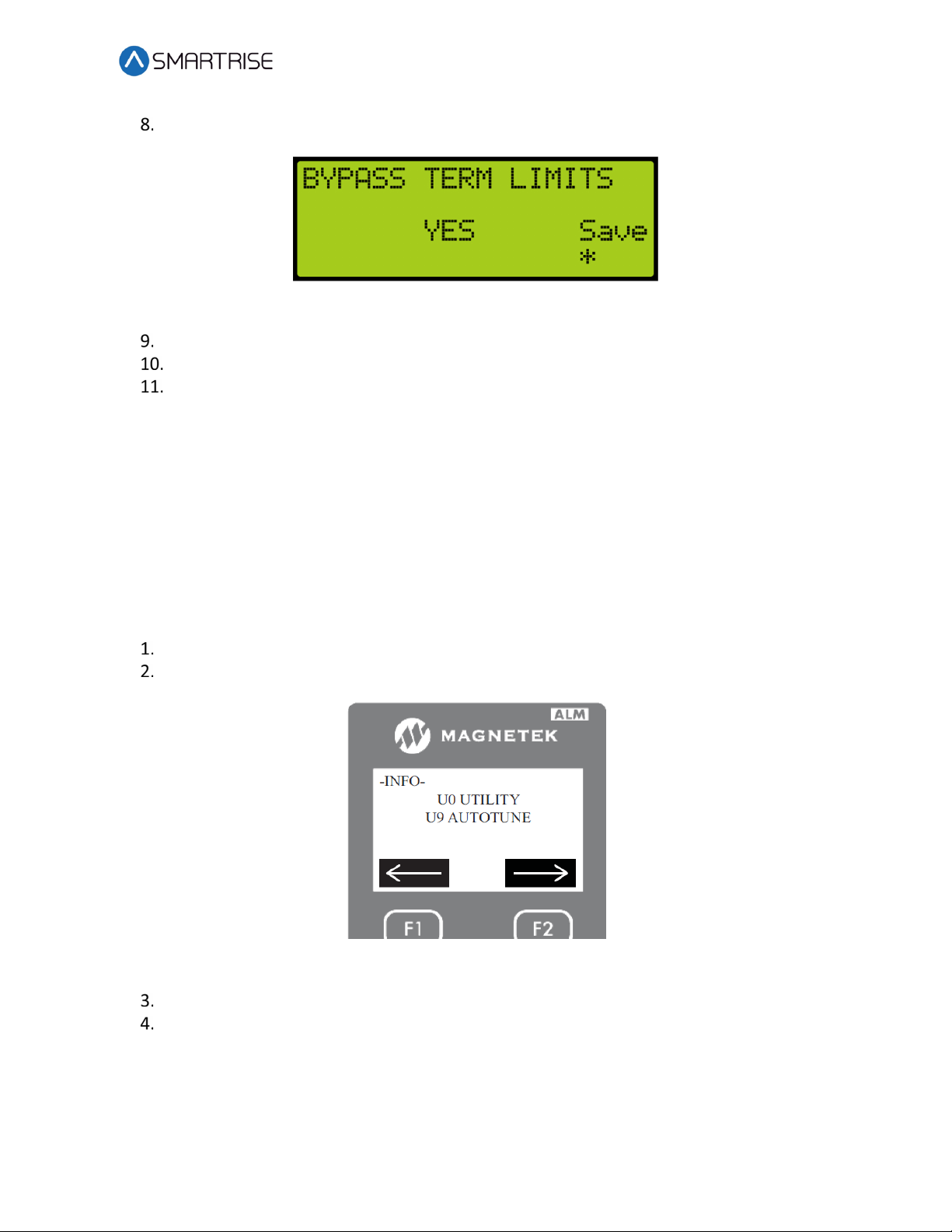
Scroll and change NO to YES.
Figure 10: Bypass Term Limits Menu – YES
Scroll right and press Enter to save.
Press the left button several times to get to the MAIN SCREEN.
Verify the LCD displays Construction Mode on the MAIN SCREEN.
Auto Tuning
Tuning is required for proper motor operation.
A checklist must be completed during the tuning process.
Motor Alignment
Perform the following to align the motor.
Write down the motor data on the motor name plate.
Navigate to U9 AUTOTUNE, then press ENTER.
Figure 11: U9 Autotune
Select Tune No Rotation 1 as the motor tuning method.
Press the DOWN button to enter the following motor data that was written down into
the drive.
a. Enter the motor nameplate horsepower, then press the down button.
b. Enter the motor nameplate voltage, then press the down button.

Drive Startup Manual M1000-Induction
Page 8 © 2019 Smartrise Engineering, Inc. All Rights Reserved December 17, 2019
c. Enter the motor nameplate current, then press the down button.
d. Enter the motor nameplate frequency, then press the down button.
e. Enter the motor nameplate poles, then press the down button.
f. Enter the motor nameplate speed, then press the down button.
g. Enter the encoder pulses per revolution (PPR), then press the down button.
The drive indicates that the ENTER button be pressed to begin the auto-tune, but DON’T
PRESS THE ENTER BUTTON YET!
Press and hold the M contactor button in.
Press the ENTER button on the drive to start the alignment.
Operation
Run the car complete the checklist during the verification process.
Make sure the car is moving without triggering a fault either on the Smartrise SRU board
or the drive. If the SRU board is faulted, see the Smartrise Equipment Installation
Manual. If the Drive is faulted, see the Magnetek M1000 Manual.
Proper Direction: Make sure the car is moving in the same direction as the control
switch on the Run Bug.
a. If the car is moving in only in one direction, swap the ENC 1 ROT DIRECT (C1) in the
M1000 Drive to forward or reverse.
b. If the car is moving in the opposite direction, swap both direction of the ENC 1 ROT
DIRECT (C1) and MOTOR ROTATION (C1).
Are the brakes picking?
a. If the brake is not picking, make sure that the brake is wired correctly (see V2
Controller sheet 05 Brakes) and if there is a second brake installed, verify that the EB
terminal is jumpered to the terminal. See V2 Controller sheet 01 Getting Started for
more information.
b. If the brakes are picking, go to step 4.
Verify the proper voltages on the brake coils by checking the following:
a. During a run command, check for DC voltage between points K1/K2 and J1/J2 if a
second is brake installed. Verify the voltages are also at the brake coil(s) when
commanded to pick.
b. Verify that the voltages match brake coil voltages according to the V2 Controller
sheet 01 Getting Started for the job.
Table of contents
Other Smartrise Industrial Electrical manuals


