Waycon LLD-500 User manual

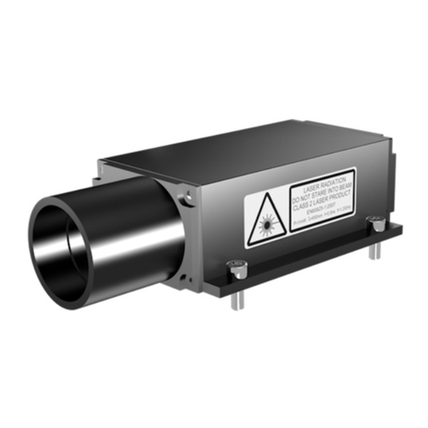
LLD-500
Manual
Dear user,
Please read this operating manual carefully before starting to operate the LLD-500 laser distance meter. This is
the only way to make sure that you will be able to make full use of the capabilities of your new laser distance
meter, and to prevent any dam-age caused by operating errors.
Editorial deadline: 30.11.2016
Documentation number: 012890-001-98HB-G044-C0
WayCon Positionsmesstechnik GmbH
Mehlbeerenstraße 4
82024 Taufkirchen, Germany
Tel.: +49 89 67 97 13-0
Fax: +49 89 67 97 13-250
E-Mail: info@waycon.de
Internet: www.waycon.biz
Revision Status
Date
Release
Revision
Remarks
06.11.2013
001
001
Series
31.01.2014
001
002
SSI
20.03.2014
001
003
Profibus
25.04.2014
001
004
Baud rate, wiring diagrams new, command PB, error
handling
19.09.2014
001
005
SSI + RS232 wiring diagram, SSI transmission rate
10.12.2015
001
006
Chapter 1.3/3.1/3.3/4.9/
6.3.1/6.3.2/6.4.1/6.4.2/6.4.3/6.4.5/6.4.6/6.4.9/6.4.10/6.4.
11/6.4.12/6.4.15/6.4.16/6.5.1/6.5.2/6.5.3/6.7/ 6.8.1/
6.9/9/10
01.11.2016
002
000
2.2. lasercertification
30.09.2017
30.09.2017
30.09.2017
30.09.2017
CE
No part of this manual may be reproduced in any form (photograph, photocopy, microfilm or any other
procedure) without the prior written permission of WayCon Positionsmesstechnik GmbH, nor may con-
tents be processed, reproduced or distributed using electronic systems. This operating manual was
pro-duced with the appropriate care. No liability will be accepted for damage resulting from the non-
ob-servance of the information contained in this manual.
We reserve the right to modify the document following technical advancements.

2
Table of contents:
1. Overview ........................................................................................................................................................5
1.1 Symbols and references.................................................................................................................................5
1.2 Warning signs................................................................................................................................................5
1.3 General information.......................................................................................................................................5
2. Safety advice......................................................................................................................................................6
2.1 Basic safety advice........................................................................................................................................6
2.2 Laser class ....................................................................................................................................................7
2.3 Transport and storage ...................................................................................................................................7
2.4 Cleaning and maintenance............................................................................................................................7
2.5 Service...........................................................................................................................................................7
3. Intended use.......................................................................................................................................................8
3.1 Operating and storage conditions .................................................................................................................8
3.2 Improper use and possible error sources......................................................................................................8
3.3 Warning signs and type plates ......................................................................................................................9
4. Device description...........................................................................................................................................10
4.1 General information.....................................................................................................................................10
4.2 Scope of delivery.........................................................................................................................................10
4.3 Mechanical installation ................................................................................................................................11
4.4 Device cable connector pin assignment......................................................................................................12
4.5 Overview Interfaces.....................................................................................................................................13
4.6 Serial Interface RS232 ................................................................................................................................13
4.7 Serial interface RS422.................................................................................................................................14
4.8 Serially Interface RS485..............................................................................................................................14
4.9 SSI Synchronous Serial Interface ................................................................................................................15
4.10 Profibus-Interface ......................................................................................................................................17
4.11 Laser beam image.....................................................................................................................................18
5. Installation and commissioning.....................................................................................................................18
5.1 Mechanical installation conditions ...............................................................................................................18
5.2 Commissioning............................................................................................................................................19
5.2.1 Preparatory work prior to installation ...................................................................................................19
5.2.2 Installation work checklist ....................................................................................................................19
6. Parameter setup and measuring operation ..................................................................................................20
6.1 General information.....................................................................................................................................20
6.2 Measurement involving moving targets.......................................................................................................20
6.3 Identification ................................................................................................................................................21
6.3.1 ID recognition .......................................................................................................................................21
6.3.2 ID? – Online help .................................................................................................................................21
6.4 Status ..........................................................................................................................................................22
6.4.1 Internal temperature.............................................................................................................................22
6.4.2 PA – Parameter setting ........................................................................................................................22
6.4.3 PR – Parameter Reset .........................................................................................................................23
6.4.4 SA – Average value..............................................................................................................................23
6.4.5 MF – Measuring frequency ..................................................................................................................24

3
6.4.6 MW – Measurement window................................................................................................................24
6.4.7 MUN – Unit of the measured value......................................................................................................25
6.4.8 SF – Scale factor..................................................................................................................................25
6.4.9 OF – Offset...........................................................................................................................................25
6.4.10 SO-Set Offset.....................................................................................................................................26
6.4.11 SD – Data format of the serial interface output..................................................................................26
6.4.12 BR – Baudrate....................................................................................................................................27
6.4.13 SB – Stop bit of the serial output .......................................................................................................28
6.4.14 RS – Serial Port .................................................................................................................................28
6.4.15 AS – Autostart ....................................................................................................................................28
6.4.16 TE - Terminator ..................................................................................................................................30
6.4.18 SP-Separator for parameters.............................................................................................................31
6.4.19 HE – Heating adjustment...................................................................................................................31
6.4.20 MCT – Output/ Modification of the operating mode when starting a measurement using the display
......................................................................................................................................................................31
6.4.21 PB – Setting the Profibus parameters.................................................................................................32
6.4.22 SSA – Profibus slave address ............................................................................................................32
6.4.23 SSI – Setting the SSI parameters.......................................................................................................32
6.4.24 Additional commands.........................................................................................................................33
6.5 Operating modes.........................................................................................................................................33
6.5.1 DM – Individual distance measurement ...............................................................................................33
6.5.2 DT – Continuous distance measurement (distance tracking)...............................................................33
6.5.3 CT – Continuous tracking.....................................................................................................................35
2values for maximum accuracy for the lower and upper limit of measuring range ......Fehler! Textmarke nicht
definiert.
6.6 Q1/Q2/Q3 – Switching output......................................................................................................................36
6.7 QA – Analog output .....................................................................................................................................38
6.8 TRI + TRO Trigger .......................................................................................................................................40
6.8.1 Trigger function ....................................................................................................................................40
6.8.2 TRI – Trigger-Input ...............................................................................................................................40
6.8.3 TRO – Trigger-output ...........................................................................................................................41
6.9 Direct controlling of the LLD-500.................................................................................................................42
7. Serial interface and communication software..............................................................................................44
7.1 Transmission protocol .................................................................................................................................44
7.2 Installation of the communication program .................................................................................................44
8. Profibus ............................................................................................................................................................46
8.1 ID-Number...................................................................................................................................................46
8.2 Connecting conditions .................................................................................................................................46
8.3 GSD-File......................................................................................................................................................46
8.4 Slave address..............................................................................................................................................47
8.5 Profibus termination ....................................................................................................................................47
8.6 Baudrate ......................................................................................................................................................47
8.7 Length of segment.......................................................................................................................................47
8.9 Configuration data .......................................................................................................................................48
8.10 Cyclical data exchange – input (slave -> master) ......................................................................................49
8.11 Cyclical data exchange – output (master -> slave) ....................................................................................49

4
8.12 Parameter data..........................................................................................................................................50
8.13 Diagnostic data..........................................................................................................................................52
8.14 Tips for start-up (Siemens STEP7) ............................................................................................................54
8.15 Error display ..............................................................................................................................................54
8.16 Monitoring..................................................................................................................................................54
8.17 Service program SL5.exe..........................................................................................................................54
8.17.1 Overview ............................................................................................................................................54
8.17.2 Setting a Profibus slave address at the LLD-500 ...............................................................................56
8.17.3 Parameter-Dialog...............................................................................................................................56
8.17.4 Diag Common ....................................................................................................................................56
8.17.5 Diag Alarm .........................................................................................................................................56
8.17.6 Trace ..................................................................................................................................................56
8.17.7 Log-File ..............................................................................................................................................57
9. Error processing..............................................................................................................................................58
10. Technical Data................................................................................................................................................59

5
1. Overview
1.1 Symbols and references
D Enumeration
Note / importantnote
Reference (to a text passage or illustration)
1.2 Warning signs
ThesignCautionwarnsagainstdangerstohealthwhichmayoccurifthisadviceisnotobserved
ThesignAttentionwarnsagainstpossibledamagetothedevice
ThesignInformationpointstoimportantinformation.
This sign indicates that special environmental protection guidelines must be observed when disposing of the
device.
1.3 General information
The laser distance meters of the LLD-500 series have been designed for application in industrial facilities.
Within the measuring range of 15 cm to 200 m the sensors work with a high accuracy of up to + 2.1 mm and at
a variably adjustable measuring frequency of maximally 100 Hz.
Due to the excellent optical measuring performance of the LLD the sensors can be used both indoors and out-
doors, even in case of a high percentage of constant light. Moreover, they can be used for measuring very hot
surfaces such as glowing steel.
When great distances of more than 50 m need to be measured, the sensor can be used in combination with a
reflector. Simple assembly and standard interfaces enable the quick integration of the device into complex
measuring and control systems.
Data can be displayed and parameters can be set using an internal keypad and display or an external communi-
cation program.

6
2. Safety advice
2.1 Basic safety advice
Please read the safety and operating advice carefully, and observe the advice when operat-
ing the LLD-500 laser distance measurement device.
Danger, laser radiation. The LLD-500 must not be opened unauthorized, otherwise laser ra-
diation can be emitted that can cause injuries to the eyes. Please observe all information and
guidelines for operating the laser.
Danger, electric shock
The LLD-500 may only be opened for repair purposes by the manufacturer. If the device is
opened arbitrarily without authorization, all warranty claims will expire.
The operating and storage conditions ( chapter 9) have to be observed. The non- observance
of this advice and the adverse use of the device can lead to injuries of the user or to damage
of the device.
Connectors may not be plugged or unplugged when voltage is applied.
All installation work may only be carried out when no voltage is applied.
The device may only be operated as intended and in faultless condition.
Safety installations must not be rendered ineffective.
Safety and warning signs must not be removed.
Protection degree:
In accordance with the protection degree IP67, the LLD-500 is protected against jet water
and dust, and against short submersion into water.
When operating the device under extreme outdoor environmental conditions, the use of addi-
tional weather protection is recommended (e.g. a cover plate with a short distance to the
LLD-500). Rapid temperature changes can lead to humidity entering the device.
If the device is exposed to humidity, the temperature difference between the de- vice and the
environment may be ± 5K maximum.
The device is not shatter-proof. Do not let the device fall onto the ground, and avoid any agi-
tation.
The device may not be used in explosive environments; otherwise there is the danger of
damage to the LLD-500 and the surrounding equipment, and of injuries of the user.

7
2.2 Laser class
Based on the standard EN 60825-1:2014 the LLD-500 is in correspondence with laser class 2.
When looking into the laser beam accidentally and for a short moment, the eye will be protected by
the eyelid closing reflex. The eyelid closing reflex can be affected by pharmaceuticals, alcohol and
other substances.
2.3 Transport and storage
The LLD-500 laser distance meter is delivered in standard packaging. All kinds of transport are
permitted.It is recom-
mendedtostoretheunitinsidethetransportpackaginguntilitisused.
Pleaseobservethestorageconditions.
2.4 Cleaning and maintenance
The LLD-500 does not require any maintenance. To ensure trouble-free measurements, the optical surfaces
through which the laser beam exits and enters must be free of deposits. Dust can be removed using an air
brush. In case of dirt that is hard to remove, please contact the manufacturer.
The device must not be cleaned using solvents or mechanical tools. Mechanical or electrical modifications of the de-
vice are not permitted.
2.5 Service
In case that repair work is necessary, please send the device to the address below:
WayCon Positionsmesstechnik GmbH
Mehlbeerenstr. 4
82024 Taufkirchen
Deutschland
If you have any questions, please contact us via telephone, fax or e-mail:
Tel.: +49 89 67 97 13-0
Fax: +49 89 67 97 13-250
E-Mail: [email protected]
Internet: www.waycon.biz

8
3. Intended use
3.1 Operating and storage conditions
Operating temperature1
-10°C…+60°C(special type-40°C…+60 °C)
Storage temperature
-40 °C …+70 °C
Humidity
15 %…90 %,non-condensing
1Depending on the type of device
Explanation: The values specified as operating temperature descripe the temperature range in which the LLD
can be used according to the specification.
The operating temperature refers to the internal temperature of LLD and could be approx….
10 kelvins above the ambient temperature (see EN 60204-1).
If LLD-500 operates near the upper limit of temperature range (ambient temperature > 40
°C), the probability of measuring errors will be increased.
A permanent operation of LLD-500 at higher temperatures (ambient temperature > 40 °C)
shortens the lifetime of the sensor. For permanent operation of LLD-500 it is recom-
mended not to exceed an operation temperature of 50 °C, which correlates to a maximum
ambient temperature of 40 °C.
3.2 Improper use and possible error sources
•The unit may be used only as prescribed.
•Please do not remove any labels and type plates.
•Repair work must not be performed by the user. In case of questions or doubt, the manufacturer is to
be consulted. For contact data see section 2.5.
•In order to obtain correct measuring values the following advice is to be observed:
1. Measurements against the sun or onto surfaces with low reflectivity in very bright
environments can result in faulty measurements.
2.
Measurements through glass, optical filters, Plexiglas or other translucent materi
als are possible to
a limited extent but can result in measurement errors.

9
3.3 Warning signs and type plates
Laser label
The LLD-500 works with a class 2 laser.
When looking into the laser beam accidentally and for a
short moment, the eye will be protected by the eyelid
closing reflex. The eyelid closing reflex can be affected
by pharmaceuticals, alcohol and drugs.
This device may be used without any additional safety
precautions when the following advice is observed:
►Do not look directly into the laser beam.
►Do not look at the laser beam using optical
instruments.
►Do not point the laser beam at other people.
WayCon Positionsmesstechnik
82024 Taufkirchen
Made in Germany
YOM 2013
SN 130004
Power 10 ... 30VDC, max. 10W
Op.-temp -10°C ... +60°C
IP67
Type plate
The type plate shown is an example. Type and serial number
(SN) may differ from this image.

10
4. Device description
4.1 General information
The LLD-500 distance meter is available in different versions. Types can be selected based on the required interface
and on the temperature conditions at the place of application.
LLD-500 versions designed for an operating temperature of as low as – 40 °C can be used for applications outdoors
or in refrigerated warehouses. The heating element ensures the operating temperature of the components and free
optics (no condensation) of the LLD-500.
The required connecting cables are available with straight and angular plug-in connectors. In order to prevent the
direct incidence of extraneous light into the device optics, a light protector is available as well that can be screwed
onto the device. Devices with a cable length of up to 10 m are demonstrably EMC-safe.
4.2 Scope of delivery
The device variants of the LLD-500 and its accessories can be ordered under the following part numbers
Designation
Part no.
Remarks
LLD-500-RS
012890-001-22
RS232/ RS422/ RS485
LLD-500-SSI
012890-002-22
RS232/ RS422/ RS485 + SSI
LLD-500-PROF
012890-003-22
RS232/ RS422/ RS485 + PROFIBUS
LLD-500-SSIPROF
012890-004-22
RS232/ RS422/ RS485 + PROFIBUS + SSI
LLD-500-RS-H
012890-041-22
–40°C |RS232/ RS422/ RS485
LLD-500-SSI-H
012890-042-22
–40°C | RS232/ RS422/ RS485 + SSI
LLD-500-PROF-H
012890-043-22
–40°C | RS232/ RS422/ RS485 + PROFIBUS
LLD-500-SSI-PROF-H
012890-044-22
–40°C | RS232/ RS422/ RS485 + PROFIBUS + SSI
Accessories
Device cable 2 m
012840-144-24
Device cable 5 m
012840-145-24
Device cable 10 m
012840-146-24
Device cable 2 m, angular
012890-110-24
Device cable 5 m, angular
012890-111-24
Device cable 10 m, angular
012890-112-24
SSI-cable 2 m
012890-101-24
PB in/out cable, 5 m
012840-170-24
PB in cable jack, 5 m
012840-165-24
PB in cable jack, 10 m
012840-166-24
PB out cable plug, 5 m
012840-160-24
PB out cable plug, 10 m
012840-161-24
PB female protective cap
94366
Female connector
PB male protective cap
94363
Male connector
PB terminating resistor M12
94145
PB 3-pin female connector
94136
PB 3-pin male connector
94133
LLD-500 light protector
012890-250-12
Reflective tape Oralite 5200,
1000x1000
012890-002-28
1 m x 1 m measurements from as low as 50 m
Reflective tape 3M 3279 special
012890-003-28
300 mm x 300 mm measurements from as low as
0.5 m

11
4.3 Mechanical installation
Der The LLD-500 can be screwed on using 3 (underside) or 2 M6 fastening screws respectively (length to be
chosen depending on the counter piece). 3 M6 fastening screws plus washers and washer springs are included
in the scope of delivery.
Figure 1: LLD-500 dimensions
The zero point for measurement is identical with the housing front face.

12
4.4 Device cable connector pin assignment
PIN
Colorcode
RS232
RS422
RS485
Description
A
white
RxD
Rx+
n.c.
RS232Receiverdata/RS422Receiverdata+
B
brown
n.c.
Rx-
n.c.
RS422 Receiver data-
C
green
TRIG
TRIG
TRIG
Triggerinput/output
D
yellow
QA
QA
QA
Analog output (3 mA … 21mA)
E
grey
n.c.
Tx-
B
RS232Transmitterdata/RS422Transmitterdata-
F
pink
TxD
Tx+
A
RS422Transmitterdata+
G
blue
Q3
Q3
Q3
Switching outputQ3
H
red
VCC
VCC
VCC
Supplyvoltage10…30 VDC
J
black
GNDpower
GNDpower
GNDpower
Ground supply voltage
K
violet
Q2
Q2
Q2
Switching outputQ2
L
grey / pink
GNDsignal
GNDsignal
GNDsignal
Groundoutput signal,analog
M
red /blue
Q1
Q1
Q1
Switching outputQ1
Figure 2: Cable jack pin assignment
The shield of the device cable is to be connected to the shield connector of the equipment, e.g. PLC.
►Inverse polarity protection is provided.
►Overvoltage protection is provided up to a maximum of 30 VDC.
►GND
signal
and GND
power
are internal combined without galvanic isolation.
Open, unused cable wires must be insulated.

13
4.5 Overview Interfaces
Figure 3: LLD-500 all interfaces
If LLD-500 types with Profibus interface should be used via serial interface only, the Profibus parameter
PB must be disabled with command PB 0.
4.6 Serial Interface RS232
Figure 4: Wiring of serial interface RS232
The serial interface RS232 can be used for
►Measured data transmission
►
LLD-500 parameterization

14
4.7 Serial interface RS422
Figure 5: Wiring of serial interface RS422
►
Wiring D-SUB9 is not standardized, please check your system.
4.8 Serially Interface RS485
Figure 6: Wiring of serial interface RS485
►
Wiring D-SUB9 is not standardized, please check your system.

15
4.9 SSI Synchronous Serial Interface
SSI will be parameterized via serial interface or the internal display of LLD-500
SSI data interface is optional for LLD-500 (please see the types and order numbers in chapter 4.2). At the
request of a SSI clock LLD-500 starts the output of measuring values and sends the data bit by bit from the shift
register of LLD-500 (Slave) to an external controller (Master).
It could be used all measuring modes of LLD-500. The active measurement mode will be set via serial interface
or Profibus or internal display.
Setup via serial interface → see chapter 6.4.22 SSI und 6.4.16 SE
Setup via internal display → Parameters / BUS / SSI / SSI mode
SSI works independent of Profibus interface.
Transmission rate 150 kHz … 300 kHz
Break duration minimum 25 µs (between 2 bit sequences)
Data length 24 bit or 25 bit (programmable)
Format binary code or gray code (programmable)
Bit string:
1)
Data length 24 bits → bit 23 – 0 = data string
Bit
23
22 –1
0
MSB
LSB
2)
Data length 25 bits → bit 24 = error bit , bit 23 – 0 = Data string
Bit
24
23 –1
0
MSB=error bit
LSB
The inputs (CLOCK) are galvanic isolated, the potential separation is realized up to 500V.
To ensure undisturbed data transfer paired twisted wires are required.
Clock rate
Cable length
< 300 kHz
< 100 m
< 250 kHz
< 150 m
< 200 kHz
< 200 m

16
Figure 7: Wiring of SSI and cable jack pin
The measuring mode will be defined with command AUTOSTART AS.
Please note that by using of parameter measurement window MW (chapter 6.4.6) and / or offset OF (chapter
6.4.9) the distance output value has to be in the positive range (distance value > 0). Otherwise the SSI output
will be 000000.
►SSI Input (Clock+/ Clock-) and system power are galvanic isolated.

17
4.10 Profibus-Interface
►Please see detailed Profibus information in chapter 8
►Profibus INPUT and OUTPUT are galvanic isolated.
Figure 8: Wiring of Profibus Interface

18
4.11 Laser beam image
The laser beam of the LLD-500 has a divergence of 0.13 mrad x 0.17 mrad (width x height). The diameter of
the laser spot on the exit lens measures 4 mm.
The table below shows the size of the laser spot in dependence on the distance. The laser spot has an ellipti-
cal shape.
Distance
Laser spot width
Laser spot height
1 m
5 mm
5 mm
5 m
3 mm
3 mm
10 m
4 mm
5 mm
50 m
6 mm
7 mm
100 m
26 mm
34 mm
200 m
52 mm
68 mm
The above mentioned laser spot holds approx. 50 % of the entire laser energy. An aura with less energy
forms around that spot.
5. Installation and commissioning
5.1 Mechanical installation conditions
There are two different ways to install the LLD-500 laser distance meter. 3 M6 socket cap screws are included in
the scope of delivery.
1. Fastening through one of the side faces
Two M6 screws + washer spring + washer
2. Fastening through the housing bottom
Three M6 screws + washer spring + washer
3. Cable connections
In order to ensure variability in the application of the device, connecting cables with straight or angular con-
nectors are available (also see chapter 4.2).
The cables are not included in the scope of delivery. Please order them as required.
4. Attaching the light protector (optional)
An optional light protector is available for application in very bright environments. Part number: 012890-250-12
The light protector is attached to the front face (laser beam emission point) using three M3x6 screws.
The screws are included in the scope of delivery of the light protector.
When the device is used outdoors under extreme environmental conditions, an additional
weather protector (e.g. cover plate in a small distance to the LLD) is recommended. Other-
wise, moisture may enter the device despite the IP67 due to rapid temperature changes.

19
5.2 Commissioning
5.2.1 Preparatory work prior to installation
►Remove the packaging of the LLD-500.
►Check the delivery for completeness.
►Examine the device and the accessories for damage.
►Examine the connections and cables for damage.
5.2.2 Installation work checklist
The following table suggests a commissioning procedure for the LLD-500, without claiming to be exhaustive.
The user is responsible for the application-specific cabling and for the parameterization of the Profibus
(optional), particularly of the slave address. Thus, the latter are taken as a given.
Where the LLD-500 is taken into operation for the first time, we recommend carrying through the configuration
steps at a laboratory or office.
The device can be configured using either the display or a communication program. For example, the program
HyperTerminal (included in Win32 operating systems) or any other communication program can be used.
In order to parameterize the device using a communication program, the LLD-500 must be connected to supply
voltage and a PC (also see Fig. 2 in chapter 4.4).
SSI and/or Profibus need to be set separately.
No.
Work step
1
Unpack the LLD-500, check it for damage.
2
Mount the LLD-500 at the target location (with 2 screws through the side face or 3 screws through
the bottom) --> see 5.1.
Roughly direct it at the target surface.
3
Plug and firmly screw on the interface cable in the de-energized condition.
4
Connect and firmly screw on the Profibus and SSI connections (optional).
5
Wire the open cable end. Energize. Green status LED must light up.
6
As soon as STATUS LED is green, the red laser beam will be visible. Precondition: AS DT (default
value). Mechanical fine adjustment can be executed.
7
Parameterize the LLD-500 via the menu navigation on the display. Alternatively parameterize the
device using a terminal program.
8
Activate the distance measurement mode (e.g. DT).
9
Start the distance measurement (laser is switched on). Measurement output and Status- LED must
be checked. Stop the distance measurement mode.
Alternative: Start measurement via Profibus.
The SSI measurement mode is to be defined in the AUTOSTART AS command.
10
Final visual check

20
6. Parameter setup and measuring operation
6.1 General information
The LLD-500 is parameterized using the serial interface or the display. Precondition for programming via serial
interface is a connec-tion provided by a terminal program (e.g. HyperTerminal --> see chapter 7).
The set parameters are stored in an EEPROM.
The last entered data will be available upon restarting.
►
Retrieval of parameters
Input PARAMETER <ENTER> <ENTER> = CR = (0x0D)
►
Setting of parameters
Input PARAMETER VARIABLE <ENTER>
The variables are described with the individual parameters.
Several variables are separated by spaces (0x20).
►Starting a measurement (operating mode) Input COMMAND<ENTER>
►Starting a measurement (operating modes) Input COMMAND <ENTER>
►Stopping a measurement <ESC> <ESC> = (0x1B)
►Distances are always entered in 0.1 mm (100 µm).
The scale factor SF has no influence on the input parameters.
Example: Input
3.20 m = 32000
The output values shown in the manual are examples. They may vary depending on the settings and environ-
mental conditions.
Whenever an incorrect or incomplete command is entered, the following responses are shown:
The input does not contain any parameter or command.
e.g.: HELLO<ENTER>
Parameter with current value Entry of a parameter with incorrect figure/ parameterization
e.g.:
Input: SAxxx<ENTER>
Output: SA 10 (where SA = 10 prior to input)
6.2 Measurement involving moving targets
Where measurements involve a moving object or the LLD-500 is moved during measuring, this will have an im-
pact on the accuracy of the measured value.
This must be observed particularly when calculating average values (parameter SA).
Measurement jumps and/or considerable changes in the reflectivity of the target surface can prolong the
measurement period.
In case of a fixed measuring frequency (parameter MF), this may result in no measured value being generated
within the predefined time. A warning or error message will be displayed instead.
Table of contents
Other Waycon Measuring Instrument manuals
Popular Measuring Instrument manuals by other brands

Osborne
Osborne E500R operating instructions

LumaSense
LumaSense Impac INFRATHERM ISR 50-LO user manual

PCB Piezotronics
PCB Piezotronics IMI Sensors M606B61 Installation and operating manual

Elster
Elster EK280 operating manual

Trilithic
Trilithic Model One Operation manual

M Squared
M Squared SolsTiS user manual