Wayne EEAUP250 Service manual

SPECIFICATIONS
POWER SUPPLY REQUIREMENTS 120 V, 60 Hz, Permanent
MOTOR Single Phase
HORSEPOWER 1/4 HP
CIRCUIT REQUIREMENT 15 A (minimum)
LIQUID TEMPERATURE RANGE 40° F- 120° F
620005-001 B 08/18© 2018, WAYNE/Scott Fetzer Company.
CONSTRUCTION
MOTOR HOUSING Thermoplastic
MOTOR SHAFT Thermoplastic
IMPELLER Thermoplastic
VOLUTE Stainless Steel
PUMP DISCHARGE 1-1/4 in. NPT or 3/4 in. Hose Threads
Auto On-Off Water Removal Portable Pump
www.waynepumps.com
PERFORMANCE
Model HP
Discharge 0 ft. 5 ft. 10 ft. 15 ft. 20 ft.
EEAUP250 1/4 Gal/hr 3100 2350 1600 900 250
Operating Instructions and Parts Manual EEAUP250
Please read and save these instructions. Read carefully before attempting to assemble, install,
operate or maintain the product described. Protect yourself and others by observing all safety
information. Failure to comply with instructions could result in personal injury and/or property
damage! Retain instructions for future reference.

EEAUP250Operating Instructions and Parts Manual
2
REMINDER: Keep your dated proof of purchase for warranty purposes! Attach it to this manual or file it for safekeeping.
GENERAL SAFETY INFORMATION
CALIFORNIA PROPOSITION 65
This product can expose you to chemicals, including
DEHP, which is known to the State of California to cause
cancer, birth defects and reproductive harm. For more
information, go to www.P65Warnings.ca.gov.
Ce produit peut vous exposer à des produits chimiques,
notamment du DOP, reconnus par l’État de Californie
comme étant cancérigènes et à l’origine d’anomalies
congénitales et de problèmes de l’appareil reproductif.
Pour plus de renseignements, visiter le site www.
P65Warnings.ca.gov.
GENERAL SAFETY
• Read the manual(s) included with this product
carefully. Be
thoroughly familiar with the controls and the proper
use of the equipment. Follow alll instructions.
• Only persons well acquainted with these rules of
safe operation should be allowed to use the unit.
Risk of fire, explosion and/or death! Pump
is NOT rated for use with flammable/combustible liquids, vapors or
dusts. Do NOT pump liquids that are NOT clear. Failure to follow these
instructions will result in bodily injury or death.
Risque d'incendie, d'explosion et/ou de mort!
La pompe N'EST PAS homologuée pour être utilisée avec des liquides,
vapeurs ou poussières inflammable/combustibles. NE PAS utiliser de
liquides qui ne sont PAS clairs. Le non-respect de ces instructions
entraînera des blessures corporelles ou la mort.
Risk of electric shock. This pump has NOT been
tested for use in swimming pool or marine areas. NEVER place pump in
pools while people are in the water. Failure to follow COULD
result in death or serious injury.
Cette pompe N’a PAS été testée
pour une utilisation dans une piscine ou dans des secteurs
marins. NE JAMAIS placer la pompe dans une piscine
pendant que des gens sont dans l'eau. Le non-respect de cette
recommandation POURRAIT entraîner la mort ou des blessures graves.
DESCRIPTION
This portable, submersible Multi-Use pump is designed for
automatic use in water. The units are equipped with a 9 ft. 3-prong
grounding type power cord. The provided discharge adapter can
be used for convenient attachment to a garden hose.
UNPACKING
Inspect this unit before it is used. Occasionally, products are
damaged during shipment. If the pump or components are
damaged, contact Customer Support at 1-800-237-0987.
SAFETY SIGNAL WORDS
This manual contains information that is important to know
and understand. This information is provided for SAFETY and
to PREVENT EQUIPMENT PROBLEMS. To help recognize this
information, observe the following symbols.
Danger indicates an imminently hazardous
situation which, if NOT avoided, WILL result in death or serious injury.
La mention Danger indique une situation
dangereuse imminente qui, si elle n’est pas évitée, ENTRAÎNE la mort ou
des blessures graves.
Warning indicates a potentially hazardous
situation which, if NOT avoided, COULD result in death or serious injury.
La mention avertissement indique une
situation potentiellement dangereuse qui, si elle n’est pas évitée, risque
d’entraîner des lésions corporelles graves ou même la mort.
Caution indicates a potentially hazardous
situation which, if NOT avoided, MAY result in minor or moderate injury.
MISE EN GARDE La mention mise en garde indique une
situation potentiellement dangereuse qui, si elle n’est pas évitée,
pourrait entraîner des blessures mineures ou modérées.
Notice indicates important information, that if
NOT followed, MAY cause damage to equipment.
This is the safety alert symbol. It is used to alert you to potential
bodily injury hazards. Obey all safety messages that follow this symbol
to avoid possible injury or death.
NOTE: Information that requires special attention.

Operating Instructions and Parts Manual
3
Risk of electric shock! Do NOT handle pump
with wet hands or when standing in water or on a damp surface. Failure
to follow COULD result in death or serious injury.
Risque de choc électrique! NE PAS
manipuler la pompe avec les mains humides ou debout
dans l'eau ou sur une surface humide. Le non-respect de
cette recommandation POURRAIT entraîner la mort ou des
blessures graves.
Electric shock hazard! For installation by a
qualified electrician only. GFCI receptacles will provide protection
against line to ground faults only. The ground fault receptacle does NOT
limit the magnitude of fault current and will NOT prevent an electrical
shock.
Risque de choc électrique! À faire
installer par un électricien qualifié seulement. Les prises
équipées d'un disjoncteur de fuite à la terre fourniront
une protection uniquement contre les défauts entre les
lignes et le sol. Le boîtier du disjoncteur de fuite à la terre ne limite
PAS l'amplitude du courant de défaut et n'empêchera PAS les chocs
électriques.
Wear safety glasses at all times when working
with pumps.
Damage to the power cord or discharge hose
may occur. Use the handle supplied on the pump to carry or move.
APPLICATION AND OPERATION
Do NOT use pump if any part of the housing
switch, probe, or power cord is cracked, broken, or missing.
NE PAS utiliser la pompe si une partie
quelconque du commutateur de boîtier, de la sonde de capteur ou du
cordon d'alimentation est fissurée, brisée ou manquante.
Always disconnect electric supply before
attempting to install, service, relocate, or perform any maintenance. If
the power source is out of sight, lock and tag in open (off) position to
prevent unexpected power application. Failure to do so could result in
fatal electrical shock!
Toujours couper le
courant avant d'essayer d'installer, de réparer,
de déplacer ou d'effectuer toute opération de
maintenance. Si la source d'alimentation est hors de vue, verrouiller et
étiqueter en position ouverte (off) pour éviter une décharge électrique
inattendue. Ne pas le faire pourrait entraîner un choc électrique mortel.
Use polarized grounding type plugs only.
Polarized plugs have one blade slightly wider than the other and can
only be inserted one way into the outlet. Do NOT handle plug connector
near water. Failure to follow these instructions will result in serious
injury or death.
Utiliser seulement des fiches
de masse polarisées. Les fiches polarisées ont une lame
légèrement plus large que l'autre et ne peuvent être
insérées dans la prise que d'une seule manière. NE PAS manipuler
le connecteur près de l'eau. Le non-respect de ces instructions
ENTRAÎNERAIT de graves blessures ou la mort.
This unit is NOT designed for use as a sump
pump or in sump applications, this will void warranty. This unit is NOT
designed for use in septic tanks or underground vaults to pump raw
sewage or effluents. NEVER use in hazardous or explosive locations.
Cette unité n'est PAS conçue pour être utilisée
comme pompe de puisard ou dans des applications de puisard, cela
annulera la garantie. Cette unité n'est PAS conçue pour être utilisée
dans des fosses septiques ou des enceintes souterraines pour
pomper les eaux usées ou les effluents. Ne JAMAIS utiliser dans des
environements dangereux ou explosifs.
1. This pump has been designed with 1-1/4 in. NPT
discharge connection size. Attach pipe or fitting
to the discharge or use the supplied garden hose
adapter. Thread the female end of the garden hose
to the male end of the elbow.
2. Be certain to use a hose washer (not included) on the garden
hose for correct pump operation.
3. For best pump performance, unwind the hose before starting
the pump. This will help remove any kinks or binds in the hose
and allow the unit to pump with less restriction.
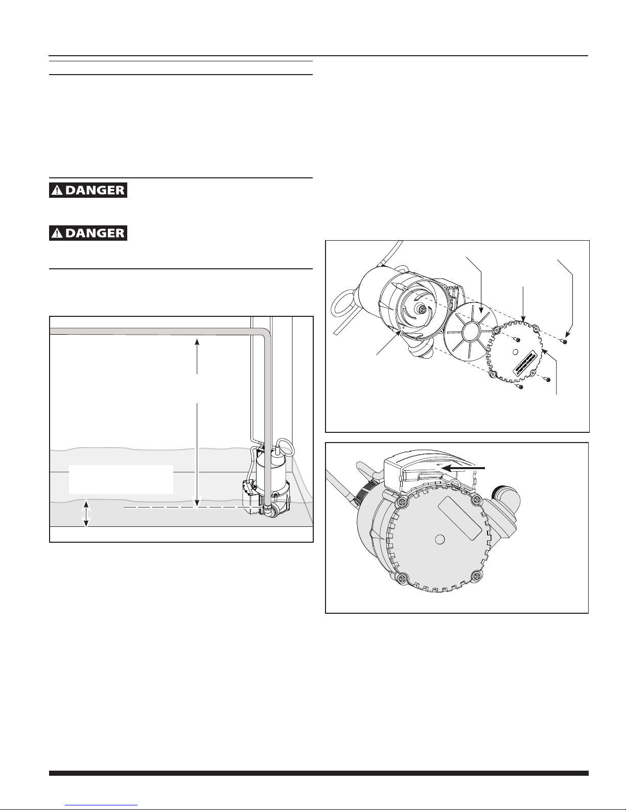
4. Set the pump on a hard, flat surface in the water. Do not set
the pump directly on mud or sand surfaces. This will cause the
inlet to clog.
5. The water level must be at least 1-3/4 inches for the pump to
cycle, prime, and operate. Water levels less than 1-3/4 inches
will not allow the impeller to contact water therefore no water
will be pumped.
Do NOT use pump with wet hands or when
standing in water or on a damp surface when the unit is operating
or fails to operate. ALWAYS disconnect pump power cord from power
source before handling.
NE PAS utilisation pomper avec les mains
humides ou debout dans l'eau ou sur une surface humide lorsque
l'appareil fonctionne ou ne fonctionne pas correctement. TOUJOURS
débrancher le cordon d'alimentation de la pompe de la source
d'alimentation avant toute manipulation.

EEAUP250Operating Instructions and Parts Manual
4
APPLICATION AND OPERATION
6. Plug the pump into a 120 volt GFCI protected outlet. The
pump will start pumping automatically when the water reaches
a depth of 1-3/4 inches. A priming delay of 2 seconds is
programmed into the control to allow time for air to escape
from the pumping chamber.
7. The pump will stop automatically once water has been
removed to a depth of approximately 3/8 of an inch above the
hard surface. The pump will not restart until the water depth
rises to 1-3/4 inches or greater.
8. The pump will not allow itself to run dry. Once the pump
detects that water is no longer being removed, it will shut down
automatically. The pump must remain upright at all times in order
for the water detection to function. Do not allow the pump to
operate on its side or inverted.
Do NOT alter the pump to override the
automatic water detector. The shaft seal depends on water for
lubrication. Overriding this pump feature can cause the pump to run
dry and may damage the shaft seal and cause pump failure and void
warranty.
MAINTENANCE
Pump starts automatically. Always disconnect
electric supply before attempting to install, service, relocate, or perform
any maintenance. Failure to do so could result in fatal
electrical shock.
La pompe démarre
automatiquement. Toujours couper le courant avant
d'essayer d'installer, de réparer, de déplacer ou d'effectuer toute
opération de maintenance. Le non-respect de ces instructions pourrait
entraîner un choc électrique mortel.
1. Periodic cleaning of pump is required to maintain performance
of the pump. Follow the cleaning steps listed below:
a. Unplug the power cord.
b. Remove the four (4) base screws (Figure 2).
c. Remove the base and impeller plate.
d. Remove the debris and make sure the impeller turns freely.
e. Reinstall impeller plate, base, and screws.
f. Use a pin or paperclip to clean the priming hole and air
escape channel.
PUMPING HEIGHT
When water is pumped to an elevated position, any volume that has not
reached the discharge outlet can flow back through the pump when
the pump shuts off. This back-flow can cause the water level in small
areas to rise enough to re-start the pump. A check valve [Check Valve Sold
Separately] is required in this situation. For proper operation, make certain
the check valve is oriented as instructed.
In small areas a check valve is required
to prevent backflow. Without a check valve the pump may cycle
continuously and potentially wear out the pump components.

Operating Instructions and Parts Manual
5
TROUBLESHOOTING
Minimal service is required for this pump. The motor housing of
the pump is completely sealed and requires no internal service. If
pump should fail to operate, perform the following troubleshooting
guidelines:
1. Verify pumping height does NOT exceed 13 feet (See Figure 1).
If pumping height is greater than 13 feet, this pump will NOT
operate.
2. Verify water depth is 1-3/4 inches or greater (See Figure 1).
Do NOT disassemble or alter this product in any
way. Failure to follow these instructions will result in serious injury or
death, and will void warranty.
NE PAS démonter ou modifier ce produit
de quelque manière que ce soit. Le non-respect de ces instructions
entraînerait de graves blessures ou la mort, cela annulera la garantie.
3. To verify pump is operating correctly.
a. Disconnect pump from power source.
b. Connect hose adapter and discharge hose to pump.
13 FT MAXIMUM
PUMPING HEIGHT
Figure 1 - Pumping Height
WATER LEVEL MINIMUM:
1-3/4 INCHES
c. Immerse pump in a bucket or tub of water at least 1-3/4
inches in depth.
d. Place the other end of the discharge hose outside the
bucket, so the water will pump out.
e. Plug power cord into a grounded 120 volt GFCI power
outlet. The pump should start after 2 seconds of detecting
water. Once the pump removes the water to a depth of 3/8
inch, the pump will stop automatically.
f. If pump does NOT operate, unplug power cord and
proceed to maintenance –refer to cleaning instructions.
4. To verify discharge hose is free from a blockage.
a. Connect hose to another water source such as a faucet.
If water flows through hose, return to step 3a. If water is
restricted, verify discharge hose is unwound. Remove all
kinks, bends, or obstructions in hose.
b. If pump is still NOT operating, refer to cleaning instructions
5. If pump runs continuously, unplug the unit. Once unplugged,
check for debris stuck inside the sensor body (Figure 3).
Remove any trapped leaves, debris or dirt.
6. If the pump cycles on and off too often the electronic switch may need
cleaning. Unplug the pump and turn upside down. The sensor should
be checked for debris or build up of mater on the sensor.
PRIMING HOLE
BASE SCREWS (4)
INLET SCREEN/
BASE
IMPELLER PLATE
Figure 2 - Priming Hole Location
WHEN REATTACHING THE BASE (INLET SCREEN), BE SURE THAT
THE "PLUGGED" SCREEN IS ORIENTED BELOW THE SWITCH.
Figure 3 - Remove Debris From Sensor
CLEAN DEBRIS
INSIDE SENSOR

EEAUP250Operating Instructions and Parts Manual
6
Troubleshooting Chart
Electrocution Hazard! Pump starts automatically. Disconnect the power before attempting any repairs. Failure
to follow will result in serious injury or death.
Risque d'électrocution! La pompe démarre automatiquement. Couper le courant avant d’entreprendre une
quelconque réparation. Le non-respect de cet avertissement peut entraîner de graves blessures ou à la mort.
Symptom Possible Cause(s) Corrective Action
Pump will not
start or run
1. Tripped home electrical breaker
2. GFCI tripped
3. Low line voltage
4. Defective motor
5. Dirty switch
6. Impeller obstructed
7. Inlet screen clogged
8. Priming hole plugged
1. Reset breaker
2. Check for damaged wiring or moisture
3. If voltage is under 108 volts, check wiring size
4. Replace pump
5. Rinse out switch with clean water (Figure 3)
6. Remove base and impeller plate (Figure 2) check for debris; clean
7. Clean inlet screen (Figure 2)
8. Clean hole, inside volute housing, with a pin or paper clip (Figure 2)
Pump starts and
stops too often
1. Backflow of water from piping
2. Dirty switch
3. Priming hole plugged
1. Install or replace check valve [Sold Separately: 62061-WYN1]
2. Rinse out switch with clean water (Figure 3)
3. Clean hole, inside volute housing, with a pin or paper clip
(Figure 2 on page 3)
Pump will not
shut off or runs
continuously
1. Debris in switch
2. Discharge height exceeds capability
1. Rinse out switch with clean water (Figure 3)
2. Raise pump or reduce discharge height
Pump operates
but delivers little
or no water
1. Impeller obstructed
2. Priming hole plugged
3. Obstructed piping
4. Discharge height exceeds capability
1. Remove base and impeller plate (Figure 2), check for debris; clean
2. Clean hole, inside volute housing, with a pin or paper clip
(Figure 2)
3. Check for kinks, reposition hose or check for debris
4. Reposition pump to reduce discharge height

Operating Instructions and Parts Manual
7
LIMITED WARRANTY
For one year for EEAUP250 model from the date of purchase, from an authorized dealer, Wayne Water Systems will repair or replace, at its option for the original
purchaser, any part or parts of its Multi-Use Pumps or Water Pumps (“Product”) found upon examination by Wayne Water Systems to be defective in materials or
workmanship. Please call Wayne Water Systems (800-237-0987) for warranty instructions. Be prepared to provide the model number and the serial number when
exercising this warranty. All transportation charges on Products or parts submitted for repair or replacement must be paid by purchaser.
This Limited Warranty does not cover Products which have been damaged as a result of accident, abuse, misuse, neglect, improper installation, improper maintenance,
or failure to operate in accordance with Wayne Water Systems’ written instructions.
THIS WARRANTY IS IN LIEU OF ANY AND ALL OTHER WARRANTIES, OBLIGATIONS OR AGREEMENTS, EXPRESSED OR IMPLIED, INCLUDING ANY IMPLIED WARRANTY
OF MERCHANTABILITY OR FITNESS FOR ANY PARTICULAR PURPOSE, AND ANY RIGHTS OR REMEDIES AGAINST ANY PERSON OR ENTITY UNDER THE UNIFORM
COMMERCIAL CODE OR OTHERWISE WITH RESPECT TO THE SALE OF THE PRODUCT. THE REMEDIES AND OBLIGATIONS STATED IN THIS WARRANTY ARE THE SOLE
AND EXCLUSIVE REMEDIES OF AND OBLIGATIONS TO THE OWNER FOR ANY AND ALL MATTERS ARISING WITH RESPECT TO OR IN ANY WAY CONNECTED WITH
THE PRODUCT, REGARDLESS OF THE SOURCE OR PROVIDER OF SUCH GOODS. IN NO EVENT, WHETHER AS A RESULT OF BREACH OF CONTRACT, WARRANTY TORT
(INCLUDING NEGLIGENCE) OR OTHERWISE, SHALL WAYNE WATER SYSTEMS OR ANY AFFILIATE BE LIABLE FOR ANY SPECIAL, INCIDENTAL OR CONSEQUENTIAL
DAMAGES.
You MUST retain your purchase receipt along with this form. In the event you need to exercise a warranty claim, you MUST send a copy of the purchase receipt along
with the material or correspondence. Please call Wayne Water Systems (800-237-0987) for return authorization and instructions.
DO NOT MAIL THIS FORM TO Wayne Water Systems.Use this form only to maintain your records.
MODEL NO._____________________ SERIAL NO._________________________ INSTALLATION DATE __________________________
ATTACH YOUR RECEIPT HERE

8
NOTES
www.waynepumps.com
Other manuals for EEAUP250
1
Table of contents
Other Wayne Water Pump manuals

Wayne
Wayne 330002-001 Service manual

Wayne
Wayne GPB400 Service manual

Wayne
Wayne SSPTU50 Service manual

Wayne
Wayne WaterBug 2 Programming manual

Wayne
Wayne VIP Series User manual

Wayne
Wayne ESP15 Service manual

Wayne
Wayne WLS75 Service manual

Wayne
Wayne JSU50 User manual

Wayne
Wayne CDT50 Service manual

Wayne
Wayne TSC130 Service manual

Wayne
Wayne PC1 Series Service manual

Wayne
Wayne 550100-001 User manual

Wayne
Wayne RUP160 Service manual

Wayne
Wayne JSU50 Service manual

Wayne
Wayne 360516-001 Service manual

Wayne
Wayne WLS75 Service manual

Wayne
Wayne CDU800SS User manual

Wayne
Wayne WPCP250 Service manual

Wayne
Wayne 390601-001 User manual

Wayne
Wayne WLS150 Service manual