Water Control Corporation
7150 143rd Ave NW •Ramsey, MN 55303
1-866-405-1268 •www.watercontrolinc.com
An Employee-Owned Company
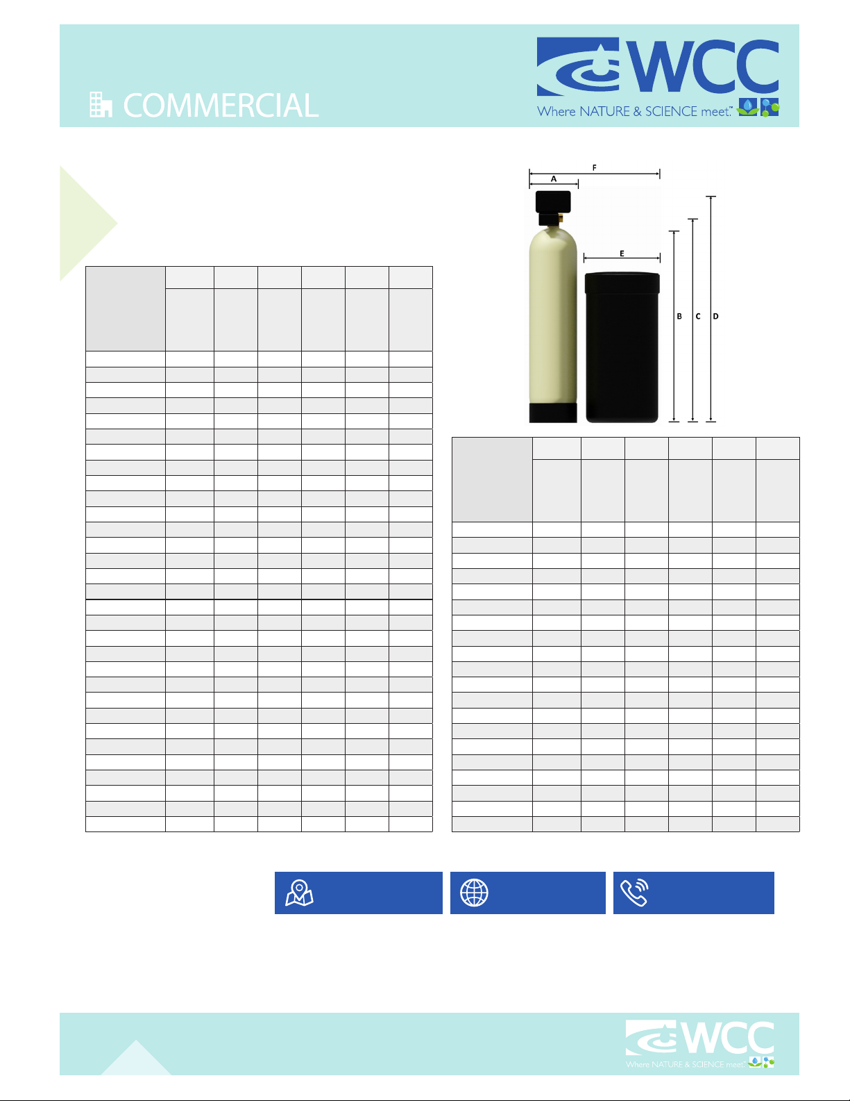
SPECIFICATIONS
All dimensions are approximate and subject to change without notice. Please consult our technical department for additional system information.
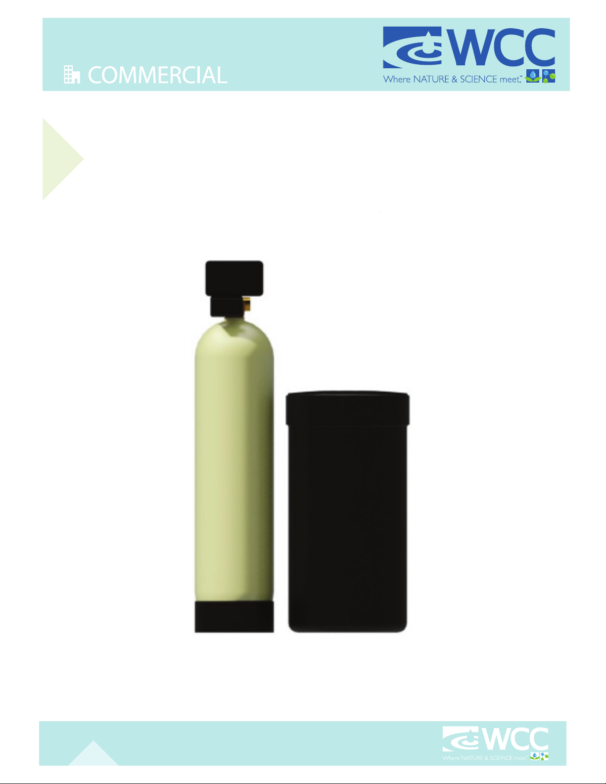
Single
Tank (MR) Models
WATER SOFTENER DIMENSIONS
Model
Series
Number
(A) (B) (C) (D) (E) (F)
Resin Tank
Diameter
(+/-0.5 in)
Resin Tank
Height
(+/-1 in)
Inlet/
Outlet
Height
(in)
Overall
Height
(in)
Brine Tank
Diameter
(in)
Overall
Length
(in)
EF-30-MR 10.0 44.6 46.0 53.0 18.0 32.0
EF-48-MR 10.0 47.7 54.0 56.0 18.0 32.0
EF-60-MR 12.0 53.4 55.0 61.0 18.0 34.0
EF-90-MR 14.0 66.1 68.0 74.0 24.0 42.0
EF-120-MR 16.0 66.2 68.0 74.0 24.0 44.0
EF-150-MR 16.0 66.2 68.0 74.0 24.0 44.0
EF-150X-MR 18.0 67.0 69.0 75.0 24.0 46.0
EF-180-MR 21.0 67.0 69.0 75.0 24.0 49.0
XF-30-MR 10.0 44.6 46.0 53.0 18.0 32.0
XF-48-MR 10.0 47.7 54.0 56.0 18.0 32.0
XF-60-MR 12.0 53.4 55.0 61.0 18.0 34.0
XF-90-MR 14.0 66.1 68.0 74.0 24.0 44.0
XF-120-MR 16.0 66.2 68.0 74.0 24.0 44.0
XF-150-MR 16.0 66.2 68.0 74.0 24.0 44.0
XF-150X-MR 18.0 67.0 69.0 75.0 24.0 46.0
XF-180-MR 21.0 67.0 69.0 75.0 24.0 49.0
SF-30-MR 10.0 47.7 50.0 54.0 18.0 32.0
SF-48-MR 12.0 53.4 55.0 60.0 18.0 34.0
SF-60-MR 12.0 53.4 55.0 60.0 18.0 34.0
SF-90-MR 14.0 66.1 68.0 73.0 24.0 42.0
SF-120-MR 16.0 66.2 68.0 73.0 24.0 44.0
SF-150-MR 16.0 66.2 68.0 73.0 24.0 44.0
MF-48-MR 12.0 53.4 55.0 60.0 18.0 34.0
MF-60-MR 12.0 53.4 55.0 60.0 18.0 34.0
MF-90-MR 14.0 66.1 68.0 73.0 24.0 44.0
MF-120-MR 16.0 66.2 68.0 73.0 24.0 44.0
MF-150-MR 16.0 66.2 68.0 73.0 24.0 44.0
MF-180-MR 21.0 67.0 69.0 74.0 24.0 49.0
MF-210-MR 21.0 67.0 69.0 74.0 24.0 49.0
MF-240-MR 24.0 74.2 76.0 81.0 24.0 52.0
MF-300-MR 24.0 74.2 76.0 81.0 24.0 52.0
Model
Series
Number
(con’t)
(A) (B) (C) (D) (E) (F)
Resin Tank
Diameter
(+/-0.5 in)
Resin Tank
Height
(+/-1 in)
Inlet/
Outlet
Height
(in)
Overall
Height
(in)
Brine Tank
Diameter
(in)
Overall
Length
(in)
LF-90-MR 14.0 66.1 68.0 78.0 24.0 42.0
LF-120-MR 16.0 66.2 68.0 78.0 24.0 44.0
LF-150-MR 16.0 66.2 68.0 78.0 24.0 44.0
LF-150X-MR 18.0 67.0 69.0 79.0 24.0 46.0
LF-180-MR 21.0 67.0 69.0 79.0 24.0 49.0
LF-210-MR 21.0 67.0 69.0 79.0 24.0 49.0
LF-240-MR 24.0 74.2 76.0 86.0 24.0 52.0
LF-300-MR 24.0 74.2 76.0 86.0 24.0 52.0
LF-360-MR 30.0 78.9 81.0 91.0 30.0 64.0
LF-450-MR 30.0 78.9 81.0 91.0 30.0 64.0
LF-600-MR 36.0 80.4 83.0 92.0 39.0 79.0
HF-300-MR 24.0 77.0 82.0 92.0 24.0 52.0
HF-450-MR 30.0 79.7 85.0 95.0 30.0 64.0
HF-480-MR 30.0 79.7 85.0 95.0 30.0 64.0
HF-600-MR 36.0 82.3 87.0 97.0 39.0 79.0
HF-810-MR 42.0 72.5 78.0 88.0 39.0 85.0
HF-900-MR 42.0 72.5 78.0 88.0 50.0 96.0
HF-990-MR 48.0 72.5 87.0 97.0 50.0 102.0
HF-1200-MR 48.0 72.5 87.0 97.0 50.0 102.0
HF-1800-MR 63.0 86.0 104.0 114.0 50.0 117.0
We look forward to working with you!
Go to www.watercontrolinc.com, where
you’ll nd detailed product specication
info and application design questionnaires.
VISIT US ONLINE
Call 1-866-405-1268 or email
SPEAK DIRECTLY WITH ONE OF
WCC’S DESIGN ENGINEERS
To nd your authorized WCC representative,
please visit: www.watercontrolinc.com/
representative-locator/.
CONTACT YOUR LOCAL
SALES REPRESENTATIVE
WC-SNG © Water Control Corporation 0822