WDT GRANUDOS Flex-CPR Touch XL User manual

OI No.: BA SW 022-01 Granudos Flex Dosiereinheit EN.docx Language: EN
Operating Instructions
GRANUDOS Flex Dosing Unit
Operating Instructions Part 1, (without control unit)
for:
GRANUDOS Flex-CPR Touch XL
GRANUDOS Flex-Touch
GRANUDOS Flex-S5

Dosing unit GRANUDOS Type Flex-CPR Touch XL,
Type Flex-Touch and Type Flex-S5
Index: 00 Change date: 11/10/2023 OI No.: BA SW 022-01 Granudos Flex Dosiereinheit EN.docx Page 2 of 68
Table of contents
1About these instructions / general ..........................................................................................4
1.1 Scope of applicability.............................................................................................................4
1.2 Target group ..........................................................................................................................4
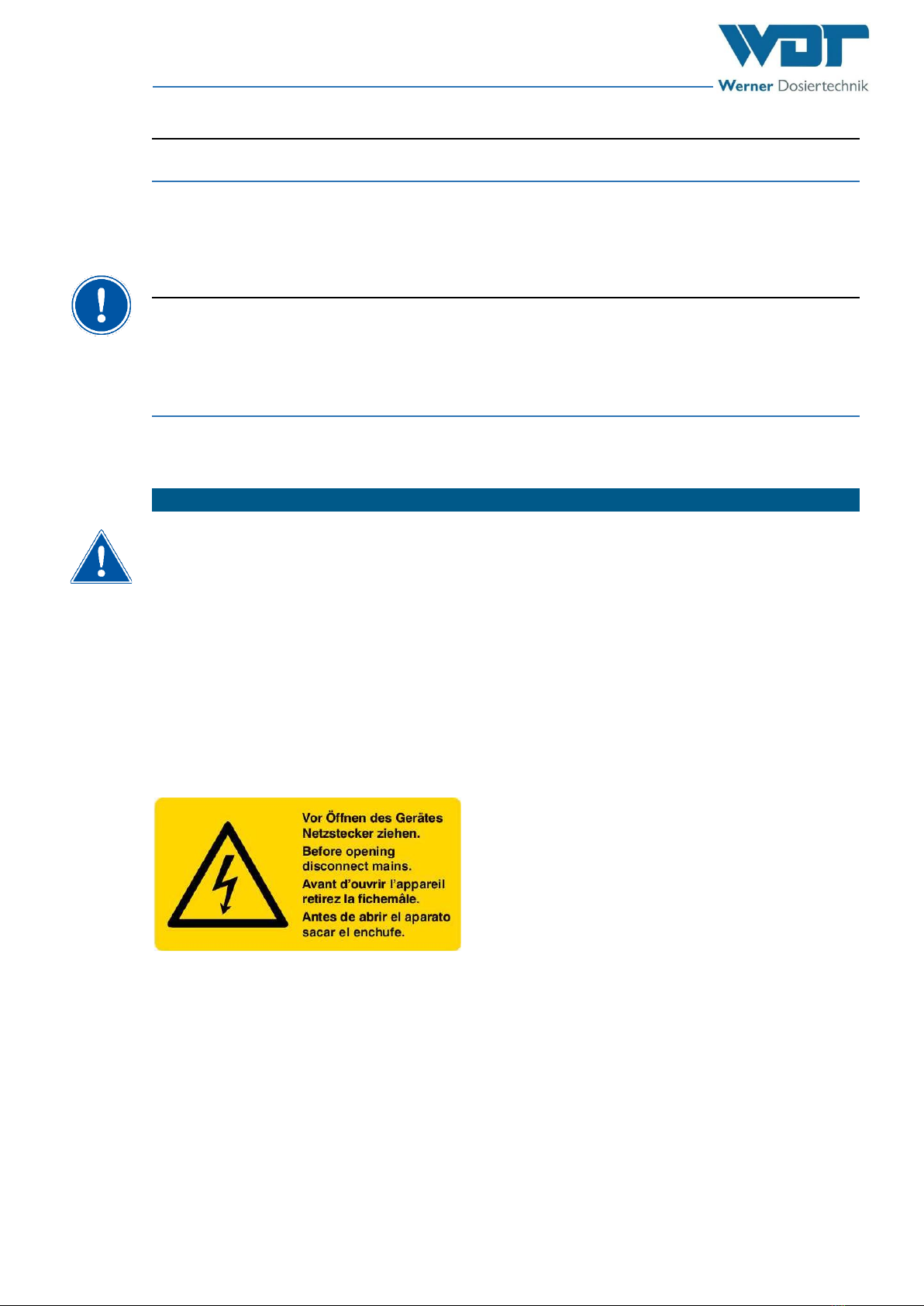
1.3 Symbols used .........................................................................................................................4
1.4 Warranty................................................................................................................................5
1.4.1 General terms and conditions of warranty............................................................................5
1.5 Additional information ..........................................................................................................6
1.6 Information regarding support queries.................................................................................6
2Safety.....................................................................................................................................7
2.1 Intended use..........................................................................................................................7
2.2 Safety notices.........................................................................................................................7
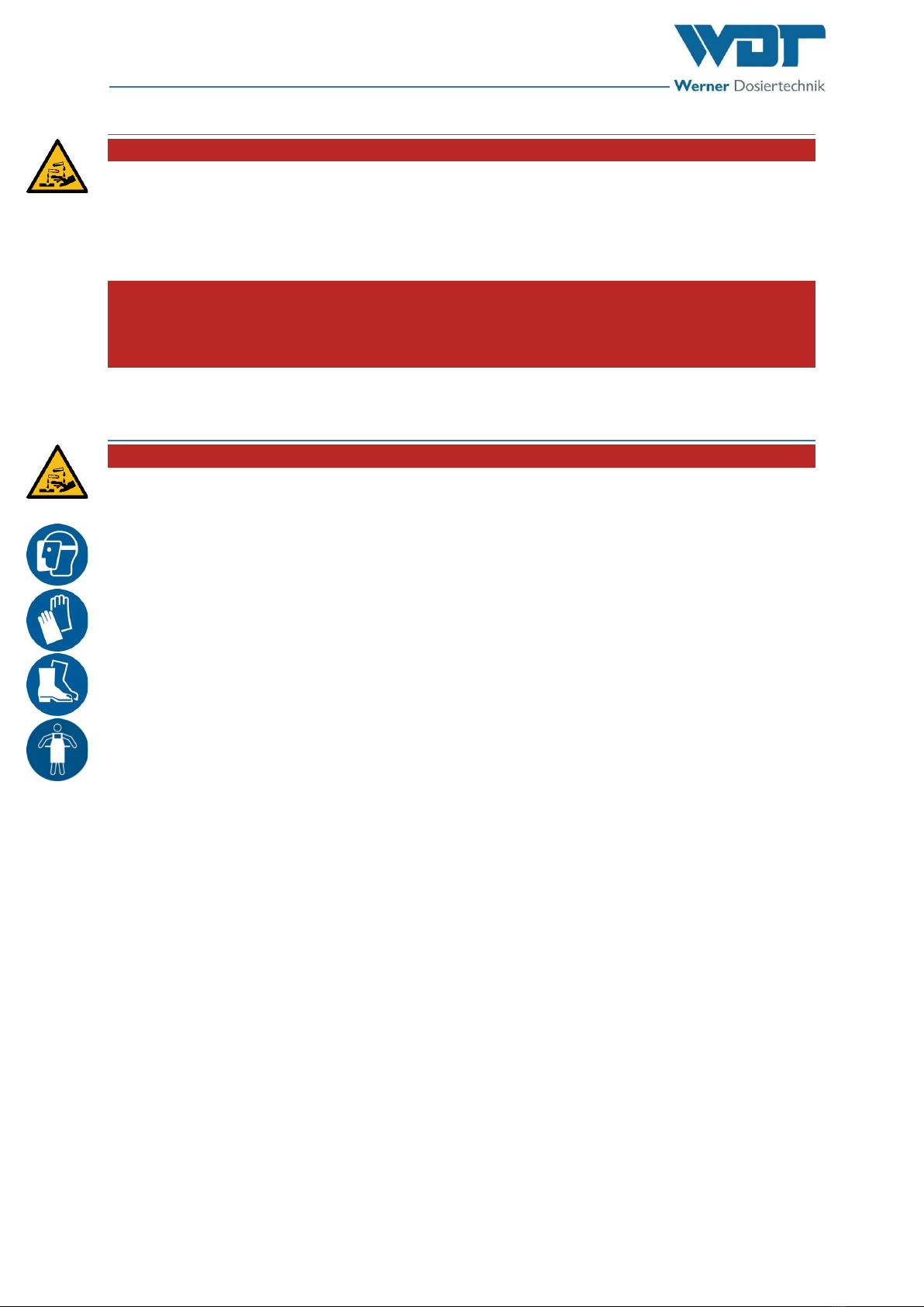
2.2.1 Handling of chemicals, risks to humans and the environment .............................................8
2.2.2 Protective measures and rules of conduct............................................................................8
3Product description –Functional description –Scope of delivery .............................................9
3.1.1 Scope of delivery / accessories..............................................................................................9
3.2 Product description ...............................................................................................................9
3.2.1 Functional description of the overall system.........................................................................9
3.2.2 Plastic housing with built-in components (standard)..........................................................12
3.2.3 Chlorine dosing (standard) ..................................................................................................14
3.2.4 Dissolving unit (standard)....................................................................................................15
3.2.5 Acid dosing (standard).........................................................................................................18
3.2.6 Flocculant dosing (option), (only CPR Touch XL) .................................................................18
3.2.7 Dust extraction (option).......................................................................................................19
3.2.8 Buffer tank with/without collecting tub (only for CPR Touch XL and Touch) (option)........20
3.2.9 Filling appliance (option) .....................................................................................................21
3.2.10 GRANUDOS control unit ......................................................................................................21
3.3 Identification of the device/ Identification plate.................................................................22
3.4 Technical data......................................................................................................................23
3.4.1 Requirements for the calcium hypochlorite granulate........................................................25
3.5 Transport and storage .........................................................................................................25
3.5.1 General notices, a separate position for the warning notice? ............................................25
3.5.2 Storage of chemicals............................................................................................................25
4Installation...........................................................................................................................26
4.1 Select the installation site....................................................................................................26
4.2 Installation instructions / installation suggestion................................................................26
4.2.1 Suggested installation..........................................................................................................27
4.3 Mechanical installation........................................................................................................28
4.3.1 GRANUDOS Flex installation................................................................................................28
4.3.2 Buffer tank installation ........................................................................................................28
4.4 Hydraulic installation...........................................................................................................28
4.4.1 Installation of the dissolving and measuring water supply .................................................31
4.4.2 Installation of the dosing line for the chlorine solution ......................................................34
4.4.3 Buffer tank installation (option) ..........................................................................................34
4.4.4 Installation of the overflow line for the flushing tub, collecting tub and dirt filter flushing
function...........................................................................................................................................34
4.4.5 Flocculant dosing (only CPR Touch XL)................................................................................34
4.5 Electrical installation............................................................................................................35
4.5.1 Opening and closing the housing, control unit CPR Touch XL and Touch...........................35
4.5.2 Opening and closing the housing, control unit S5...............................................................36
4.5.3 Electrical connection............................................................................................................36
5Commissioning/ recommissioning.........................................................................................38
5.1 Safety notices.......................................................................................................................38

Dosing unit GRANUDOS Type Flex-CPR Touch XL,
Type Flex-Touch and Type Flex-S5
Index: 01 Change date: 11/10/2023 OI No.: BA SW 022-01 Granudos Flex Dosiereinheit EN.docx Page 3 of 68
5.2 Commissioning ....................................................................................................................38
5.2.1 Inserting/replacing the peristaltic pump’s roller carriers ...................................................38
5.2.2 Preparing acid dosing for operation....................................................................................40
5.2.3 Preparing flocculant dosing for operation (only CPR Touch XL).........................................40
5.2.4 Filling the dosing hopper with chlorine granulate ..............................................................41
5.2.5 Venting of the booster pump and the piping to the GRANUDOS .......................................45
5.2.6 Venting the dust extraction pump (option) ........................................................................46
5.2.7 Setting the water flow in the dissolving unit and the pressure switch...............................47
5.2.8 Setting the water level in the flushing tub ..........................................................................49
6Operation / Use ................................................................................................................... 50
6.1 Replenish consumables .......................................................................................................50
6.2 Operation of the control unit ..............................................................................................50
7Maintenance / Care / Fault removal ..................................................................................... 51
7.1 Device maintenance ............................................................................................................51
7.1.1 Cleaning the dirt filter..........................................................................................................51
7.1.2 Replacing the dosing screw and the dust gasket.................................................................52
7.1.3 Injector with flow switch, replacing the hole washer .........................................................56
7.1.4 Setting the chlorine empty switch at the dosing hopper (option)......................................57
7.1.5 Replacing the dosing hose of the peristaltic pumps (acid or flocculation) .........................57
7.1.6 Cleaning the dust extraction (option)..................................................................................59
7.2 Fault removal.......................................................................................................................60
8Decommissioning –Storage –Disposal ................................................................................. 61
8.1 General ................................................................................................................................61
8.2 Decommissioning of the GRANUDOS Flex dosing device....................................................61
8.3 Decommissioning of the buffer tank (option).....................................................................61
8.4 Disposal of used parts and operating materials..................................................................61
9Documents .......................................................................................................................... 62
9.1 Declaration of conformity ...................................................................................................62
9.2 Wiring diagrams...................................................................................................................63
9.3 Commissioning protocol......................................................................................................64
9.4 Operation data sheet...........................................................................................................65
9.5 Maintenance protocol.........................................................................................................66
9.6 Spare parts list, wear parts list ............................................................................................67
10 Appendices .......................................................................................................................... 68
Reproduction of any kind and translation into other languages, even in excerpts, is only permitted with
the express authorisation of the company WDT - Werner Dosiertechnik GmbH & Co. KG.
Subject to technical modifications.
These operating instructions are an English translation of the original German version by the company
WDT.
Responsible for the content:
WDT - Werner Dosiertechnik GmbH & Co. KG
Hettlinger Str. 17
D-86637 Wertingen-Geratshofen
Phone: +49 (0) 82 72 / 9 86 97 –0
Fax: +49 (0) 82 72 / 9 86 97 –19
Web: https://werner-dosiertechnik.de
Mail: info@werner-dosiertechnik.de

Dosing unit GRANUDOS Type Flex-CPR Touch XL,
Type Flex-Touch and Type Flex-S5
Index: 01 Change date: 11/10/2023 OI No.: BA SW 022-01 Granudos Flex Dosiereinheit EN.docx Page 4 of 68
1About these instructions / general
1.1 Scope of applicability
These instructions describe the function, installation, commissioning and operation of the GRANUDOS
Flex-CPR Touch XL, Flex-Touch and Flex-S5 dosing device along with the corresponding accessories.
The Operating Instructions must be read carefully before use and kept on the device for direct use!
These Operating Instructions are valid in conjunction with the Operating Instructions:
“CPR-Touch XL Measuring and Control Unit” No. BA MR 001 or
“GRANUDOS Touch Control Unit” No. BA SW 010 or
“GRANUDOS S5 Control Unit” No. BA SW 014.
1.2 Target group
Only our instructed partners and people who have been trained in the device functions are permitted
to work on the system, provided that they have read and understood these Operating Instructions.
Electrical connection work may only be carried out by appropriately trained specialists!
1.3 Symbols used
This document uses the following types of safety notices as well as general notices:
DANGER!
“DANGER” denotes a safety notice which, if disregarded, will lead to serious or life-threat-
ening injuries or death!
DANGER DUE TO CORROSIVE SUBSTANCES!
This safety notice denotes risks which, if disregarded when handling chemicals, will lead to
serious or life-threatening injuries or death!
WARNING!
“Warning” denotes a safety notice which, if disregarded, may lead to serious or life-threat-
ening injuries or death!
CAUTION!
“Caution” denotes a safety notice which, if disregarded, may lead to injuries!
ATTENTION!
“ATTENTION” denotes a safety notice which, if disregarded, may lead to material damage
or may impair the function of the system!
ATTENTION! ESD SENSITIVE COMPONENTS!
“ESD SENSITIVE” denotes electronic components that may be damaged by electrostatic dis-
charges.
The generally accepted safety precautions for electronic components must be observed
when handling the devices!

Dosing unit GRANUDOS Type Flex-CPR Touch XL,
Type Flex-Touch and Type Flex-S5
Index: 01 Change date: 11/10/2023 OI No.: BA SW 022-01 Granudos Flex Dosiereinheit EN.docx Page 5 of 68
NOTICE!
A “NOTICE” denotes information that is of particular importance for the smooth running of opera-
tions and that can disrupt the operating process if not observed.
TIP!
A “TIP” denotes information that may result in improvements in the operating process.
USE FACE PROTECTION!
Wear approved face protection to prevent facial injuries due to contact with hot or chemical materi-
als.
USE HAND PROTECTION!
Wear approved hand protection to prevent hand injuries due to contact with hot or chemical materi-
als (according to DIN EN 374: Protective gloves against dangerous chemicals and micro-organisms).
USE PROTECTIVE APRON!
Wear an approved protective apron to prevent injuries to the front of your body due to contact with
hot or chemical materials.
USE FOOT PROTECTION!
Wear approved foot protection to prevent foot injuries due to contact with hot or chemical materials
or falling objects.
1.4 Warranty
All WDT devices and systems are manufactured using modern production methods and are subject to
comprehensive quality control. However, should there be a reason for complaint, any compensation
claims shall be directed to the company WDT in accordance with the general terms and conditions of
warranty.
1.4.1 General terms and conditions of warranty
The company WDT assumes a 2-year warranty, starting with the commissioning, up to 27 months after
delivery; subject to correct installation and commissioning with a completed and signed commission-
ing protocol.
Exempt from this are wear parts such as seals, hoses, diaphragms, dosing screws, electrodes, roller
carriers and other parts that are subject to mechanical or chemical wear and tear. For these we assume
a warranty of 1/2 year.

Dosing unit GRANUDOS Type Flex-CPR Touch XL,
Type Flex-Touch and Type Flex-S5
Index: 01 Change date: 11/10/2023 OI No.: BA SW 022-01 Granudos Flex Dosiereinheit EN.docx Page 6 of 68
Our enterprise resource planning system requires an invoice for each delivery (including warranty ser-
vices). When returning a defective component, upon review you will receive a corresponding credit, if
applicable. We request a return within 14 days.
The costs for subsequent damage and for the processing of warranty claims are excluded.
There are no warranty claims for damage caused by frost, water or electrical overvoltage or by im-
proper handling.
NOTICE!
In order to protect the warranty claims, please mail the completed commissioning protocol, along
with the defective component, to the company WDT.
Without the commissioning protocol, we reserve the right to an exclusion of warranty.
CAUTION!
In the event of any unauthorised modifications to the device, the warranty and product lia-
bility will be voided!
1.5 Additional information
Additional information concerning specific topics, such as design of the dosing performance or descrip-
tion of the operating parameters, may be obtained from your specialist dealer, or directly from:
WDT - Werner Dosiertechnik GmbH & Co. KG
Hettlinger Str. 17
D-86637 Wertingen-Geratshofen
Phone: +49 (0) 82 72 / 9 86 97 –0
Fax: +49 (0) 82 72 / 9 86 97 –19
Web: https://werner-dosiertechnik.de
Mail: info@werner-dosiertechnik.de
1.6 Information regarding support queries
The GRANUDOS Flex series’ control unit is subject to continued further development of both its firm-
ware and hardware. We always strive to preserve the compatibility of the components used.
For spare part orders, we require the following data. You can find these on the identification plate.
device designation
device serial number
year of manufacture
In addition, we require the following data for technical support queries. These are located in the menu
item MenuServiceInfo.
current DSP version
current I/O version
current http version

Dosing unit GRANUDOS Type Flex-CPR Touch XL,
Type Flex-Touch and Type Flex-S5
Index: 01 Change date: 11/10/2023 OI No.: BA SW 022-01 Granudos Flex Dosiereinheit EN.docx Page 7 of 68
2Safety
2.1 Intended use
The GRANUDOS Flex dosing device and the buffer tank may only be used for the disinfection of swim-
ming pool water with calcium hypochlorite.
Also pay attention to the locally applicable regulations concerning accident prevention, occupational
safety and drinking water protection!
NOTICE!
The Granudos standard booster pump (BP) is not suitable for saline water (seawater/brine pools).
A special version is available for this case. Pay attention to this when placing your order!
2.2 Safety notices
Carefully read and pay attention to the operating instructions prior to installation and use of the de-
vice!
Work on the device and changes in the settings may only be carried out by properly instructed persons!
ATTENTION!
Remote access by non-authorised persons possible!
The GRANUDOS Flex control unit makes remote display possible using network-enabled de-
vices.
The operator is responsible for ensuring that only authorised persons can access the
device!
The operator, or their authorised representative, is further responsible for the safety
of all Internet or WLAN connections!
Pay attention to the warning notices on the device

Dosing unit GRANUDOS Type Flex-CPR Touch XL,
Type Flex-Touch and Type Flex-S5
Index: 01 Change date: 11/10/2023 OI No.: BA SW 022-01 Granudos Flex Dosiereinheit EN.docx Page 8 of 68
2.2.1 Handling of chemicals, risks to humans and the environment
DANGER DUE TO CORROSIVE SUBSTANCES!
Formation of substances hazardous to health when handling and mixing chemicals!
In emergencies, contact the respective poison control centre.
EMERGENCY NUMBER:
MUNICH EMERGENCY POISON CENTRE (OR ANY OTHER POISON CENTRE)
PHONE: +49 89 19240
2.2.2 Protective measures and rules of conduct
DANGER DUE TO CORROSIVE SUBSTANCES!
Development of chlorine gas when mixing chemicals!
The GRANUDOS Flex dosing system doses both the calcium hypochlorite granulate and the
pH-reducer (acid) from the delivery container. These substances have a strong reaction
when combined and release toxic chlorine gas outside of water.
For this reason, the greatest possible care is required when working with these
chemicals!
Wearing personal protective equipment is essential: Face protection, protective
gloves, protective apron, foot protection.
The chlorine granulate and the acid must not be mixed with each other or with other
chemicals or substances!
Store chemicals in such a way that they are not accessible to unauthorised persons.
When storing chemicals, pay attention to the chemical manufacturers’ safety data
sheets!

Dosing unit GRANUDOS Type Flex-CPR Touch XL,
Type Flex-Touch and Type Flex-S5
Index: 01 Change date: 11/10/2023 OI No.: BA SW 022-01 Granudos Flex Dosiereinheit EN.docx Page 9 of 68
3Product description –Functional description –Scope of delivery
3.1.1 Scope of delivery / accessories
The scope of delivery includes the “GRANUDOS Flex” dosing system, which consists of the following
components:
Housing made of rotationally sintered PE in light grey
Dosing appliance for chlorine granulate
Dosing appliance for acid
Dissolving unit for chlorine and acid (with dust protection housing)
Dosing appliance for flocculant (only CPR Touch XL)
The following options are available for the dosing system
GRANUDOS collecting tub
Dosing hopper 15 kg
Filling appliance for various 10 kg buckets
Front cover for measuring cell block (only CPR Touch XL)
Dust extraction
Buffer tank with collecting tub (not for Flex-S5)
Flushing function at the dirt filter
3.2 Product description
The GRANUDOS dosing system is used for the disinfection of swimming pool water with calcium hypo-
chlorite.
3.2.1 Functional description of the overall system
The GRANUDOS Flex represents a dosing device for dosing calcium hypochlorite granulate. The chem-
ical is dissolved and fed into the pipe by means of a booster pump (BP) via an injector. The acid dosing
required for pH regulation of the swimming pool water is integrated and organised via the software
and a relay system in such a way that a joint dosing of chlorine and acid is excluded. The GRANUDOS
Flex dosing device is particularly well-suited for swimming pools with a water volume between 50 and
400 m³.
The functions of the GRANUDOS Flex-CPR Touch XL
Measuring of free chlorine with open measuring cell potentiostatic, pH value, redox potential and
temperature
Controlling the chlorine dosing using the measured value for free chlorine or for redox potential.
Dosing of chlorine granulate from the dosing hopper using the dosing screw and the knocker
Dosing of acid (pH-reducer) from the delivery container using a peristaltic pump
Dosing of flocculant from the delivery container using a peristaltic pump
Filling a buffer tank with chlorine solution for disinfecting additional small pools using dosing pumps
(option)
The functions of the GRANUDOS Flex-Touch
Dosing of chlorine granulate from the dosing hopper using the dosing screw and the knocker
Dosing of acid (pH-reducer) from the delivery container using a peristaltic pump
Filling a buffer tank with chlorine solution for disinfecting additional small pools using dosing pumps
(option)
The functions of the GRANUDOS Flex-S5
Dosing of chlorine granulate from the dosing hopper using the dosing screw and the knocker
Dosing of acid (pH-reducer) from the delivery container using a peristaltic pump

Dosing unit GRANUDOS Type Flex-CPR Touch XL,
Type Flex-Touch and Type Flex-S5
Index: 01 Change date: 11/10/2023 OI No.: BA SW 022-01 Granudos Flex Dosiereinheit EN.docx Page 10 of 68
Figure 1: Flow diagram GRANUDOS Flex Touch and Flex S5, without buffer tank
Figure 2: Flow diagram GRANUDOS Flex Touch with buffer tank
2
3
Measuring and con-
trolling
Central
control unit
Swimming pool
Filter
Overflow
pool
Heat ex-
changer
Dosing line
Acid
Water removal and
dosing connection:
Sleeve ¾”, piping: d25
Dosing system for
calcium hypochlorite
Intake pipe
Flow pressure < 0.2 bar
Circulation
pump
Overflow
pool
Dosing line
Circulation
pump
Overflow
pool
Heat ex-
changer
Overflow
pool
Circulation
pump
Heat ex-
changer
Filter
Central
control
unit
Intake pipe
Flow pressure > 0.2
bar
Measuring and
controlling
Measuring and
controlling
Control unit for
level switch
Acid
Dosing system for
calcium hypochlorite
Solenoid valve opens
when container empty
–GRANUDOS doses
with a high dosing per-
formance until the
container is full - ap-
prox. 10 minutes. No
dosing to the main
pool during this time.
Dosing station for
pH-reducer
Dosing station for
chlorine solution
Water removal and dosing connection:
Sleeve ¾“, piping d25
Additional pools
possible
Notice:
As a standard, the GRANUDOS is in-
stalled below the pool level.
When the GRANUDOS is installed
above the pool level, non-return
valves must be provided in the dos-
ing and inlet lines.
Filter
2
3

Dosing unit GRANUDOS Type Flex-CPR Touch XL,
Type Flex-Touch and Type Flex-S5
Index: 01 Change date: 11/10/2023 OI No.: BA SW 022-01 Granudos Flex Dosiereinheit EN.docx Page 11 of 68
Figure 3: Flow diagram GRANUDOS Flex CPR Touch XL without buffer tank
Figure 4: Flow diagram GRANUDOS Flex CPR Touch XL with buffer tank
1
1
Circula-
tion
pump
pH minus
Floccula-
tion
Swimming pool
Filter
Overflow
pool
Heat ex-
changer
Additional pools
possible
Acid
Dosing station for
pH-reducer
Buffer tank for
chlorine solution
Measuring and controlling
Circulation
pump
Control unit for
level switch
Measuring
water pump
MZ = Measuring cell block
pH minus
Flocculation
Notice:
As a standard, the GRANUDOS is in-
stalled below the pool level.
When the GRANUDOS is installed
above the pool level, non-return
valves must be provided in the dos-
ing and inlet lines.
MZ = Measuring cell block
Safety shut-down
Acid
Circulation
pump
Swimming pool
Filter
Overflow
pool
Heat ex-
changer
Dosing line
Flocculation
Water removal and dosing
connection:
Sleeve ¾”, piping: d25
Dosing system for
calcium hypochlorite
Intake pipe
Flow pressure < 0.2 bar
Central con-
trol unit
Swimming pool
Filter
Overflow
pool
Heat ex-
changer
Dosing line
Flocculation
Water removal and
dosing connection:
Sleeve ¾”, piping: d25
Dosing system for
calcium hypochlorite
Intake pipe
Flow pressure < 0.2 bar
Circulation
pump
Dosing line
Central con-
trol unit
Safety shut-down
Control valve on
the GRANUDOS
Pressurised air

Dosing unit GRANUDOS Type Flex-CPR Touch XL,
Type Flex-Touch and Type Flex-S5
Index: 01 Change date: 11/10/2023 OI No.: BA SW 022-01 Granudos Flex Dosiereinheit EN.docx Page 12 of 68
3.2.2 Plastic housing with built-in components (standard)
Overview GRANUDOS Flex-CPR Touch XL and Flex-Touch dosing devices
Figure 5: GRANUDOS Flex-CPR Touch XL and Flex-Touch with filling appliance
Key
01. Control unit
02. Main switch
03. Measuring cell block (only CPR Touch XL)
04. Bracket for redox test cylinder (only CPR Touch XL)
05. Ball valve inlet
06. Suction lance for pH-reducer (acid)
07. Housing
08. Collecting tub with drain (option)
09. Filling appliance (option)
10. Dosing hopper with lid
11. Dosing pump for pH-reducer (acid)
12. Dosing pump for flocculant (only CPR Touch XL)
13. Dosing unit for chlorine
14. Dissolving and flushing unit for chlorine granulate
15. Suction lance for flocculant (covered) (option)
16. Outflow to swimming pool
17. Manometer connection inlet
18. Manometer connection outflow
19. Flushing ball valve dirt filter
20. ---
12
13
14
11
16
10
15
09
18
17
02
03
04
05
06
01
08
07
19

Dosing unit GRANUDOS Type Flex-CPR Touch XL,
Type Flex-Touch and Type Flex-S5
Index: 01 Change date: 11/10/2023 OI No.: BA SW 022-01 Granudos Flex Dosiereinheit EN.docx Page 13 of 68
Overview GRANUDOS Flex-S5 dosing device:
Figure 6: GRANUDOS Flex-S5
Description
The attractive housing (07)is sintered in one piece from light grey PE and is therefore extraordinarily
stable. The dosing hopper (10) with a filling capacity of 5 or 15 kg is inserted into the housing from
above and can thus be easily removed, e.g., for maintenance work. An optional filling appliance (09)is
available, which allows a chlorine bucket to be placed on top. The dosing unit (13), consisting of a
dosing motor with dosing screw and heated downpipe, is screwed into the bottom of the dosing hop-
per. The control unit (01) rests on top of the housing. The dosing hopper is protected against splashing
water by a transparent lid. The bottom of the housing contains the dissolving and flushing unit (14) for
the chlorine granulate.
13
14
11
16
10
15
18
17
08
02
05
06
01
07
19

Dosing unit GRANUDOS Type Flex-CPR Touch XL,
Type Flex-Touch and Type Flex-S5
Index: 01 Change date: 11/10/2023 OI No.: BA SW 022-01 Granudos Flex Dosiereinheit EN.docx Page 14 of 68
3.2.3 Chlorine dosing (standard)
Overview chlorine dosing
Figure 7: Dosing hopper 5 kg (standard) Dosing hopper 15 kg (option)
Key
Description
The chlorine dosing is controlled in alternating cycles with the acid and is monitored.
The illustrated dosing hopper (10) is attached inside the plastic housing and is used to dose the chlorine
granulate into the dissolving and flushing unit (14).
The dosing appliance consists of the dosing hopper (10) with a capacity of approximately 5 kg or 15 kg
and the dosing unit, which comprises the dosing motor (23) with flange, the dosing screw (27), the
motor bracket (24) and the heated dosing pipe (28).
The heating of the dosing pipe prevents the condensation of water vapour, which could lead to a dos-
ing blockage. The dosing unit is screwed into the bottom of the dosing hopper.
The dosing hopper is either closed tightly with the lid, or the filling appliance is used. With the filling
appliance, a chlorine bucket can be placed directly on the dosing hopper, see Figure 5.
For maintenance work on the dosing, the dosing appliance is completely removed from the housing by
lifting it upwards.
The dosing screw (27) transports the calcium hypochlorite granulate from the dosing hopper into the
flushing pipe (38) of the underlying dissolving unit. A solenoid knocker (25) is installed for breaking up
the chlorine granulate; during each dosing process, the solenoid knocker delivers a short blow to the
dosing hopper, thus preventing the granulate from bridging across the dosing screw.
10. Dosing hopper with lid
---
22. Chlorine empty switch (option)
23. Dosing motor
24. Motor bracket
25. Solenoid knocker (with connection socket)
26. Cleaning plug
27. Dosing screw (not visible)
28. Dosing pipe (with heater)
29. ---
10
22
2
23
24
4
25
8
26
9
27
28
10
22
2
23
24
4
25
8
26
9
27
28
7

Dosing unit GRANUDOS Type Flex-CPR Touch XL,
Type Flex-Touch and Type Flex-S5
Index: 01 Change date: 11/10/2023 OI No.: BA SW 022-01 Granudos Flex Dosiereinheit EN.docx Page 15 of 68
3.2.4 Dissolving unit (standard)
Overview Type Flex-CPR Touch XL dissolving unit
Figure 8, GRANUDOS dissolving unit
Overview GRANUDOS Type Flex-Touch and Type Flex-S5 dissolving units
Figure 9, GRANUDOS dissolving unit
41
42
43
40
44
39
31
32
33
35
36
34
38
45
45
41
42
43
40
44
39
31
35
36
34
38

Dosing unit GRANUDOS Type Flex-CPR Touch XL,
Type Flex-Touch and Type Flex-S5
Index: 01 Change date: 11/10/2023 OI No.: BA SW 022-01 Granudos Flex Dosiereinheit EN.docx Page 16 of 68
Overview flushing tub
Figure 10, GRANUDOS Flex flushing tub
Key dissolving unit/flushing tub
Description
The dissolving unit is installed on a base plate in the plastic housing and is used for the separate dis-
solving of the chemicals.
In the dissolving unit, the dissolving water originating from the swimming pool filter system is sepa-
rated downstream of the booster pump (36). A partial flow is directed to the injector. The other partial
flow is directed into the flushing tub (39)via the floating valve (47). From there, it is suctioned off by
the injector (40), together with the additional chemicals dosed in the flushing pipe (38). The chlorine
granulate and the pH-reducer (acid) are dosed in turns with intermittent breaks into the water flowing
through the flushing pipe. Approx. 50% of the chlorine granulate is dissolved in the injector, the re-
mainder is kept in circulation in the dissolving cyclone (44)until it also has been completely dissolved.
Shortly after the dosing has started, the chlorine granulate can be seen in the cyclone.
Changes in the dissolving unit’s water supply that cause the dissolving unit to no longer operate
properly are recorded by the level switch (48), the flow switch (42)and the pressure switch (31). In
these cases, the dosing of chemicals and also the booster pump, if applicable, will be turned off to
prevent potential subsequent damage. For detailed information, see the separate Operating Instruc-
tions for the control unit:
For GRANUDOS CPR Touch XL, Operating Instructions “CPR-Touch XL Measuring and Control
Unit” No. BA MR 001.
For GRANUDOS Touch, Operating Instructions “GRANUDOS Touch Control Unit” No. BA SW
010.
For GRANUDOS S5, Operating Instructions “GRANUDOS S5 Control Unit” No. BA SW 014.
31. Pressure switch
32. Pressure retention valve for supplying measuring cell
block (only CPR Touch XL)
33. Outflow for supplying the measuring cell
block (only CPR Touch XL)
34. Dirt filter d75 mm
35. Flushing connection for dirt filter
36. Booster pump; different designs
37. ---
38. Flushing pipe
39. Flushing tub
40. Injector
41. Pipe union with hole washer
42. Flow switch for suction pipe
43. Dosing valve for pH-reducer
44. Dissolving and mixing cyclone
45. Dust cover for booster pump
46. Flushing tub overflow
47. Floating valve inlet for flushing tub
48. Level switch min/max for flushing tub
49. Lid for flushing tub
50. ---
48
47
46
49

Dosing unit GRANUDOS Type Flex-CPR Touch XL,
Type Flex-Touch and Type Flex-S5
Index: 01 Change date: 11/10/2023 OI No.: BA SW 022-01 Granudos Flex Dosiereinheit EN.docx Page 17 of 68
The pressure switch, installed on the pressure side of the booster pump, switches off the GRANUDOS
in the event of a pressure drop or the intake of air to prevent the booster pump from running dry.
In addition, a control switch can be connected to turn off the dosing in the event of a fault in the
swimming pool filter system, e.g., no flow in the clean water line.
In case of water-MIN and pure water contact, the dosing and the booster pump are switched off.
In case of water-MAX, the dosing is stopped and the booster pump continues to run.
A flow switch (42) is installed in the injector’s suction line (40); this is of essential importance for the
GRANUDOS’s operational safety! If the injector’s suction capacity is too low, the switch body that has
been pushed upwards by the upward flow in the suction pipe, drops and the chemical dosing is turned
off. This ensures that dosing only occurs in vigorously flowing water and the two chemicals cannot
meet in the open area.
In the same way, the floating valve (47) blocks this inlet into the flushing tub in the event of a downtime
or malfunction of the device. However, these actions cannot guarantee an absolute separation from
the circulation circuit. If this is required, securely sealing shut-off valves must be installed in the inlet
and dosing lines; either non-return valves or self-closing pneumatic valves, depending on the pressure
situation. Pay attention to the pressure loss caused by the valves during operation.
The Flushing tub overflow (46)conducts the –nearly chlorine-free –excess water that occurs in case of
the “water-max” fault to the drain.
The pressure retention valve (32) (only for CPR Touch XL) is used to supply the measuring cell block
with a constant pressure and prevents the overflow of the flushing tub when no water is suctioned off.
The pressure retention valve is preset ex works; however, it may have to be adapted to the local con-
ditions during commissioning, if necessary.
To prevent the chlorine granulate and the acid from meeting and reacting with each other in the open
part of the dissolving unit, the following safety package has been installed:
The dosing of the two chemicals occurs in set cycles with pauses between the dosing processes.
The power supply of the two dosing motors is locked via a relay system in such a way that both
motors can never be running at the same time!
The water supply and water flow are monitored by the pressure switch (31), level switch (48) and
flow switch (42).
Dosing only takes place when the water flow is ensured.
In the event of deviation from the set target values (e.g., water-min/max, pressure flow, etc.) the
dosing system is turned off and a corresponding fault indication is displayed.
ATTENTION!
The use of sulphuric acid is generally possible up to a concentration of 50%. With higher
concentrations or when using other acids (e.g., hydrochloric acid, dissolved sodium hydro-
gen sulphate, etc.), pay attention to a change in dosing performance and/or increased cor-
rosiveness! We recommend consultation with the manufacturer!

Dosing unit GRANUDOS Type Flex-CPR Touch XL,
Type Flex-Touch and Type Flex-S5
Index: 01 Change date: 11/10/2023 OI No.: BA SW 022-01 Granudos Flex Dosiereinheit EN.docx Page 18 of 68
3.2.5 Acid dosing (standard)
Overview acid dosing
Description
The acid dosing in the GRANUDOS Flex is used to completely dis-
solve the chlorine granulate and to correct the pH value of the pool
water. For each kg of chlorine granulate, approx. 0.5-1 litres of 37%
sulphuric acid must be added. For this purpose, a peristaltic pump
(11, page12)is installed as standard. The acid dosing is controlled
automatically by the control unit.
Option with buffer tank:
For the filling of the buffer tank, the acid dosing must be adjusted.
During commissioning, the chlorine dosing must be adjusted so that
the chlorine solution in the buffer tank has a pH value between 6.8
and 7.2. In that case, the calcium hypochlorite solution is com-
pletely dissolved. The solution is practically clear and lacks a strong
chlorine odour. If the pH value is too low, the solution has a strong
chlorine odour and becomes more corrosive. If the pH value is too high, the solution is cloudy and
precipitation or deposits form in the buffer tank and in the dosing lines. The correct dosing ratio is set
by measuring the pH value. See the operating instructions for the respective control unit.
Peristaltic pumps are able to transport even the smallest dosing quantities reliably and evenly, even
when air or gas bubbles are trapped in the suction line. Rotating rollers press the dosing hose against
the housing wall, which pushes the liquid in the hose out in front of the rollers while simultaneously
suctioning again behind them. The peristaltic pump is exceptionally reliable and easy to operate.
The peristaltic pump sucks the acid from the acid canister through the suction lance (06, page 12). The
fill level in the acid canister is determined with a level switch for the empty indication.
As a rule, sulphuric acid with a concentration of 37% is used as a pH-reducer.
When using hydrochloric acid, attention should be paid to the proper concentration and material re-
sistance. For additional information, see the chapter Commissioning.
In solutions consisting of sodium hydrogen sulphite, the concentration must not be above 20% (approx.
equivalent to 10% sulphuric acid). It must be considered whether the pump’s circulation performance
is sufficient for neutralisation because the sodium hydrogen sulphate has a lower acid capacity than
sulphuric acid, for example.
3.2.6 Flocculant dosing (option), (only CPR Touch XL)
Overview flocculant dosing
Description
The flocculant is used to make the finest impurities from the
swimming pool water, which are not retained by the swimming
pool filter system, suitable for filtration.
The peristaltic pump (12, page 12)of the same design as for acid
dosing is used for flocculant dosing, but it is rotation speed con-
trolled and has a smaller hose diameter. The suction lance is
used to suck the flocculant from the flocculant canister. The fill
level in the canister is determined with a level switch for the
empty indication.
Figure 11: Acid pump
Figure 12: Flocculant dosing pump

Dosing unit GRANUDOS Type Flex-CPR Touch XL,
Type Flex-Touch and Type Flex-S5
Index: 01 Change date: 11/10/2023 OI No.: BA SW 022-01 Granudos Flex Dosiereinheit EN.docx Page 19 of 68
3.2.7 Dust extraction (option)
Overview dust extraction
Figure 13: Dust extraction
Key dust extraction
Description
The dust extraction is used to reduce the amount of dust entering the environment. The use of granu-
lates with a higher dust content may lead to a minor dust discharge at the device. This will subsequently
settle on the protective cover and in the housing’s interior. The dust extraction is based on the water
jet nozzle (injector) principle.
The flushing of the dust extraction is used for the automatic cleaning of the flushing pipe and the dust
extraction’s injector. During operation, it is possible that the chlorine dosing and the flushing are ac-
tive simultaneously. This constitutes a normal operating state.
The flushing interval is controlled via the control unit. This is preset ex works to 10 s flushing and 1 h
pause.
51. Dust extraction pump
52. Flushing water distributor
53. Solenoid valve dust extraction
54. Flushing ring assembly group
55. Injector dust extraction
56. Flushing pipe dust extraction assembly group
57. Drain connection
58. Suction hose
52
51
53
54
55
56
58
57

Dosing unit GRANUDOS Type Flex-CPR Touch XL,
Type Flex-Touch and Type Flex-S5
Index: 01 Change date: 11/10/2023 OI No.: BA SW 022-01 Granudos Flex Dosiereinheit EN.docx Page 20 of 68
3.2.8 Buffer tank with/without collecting tub (only for CPR Touch XL and Touch) (option)
Overview buffer tank Key buffer tank
Description
1. When the buffer tank’s lower control level “Start filling” is reached, the solenoid valve to the swim-
ming pool filter system closes and the solenoid valve for buffer tank filling opens. Buffer tank filling
starts.
2. At the buffer tank’s upper control level “Stop filling”, the filling is stopped. This is followed by a
flushing cycle to clean the dissolving unit: initially for 20 seconds with acid, followed by 20 seconds
with water only. Afterwards, the solenoid valves switch back to normal operation.
3. At the buffer tank’s “Minimum alarm” level, the dosing pump(s) are switched off. An alarm mes-
sage is shown on the display; the alarm output is active.
4. At the buffer tank’s “Maximum alarm” level, an alarm message is shown on the display. The dosing
pump(s) continue(s) running.
Contact positions
When the container is half full, the level switches’ contacts are set as follows:
Level position Contact
Maximum level alarm closed
Maximum level open
Minimum level alarm open
Minimum level open
An activated carbon filter (61)is screwed on top of the buffer tank. It is used to clean the chlorine-
containing air when filling the buffer tank and for venting and aerating.
The buffer tank is located in the collecting tub. An alarm switch (65)for leakages is installed in the
collecting tub.
61. Activated carbon filter
62. 4-fold level switch
a) Maximum level alarm;
b) Maximum level; stop filling
c) Minimum level; start filling
d) Minimum level alarm;
63. Buffer tank 300 l PE
64. Collecting tub buffer tank (not shown)
65. Alarm switch for collecting tub buffer tank,
(not shown)
Figure 14: Buffer tank
a)
61
63
62
b)
c)
d)
This manual suits for next models
2
Table of contents
Other WDT Laboratory Equipment manuals