Dynamics
UVD32OE
Installation
and
Maintenance
Manual
READ
AND
UNDERSTAND
ALL
INSTRUCTIONS BEFORE
INSTALLING
OR
USING
THIS
PRODUCT
PERFORMANCE
CONSIDERATIONS
The
performance
of
the
UVD320E
UV
disinfection
chamber
has
been
third
party
validated
using
accepted
bio-assay techniques.
The
UVD320E
is
equipped
with
both
visible
and
audio
lamp
failure
alarms.
For
your
safety,
it
is
necessary
that
you
determine
that
the
audio
alarm
can
be
heard
where
you use
the
water
treated
by
the
unit.
It
is
possible
to
operate the
unit with the
lamp
disconnected
which
will
allow
you
to
validate
the
adequacy of
the
audio
alarm
function
in
your
installation.
In
order
to
optimize
disinfection
performance,
you
must
only
use
the
unit with
water
that
meets the
minimum
standard
and
replace
the
UV
lamp
at
recommended
intervals. Failure
to
follow
these
guidelines
will
result
in
reduced
disinfection
performance.
UV
RADIATION
HAZARD
•
NEVER
OPERATE
UV
LAMP OUTSIDE
OF
THE
UV
•
DISINFECTION
CHAMBER
—
EXPOSURE
TO
UV
LIGHT
CAN
RESULT
IN
EXTREME
BURNING
OF
SKIN
AND
EYES
Safety
instructions
—
Please
read
carefully
/I\
Danger:
Do
not
plug
the
unit
in
if
any
of
the
external
surfaces or
electrical
parts
are
wet.
Condensation
on
the
disinfection
chamber
is
normal.
Danger:
To
avoid
possible electnc
shock,
special care should
be
taken
since
water
may
be
present
near
electrical equipment. Unless
referred
to
in
these
instructions,
do
not
attempt repairs
yourself.
Contact
the
manufacturer
for service
advice.
Danger:
Do
not
operate this
system
if
it
has
a
damaged
electrical
cord
or
plug,
is
malfunctioning,
or
has
been
dropped
or
damaged
in
any
way.
Caution:
Do
not
use
this
unit
for
anything
other
than
its intended
potable
water
application.
The
use
of attachments
not
recommended,
approved
or
sold
by
the
manufacturer/distributor
may
result
in
an
unsafe condition.
____
INSTALLATION
CAUTIONS
Connect your
UV
unit
to
a
grounded
(3
pronged)
receptacle
(120V,
60HZ)
(a
GFI
is
highly
recommended)
and
ensure
that
the
lamp
connector
ground
wire
is
connected
to
the
ground
stud
on
the
top
of
the
reactor
vessel.
Note:
Power
source
for
applications outside
of
North
America
must
match
requirements
of
the
unit
(eg.
240V,
50Hz).
OUV
Dynamics
disinfection devices
are
designed
to
be
installed
on
the
cold
water
line
only.
OThe
unit
must
be
installed
vertically
with the lamp
connector
pointing
upwards
—
the
water
source
should only
be
connected
to
the
inlet
port
on
the
bottom of
the
unit.
CAUTION:
reversing
the
flow
direction
by
connecting
the
water
source
to
the
side mounted
output
port
could result
in
reduced
disinfection performance.
Olnstall
your
UV
Dynamics
disinfection
system indoors
in a
protected
area where the
temperature
does
not
fall
below
4°C.
(40°F) and
the
humidity
level
is
low
(to
prevent
condensation
on
the
chamber). This
unit
functions
ideally
in
a
temperature
range
from
9°C
-
29°C.
(49—
85F)
OUse
teflon
tape
on
all
pipe connections.
DO
NOT
USE
ANY
OTHER SEALANT.
O
If
the
installation
location
is
subject
to
frequent
power
outages,
surges,
brown
out
conditions
or
electrical
storm
activity,
a
surge
protection
device
should
be
installed
on
the
AC
supply
to
prevent
damage
to
the power source.
O
Do
not
connect UVDynamics disinfection
systems
directly
to
PEX
tubing
or
other
plastic
piping.
Plastic
material
will
suffer
structural
degradation,
and
possible
service
failures, when subjected
to long-
term
UV
light
exposure.
PEX
tubing
and
plastic
piping
can
be
connected
directly
to
the
inlet
port
if
it
is
located
on
the
bottom
of
the
chamber. All
side ports
will
require
the
use
of
a
metallic
light
dam
(16”/4Ocm section
of
metallic
tubing, street elbow
or
stainless
steel
flex
connector
suitably
bent
to
prevent
direct
UV
radiation)
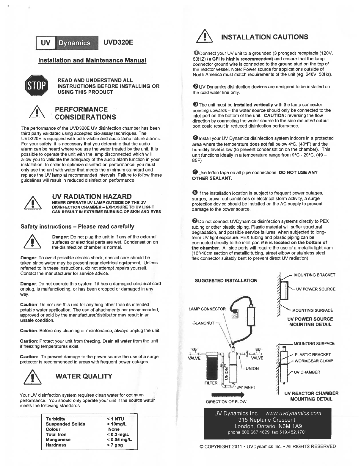
SUGGESTED
INSTALLATION
LAMP
CONNECTOR
GLANONUT
MOUNTING
BRACKET
UV
POWER
SOURCE
MOUNTING SURFACE
LW
POWER
SOURCE
MOUNTING
DETAIL
Caution:
Before
any
cleaning
or
maintenance, always
unplug
the
unit.
Caution:
Protect
your
unit
from
freezing.
Drain
all
water
from
the unit
if
freezing
temperatures
exist.
Caution:
To
prevent damage
to
the
power
source
the
use
of
a
surge
protector
is
recommended
in
areas
with
frequent
power
outages.
WATER
QUALITY
Your
UV
disinfection
system requires
clean
water
for
optimum
performance.
You
should only operate
your
unit
if
the
source
water
meets
the
following
standards.
ISi~~_ab
~‘
b1
VALVE
‘~
VALVE
IJN1ON
I
0•
FILTER
1
~3I4’MNPT
UV
REACTOR
CHAMBER
MOUNTING DETAIL
MOUNTING
SURFACE
PLASTIC
BRACKET
WORMGEAR CLAMP
UV
CHAMBER
I
DIRECTION
OF
FLOW
Turbidity
<1
NTU
Suspended
Solids
<lOmgIL
Colour
None
Total
Iron
<0.3
mgIL
Manganese
<0.06
mg/L
Hardness
<7
gpg
UV
Dynamics
Inc. www.
uvdynarnics.
corn
315
Neptune Crescent.
London. Ontario,
N6M
1A9
phone
800.667.4629
fax
519.452.1701
©
COPYRIGHT
2011
UVDynamics
Inc.
•
All
RIGHTS
RESERVED