WDT GRANUDOS 10-V61 User manual

WDT Operating instructions GRANUDOS 10 (V61-08/05) page 1 of 20
____________________________________________________________________________
Series No.....................................Customer.....................................Date of delivery...................
Operating instructions GRANUDOS 10-V61
Safety Devices
1. Chlorine and acid may not be mixed together or
with other chemicals
Pay attention to the safety devices on chemical
Containers
2. Close hopper immediately after filling
3. If an adapter to a chemical container is used the
hopper must be screwed even and firmly to the
container
4. Clean environment with water if chemical was
spread
5. Only instructed personnel may work with the
GRANUDOS
6. Ensure booster pump does not run dry, always
isolate pump when backwashing.

WDT Operating instructions GRANUDOS 10 (V61-08/05) page 2 of 20
____________________________________________________________________________
TABLE OF CONTENTS
page
1 Function of GRANUDOS 10V61 3
1.1 Data, Measures, Performance 3
1.2 Dosing Assembly Chlorine 4
1.3 Dissolving System 5
1.4 Acid dosing 6
1.5 Control Panel (GRD V61) 6
1.5.1 Programme selection 6
1.5.2 Monitoring of external auto-controller 7
2 Installation 8
2.1 Tubing 8
2.2 Electrical Connection 9
3 Start up operation 9
3.1 Deaeration of water supply tubing 9
3.2 Water level in flushing tank 9
3.3 Water flow/Suction performance of injector 9
3.4 Filling of Chlorine into hopper 9
3.5 Adjusting the pump pressure switch
3.6 Providing of acid 9
3.7 Dosing Performance Adjustment 10
Diagram and table to determine dosing performance 11
3.8 Dosing controlled by Auto-Controller 11
4 Diagnosis programme 13
4.1 Starting self check 13
4.2 LED Indicators 13
4.3 Irritations not monitored/indicated by switches 15
5 Maintenance – taking out of operation 16
6 Control plate/relay /Fuses 17
7 Spare parts list 19
8. Maintenance List 20

WDT Operating instructions GRANUDOS 10 (V61-08/05) page 3 of 20
____________________________________________________________________________
1 Function of GRANUDOS 10V61
1.1 Data, Measures, Performance
The GRANUDOS 10-V61 dosing system comprises:
-polyethylene housing one piece
-filling hopper 5 kg (option 10 kg or adapter to 10 kg containers)
-calcium hypochlorite screw feed arrangement
-peristaltic acid pump
-dissolving system
Measures:
base: 60 x 50 cm
height: 80 cm
weight: 30 kg
Material:
PE, polyethylene
Booster Pump
centrifugal pump: SS - 0.3 kW, 230 Volt
supply pressure: 0,2 – 1,2 bar
counter pressure: 0 – 1,2 bar
(depending on supply pressure)
water flow: app. 1000 l/h
Dosing performance:
chlorine: 1 kg/h
acid: 1,5 l/h
Fault remote indication
by relay
1 supply carboy lance
2 dosing pump for acid
3 strainer GR 10 complete
4 control system
5 dosing hopper
6 dosing assembly GR 10
8 floating valve d25 complete
9 booster pump
10 suction tube with flow switch
11 acid dosing valve GR
12 mixing cyclone GR 10
13 venturi complete
14 level switch GR 10

WDT Operating instructions GRANUDOS 10 (V61-08/05) page 4 of 20
____________________________________________________________________________
1.2 Dosing Assembly
The dosing assembly, placed into the main housing consists of the dosing hopper (5a) and the dosing
unit with dosing motor (6a) pushed into and screwed to the motor holder (6b) the dosing
screw (6c) and the dosing nozzle which is heated eliminating condensation of the warm pool water
vapour. The dosing unit is screwed into the dosing hopper. The required dosing rate is adjusted at the
control board by means of a dosing cycle and dosing time – see para 1.5.
5a dosing hopper
5b hopper cover
6a dosing motor
6b motor holder
6c dosing screw
6d heated dosing nozzle
6e knocker
The knocker (6e) gives a stroke to the dosing hopper wall
and thus prevents clogging of the chemical.
The complete dosing assembly can be taken out of the
frame for service.
With the shown fitting systems chemical containers of 10 kg can be fitted directly to the hopper so that
the chemical must not be moved from the container to the hopper.
Fitting system to join a Fitting system to join a
10 kg container with round edge 10 kg HTH container

WDT Operating instructions GRANUDOS 10 (V61-08/05) page 5 of 20
____________________________________________________________________________
1.3 Dissolving System
The dissolving water is normally supplied from before or from behind the filter. There must be a
sufficient supply pressure to avoid dry running and/or cavitation on the booster pump, at least
0.2 bar. The pump pressure is controlled by the pressure switch (20) fitted on top of the pump. At a
pressure below the set switch pressure by sucking air or at pressure drops the machine stopps, lamp 1 &
2 will burn. At works 1,5 bar is set.
The supply water is divided at the discharge of the booster pump (26), one way leading to the flushing
tank (22), the other branch directed to the venturi nozzle (25), where the water is sucked together with
the dosed chemicals out of the flushing tank. The supply water flow is controlled by means of a floating
valve (21) and a flow switch (24), the latter being installed in the suction tube of the venturi. To mix the
chemicals and to ensure the complete dissolving of the chlorine granules a cyclone mixing chamber
(27) is fitted after the venturi.. To ensure that
chlorine
and acid do not come into contact with each
other in the open tank part of the dissolving assembly a sophisticated control system is installed:
-metering of the two chemicals is regulated with pauses between the metering intervals (para 3.7
“Adjusting dosing performance”).
-power supply for chlorine and acid dosing motors are connected by a relay system so that only one
or none of them can get power (24VDC) and dose chemical.
-flow switch (24) , level switch (29), pressure switch (20) supervising water supply and flow
conditions. If any non-compliance with the given limits occurs, the GRANUDOS will be switched
off.
If any non-compliance with the given limits occurs, the chemical dosing will be stopped.
7 pressure switch 13 venturi nozzle
8 floating valve 14 orifice washer
9 booster pump Lo 2HM 3 15 level switch low/high
10 flow switch holder with flow switch 16 lid on flushing tank
11 acid dosing valve with chlorine dust protection
12 mixing and dissolving 17 overflow to drain
chamber with PVC ball valve
The flushing tank is an open system with two ways for a drain of water coming from the circulation to
the flushing tank and possibly causing an overflow at switch off times. To avoid this, the flow switch
holder as the floating valve are acting as non return valves: The floating valve closes the inlet bore at
rising level (proved up to 4 bars at test), in addition a spring loaded non return valve is installed in the
elbow fitting into the valve. The switch bobbin has a seal to close this way. Both devices function well
if the seal/diaphragm are maintained in a good shape. But as a mechanical seal may leak after any time
or by being blocked by impurities a 100% isolation may not be guaranteed. If this is needed for any
cases, an electric valve must be installed.
7
8
9
10
11
12
14
13 15
16 17

WDT Operating instructions GRANUDOS 10 (V61-08/05) page 6 of 20
____________________________________________________________________________
1.4 Acid Dosing
The acid required either for pH-control or just for cleaning of the
flushing, mixing and dosing system is metered by the peristaltic pump
to the flushing water via the dosing injector (11). As the cleaning
procedure is vital for the correct function of the complete dosing
assembly, chlorine dosing is stopped if the level switch at the supply
carboy lance indicates container empty.
Please do not use concentrated hydrochloric acid for this duty as that
penetrates the peristaltic hose and will destroy the pump head.
1.5 Control Panel
The microprocessor based control of the GRANUDOS has three functions:
- Contains the circuit self check and dosing programmes for chlorine and acid
- Function control and interruption display (1 green + 4 red LED). If any
interruption is displayed, the GRANUDOS is switched off - 'Chemicals on
reserve' is only indicated. All faults normally activate the fault remote
control.
The control system is enclosed within a dust
proof and splash proof housing (IP 65). External
switches and fault remote indication are to be
connected in the lower part of the housing.
1.5.1 Programme Selection (GRD 61)
P: Proofing programme for control board, only
used by authorised personnel
For test and check of dosing motors:
C5: Continuous dosing of chlorine for 5 minutes
A5: Continuous dosing of acid for 5 minutes
After the 5 minutes dosing the green LED will flash
continuously
ECA: External control of chlorine and acid by an
auto controller
EC: Auto control only chlorine, acid dosing
continuously as set, but only if chlorine is
dosed
E15: Monitoring of the external auto controller
chlorine and acid: After an excess time of 15
minutes dosing stops.(see next para)
E60: Monitoring of the external auto controller
chlorine and acid: After an excess time of 60
minutes dosing stops.(see next para)
When changing a programme there is always a delay of 4 seconds until the new programme
is verified. During this time the green lamp will flash.

WDT Operating instructions GRANUDOS 10 (V61-08/05) page 7 of 20
____________________________________________________________________________
1.5.2 Monitoring of external controller and dosing with programme E15/E60
When controlling the GRANUDOS dosing by an external controller the dosing performance must be set
high enough to ensure the dosing time of acid and chlorine dosing motors shall not exceed 50% of total
time, the actual values are normally near to the set points of free chlorine and pH. If control time
exceeds 50% , there must be an interruption in the system:
-too high bathing load
-interruption at the dosing appliance: blocked screw, broken hose, faulty motor etc.
-interruption at the auto control system: hanging relay, faulty electrode etc.
The GRANUDOS controller adds up all ordered dosing time (input time) that exceeds
50% of total time and stops dosing if a certain excess time is reached: 15 minutes with
programme E15, 60 minutes with programme E60. Indication by flashing of all 4 red lamps.
Dosing can be switched off by an additional external switch e.g. a flow por pressure switch
in the measuring water tubing or in the circulation to prevent dosing if there is an
irritation

WDT Operating instructions GRANUDOS 10 (V61-08/05) page 8 of 20
____________________________________________________________________________
2. Installation
2.1 Tubing – please see installation diagram page
For satisfactory water flow through the dissolving system the supply pressure must be at least 0,2 bars.
At low service pressure the counter pressure must be low, too. Counter pressure and pressure loss in
the dosing line should be as low as possible. At works the GRANUDOS has been tested at following
pressure conditions:
Service pressure 1,2 bars Counter pressure 1,2 bars
0,6 bars 0,8 bars
0,3 bars 0,5 bars
Within these ranges the GRANUDOS should function well. In addition please pay attention to the
following:
1. Tapping point for supply water to be between filter and heat exchanger, dosing point after heat
exchanger.
2. Ensure that the tapping/dosing points are free flowing and not blocked by scale or corrosion.
3. Pipe runs to be kept as short as possible. PVC-tubing 25 mm or hose 1´´. For longer distances
or poor pressure conditions use bigger tubing.
4. Use high quality PVC ball valves.

WDT Operating instructions GRANUDOS 10 (V61-08/05) page 9 of 20
____________________________________________________________________________
2.2 Electrical connection
The electrical supply of the GRANUDOS has to be controlled by the electrical supply of the
circulation pumps that dosing can only be with water circulation and accordingly water supply to
GRANUDOS. The GRANUDOS has to be stopped and isolated at back washing, too! See wiring
diagram
To connect external systems to the GRANUDOS please use only flexible cable type.
Electrical works are only to be executed by authorised people.
3Start
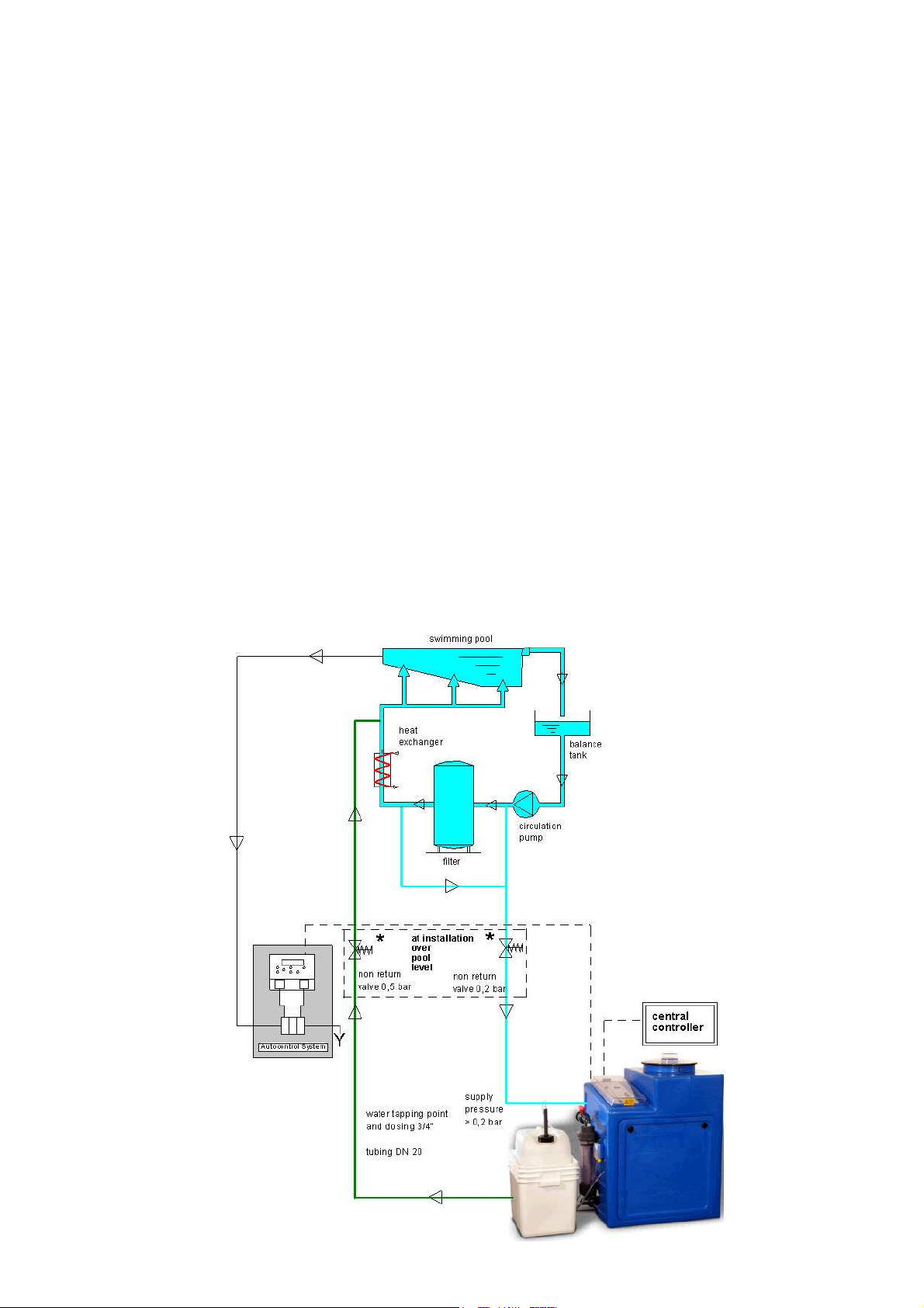
After having executed points 2.1 and 2.2 open the ball valves at the tapping points and at
GRANUDOS. Press floater of floating valve inside the tank down to let water flow into the flushing
tank. When the flushing tank is half full switch on the GRANUDOS mains as the booster pump of
GRANUDOS should not run dry.
To ensure correct dosing of the chemicals water flow through the flushing tank must run in the correct
way as described below.
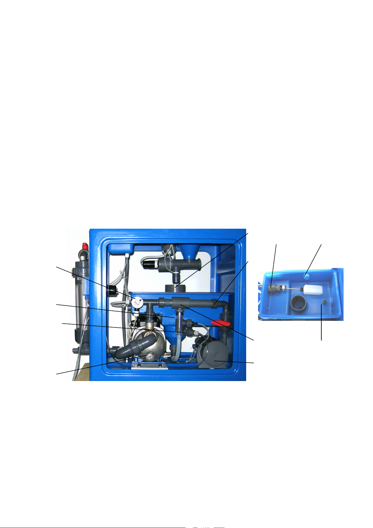
3.1 Check of pump
Check by means of a screw driver at back shaft of the pump whether the shaft is turning easily. If not
the slide ring seal is blocked. Try to loosen it by rapid moving of the shaft right and left. If no success,
the pump must be dismantled completely and the slide ring loosened. If this is not done, the pump will
leak in short time as the O-ring on the shaft will be worn.
3.2 Deaeration of the water supply tubing
At switching on the GRANUDOS take care to deaerate the supply water tubing completely. For this
please observe the water level inside the pre-filter. If he get’s empty switch off the pump/machine and
wait till the filter is full again, then switch on again. On operation the filter must be and stay full of
water; a little air at top staying steadily does not matter. The deaeration procedure can take some
minutes depending on the length of the supply tubing.
Attention! If electric valves are installed to isolate the machine the supply valve must be opened
manually as otherwise the pump can not be deaerated and the pressure switch would not allow
the pump to run.
3.3 Water level in the flushing tank
Water level in the tank should be maintained at half full. To obtain a higher level unscrew float rod,
for a lower level screw in the float rod. One turn gives about 1 cm in height.
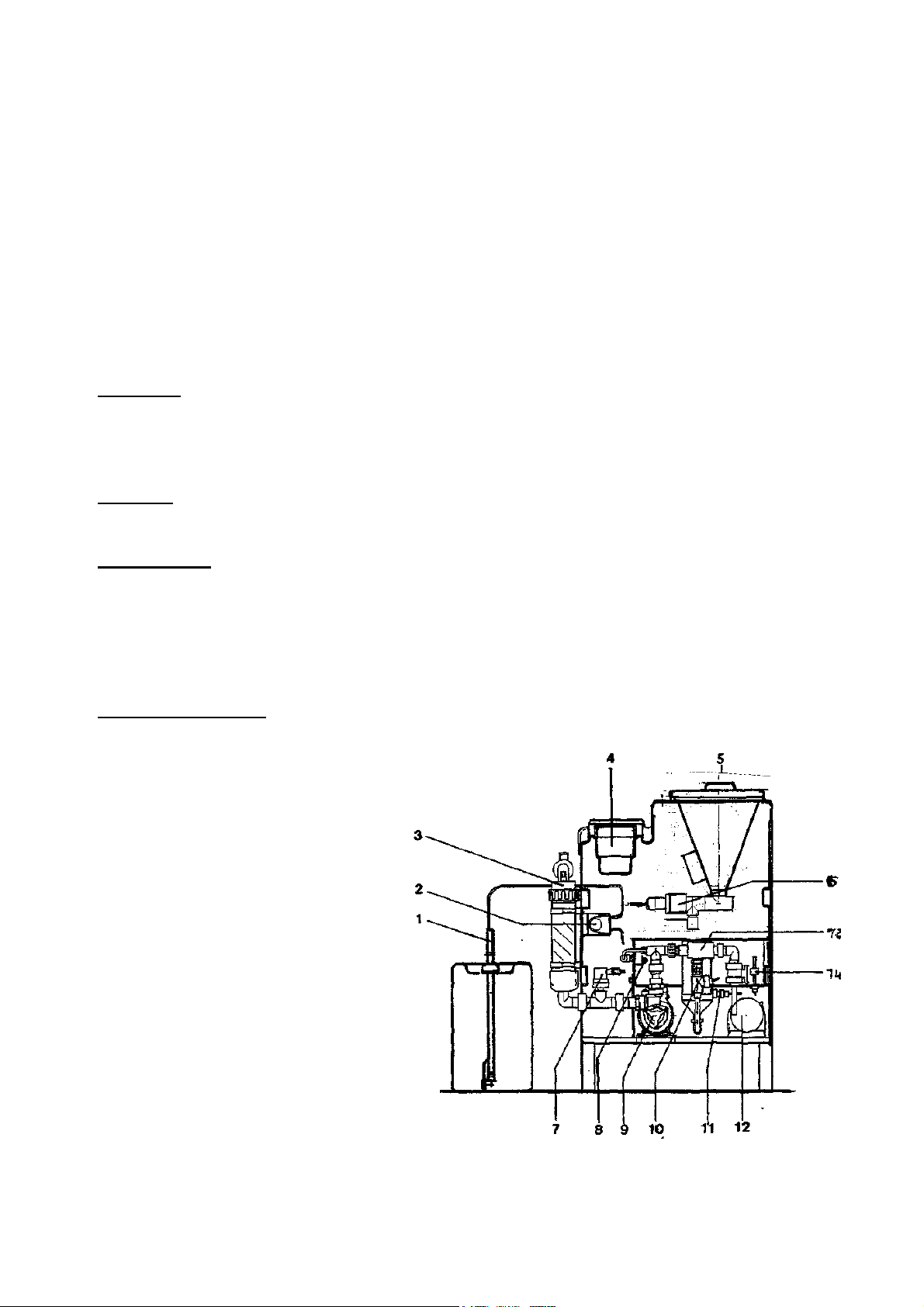
3.4 Water flow/Suction performance of the venturi
At stable water level the switch bobbin of the flow switch inside the suction tube (10) should definitely have
risen up to the top, the control lamp of the switch may not burn.
To adjust the water flow to the pressure conditions of the filter system a nozzle is inserted in the union (13c)
behind the venturi. If water level in the tank tends to run low or if switch bobbin is at top without pump running
(too high suction at the venturi – high pressure difference between tapping points ) fit the nozzle with the 5,5
mm diameter hole you find in the spare parts kit. If the water level tends to run high and/or suction is too low –
switch bobbin does not rise (too high counter pressure?) put in the 7 mm nozzle or use without nozzle.
3.5 Adjusting the pressure switch
The pressure switch is fitted pressure side of the booster pump, so monitoring the real pressure. If air is
sucked by the pump or at pressure drops the pump is switched off to avoid:
-overdosing if circulation is disturbed
-the booster pump is not destroyed by cavitation or running dry

WDT Operating instructions GRANUDOS 10 (V61-08/05) page 10 of 20
____________________________________________________________________________
The pressure switch is working from 1-3 bar. To adjust the switch to the working conditions take off the switch
cover, turn clockwise the switch knob till the pump switches off, then turn back a little. As the GRANUDOS is
now on fault, the machine must be restarted by switching the machine to “off” till the 2 red lamps are off, then
“on” again at the front plate. Now the GRANUDOS runs again and will be stopped if the pump pressure falls
down to the set pressure.
If additional pumps are switched on or off in filtering service (e.g. pump from balance tank) the switch must be
adjusted without the additional pump. At works the switch is adjusted to 2 bar.
3.5 Filling of chlorine into the hopper
Before carrying out any task involving chemicals the operator should put an personal protective
equipment to provide adequate protection to eyes, respiratory orifices, hands and clothing.
-Lid of control box is closed. Open the chlorine hopper lid.
-Fill the chlorine into the hopper carefully to the hopper wall with help of a scoop from the
drum that no chemical dust will arise.
-Fill in only the consumption of chlorine for appr. 2 weeks.
-After filling the hopper carefully cover the lid of the chemical drum again.
-Close the hopper lid.
3.6 Acid dosing
The acid dosing pump mounted left side of the housing is delivered with loose dosing hose to prevent
deformation on stock time. Push the hose back into the yellow housing and turn the roller clockwise
some times so that the hose is situated even back in the housing. Then push the safety disc on the shaft
and the pump cover –both in the small bag attached above the pump. Position the acid container beside
the GRANUDOS, open it and put the acid lance into it. Push the “Test” button for acid. If no fault
indicates, acid must now be sucked up through the transparent suction tube to the pump and further to
the dissolving system.
As acid use one on base of sulphuric acid (37 – 50 %). Do not use concentrated hydrochloric acid as
this damages the peristaltic pump.
3.7 Adjusting the dosing performance of GRANUDOS
On principle dosing of the GRANUDOS is working to the following scheme where the dosing cycle is
set on 32 seconds – cycle knob on 16:
On the dosing cycle and dosing time knobs the scale of 1-16 is set to give the most
appropriate cycle time and dosage to suit the individual pool. The diagram and table below
shows the cycle timing and given values for various settings
Dosing Performance Adjustment
1. Chlorine
In principle the chlorine consumption of a pool depends on a variety of influences:
Loading, temperature, required chlorine concentration etc. Normally a standard indoor pool
needs about 300 g of calcium hypochlorite per 100 m
3
in volume per day. So a pool of 600 m
3
in volume needs app. 1800 g/day or app. 75 g/h at continuous dosing. These 75 g/h
corresponds to app. 3 % of the maximum dosing performance of 2 kg/h. This is achieved with

WDT Operating instructions GRANUDOS 10 (V61-08/05) page 11 of 20
____________________________________________________________________________
a cycle time of 138 seconds –Position 8 at the cycle knob and a corresponding dosing rate of
13 % - position 4 at the dosing time knob.
An outdoor pool needs in good weather conditions about 3-5 times more chemical.
2. Acid
The consumption of acid is harder to predict as that of chlorine. For the beginning set the
dosing knob similar to chlorine. The actual need has to be found by trial and error. The pH
should be at 7,0 – 7,4.
3.5 Dosing Controlled by Auto-Controller
If an auto-controller is used, set an “E-Programme” – see above and use app. 3-5 times higher
dosing rate as calculated above. It is to adjust both, cycle and dosing time.
If CO2 is used for pH-correction, it is proposed to connect the controller output at the
GRANUDOS in parallel to the CO2 control valve and set a low dosing performance for acid.
So the acid dosing for cleaning is controlled.
Attention!! If an external auto-controller has a solid state relay (transistor) output there can be
an leakage voltage even the controller switches off the dosng. To avoid that the GRANUDOS
input relay is switched by this leakage voltage a resistor 15 kohm, 4,5 w must be fitted in
parallel.
To connect the auto-controller to the GRANUDOS please see the wiring diagram

WDT Operating instructions GRANUDOS 10 (V61-08/05) page 12 of 20
____________________________________________________________________________
Diagram for the Determination of the Switch Positions for the Cycle and Dosing Time
Table for Cycle amd Dosing Times
Switch
Cycle Time
Dosing Time
Position
Chlorine Acid
Sec. %
Sec. %
Sec. %
1
439 6
0,5 3
0,5 6
2
411 8
1 6
1 13
3
342 9
1,5 9
1,5 19
4
285 11
2 13
2 25
5
238 13
2,5 16
2,5 31
6
198 16
3 19
3 38
7
165 19
3,5 22
3,5 44
8
138 23
4 25
4 50
9
115 28
5 31
4,5 56
10
95 34
6 38
5 63
11
80 40
7,5 47
5,5 69
12
66 48
9 56
6 75
13
55 58
10,5 66
6,5 81
14
46 69
12 75
7 88
15
38 84
14 88
7,5 94
16
32 100
16 100 8 100
The percentage values of the performance table are to be related to the maximum dosing rates:
GRANUDOS 10: Chlorine app. 1. kg/h. acid app. 2 1/
Cycle Time Dosing Performance Dosing Time
Acid Chlorine

WDT Operating instructions GRANUDOS 10 (V61-08/05) page 13 of 20
____________________________________________________________________________
4 Diagnosis Programme / LED Signification (GRD 61)
4.1 Starting self check programme
When the machine is switched on a diagnosis programme for the control equipment runs. The same
happens when the reset key is pressed.
1. All lights burn together 3 seconds
1. Each light comes on one after another for one second
2. If there is no fault, all red lamps go out and the dosing programme commences.
4.2 LED Indicators for function and irritations
Green LED – indicates program switch and external inputs
on contiuously: GRANUDOS in operation
no light:Transformer Tr. 2 or fuse F1 for control system burnt
fast blink (0,5 second on, 0,5 second off...)
- Programme knob not on a programme station
- End of test programme A 5, C 5
-
Dosing switched off with front fascia switch
Glimmering: indicates filling of buffer tank with programme PB
Red LED
shows function of dosing and interruptions indicated by the different
Sensors. At any interruption dosing stops.
Glimmering:indicates dosing: L3 = acid, L4 = chlorine
on continuously: Interruption indicated by a sensor (see below)
slow blinking: (2 seconds on, 2 seconds off....) fuse of an output is burnt
LED (red) signal Interruption indicated – more detailed below
L1 on continuously Venturi suction - water flow too low, water level high
(more details see below)
L1 + fast blink Fuse F3 burnt (power 24 VDC–800 m amp slow) or
L4 slow blink together transformer Tr1 faulty
L2 on continuously
water level in tank low. water supply pressure low
(more details see below)
L3 on continuously acid container empty
L4 on continuously Chlorine drum empty
L4 slow blink fuse F4 burnt (chlorine dosing motor – 315 m amp slow)
L1 to L4 all blink together monitoring of dosing time active: ordered dosing time of controller
exceeds 50 % of total times for 15/60 minutes with programmes
E15/E60 ( dosing performance too low)

WDT Operating instructions GRANUDOS 10 (V61-08/05) page 14 of 20
____________________________________________________________________________
L1 on continuously: Water level in flushing tank too high, suction too low
There is coming more water to the tank as is sucked through by the venturi.
1. Suction power of venturi is O.K.: switch bobbin of flow switch in suction tube is at top of tube.
By pressing the supply hose to the suction tube the bobbin goes down and switch LED burns.
If loosened again, bobbin goes up quickly and switch LED goes out.
In this case there should be a fault in the floating valve: check whether by moving the floater
slowly up and down the incoming water flow decreases or increases steadily. If so adjust water
level by turning the floater rod one turn right. If floating valve does not work steadily, fit a new
valve membrane.
2. Suction power of venturi is not enough: switch bobbin of flow switch in suction tube is at
bottom of tube. By pressing the connecting hose to the suction tube the bobbin does not move,
switch LED burns.
Possibilities:
-at installation: service pressure too low – counter pressure too high. tubing faulty or too
small: take out orifice washer (13c) from union behind venturi.
- Booster pump performance too low – see pressure limits at para “Installation – piping”.
Fit the supplied pressure gauge to inlet and outlet to check pressure situation.
- Particles inside venturi or at outlet nozzle of flushing tank (good possibility at installation)
- Suction tube and/or mixing cyclone are turbid by calcium: acid dosing too low:
if there is still a little suction this can be easily cleaned by pouring hydrochloric acid or
special cleaning chemical into suction cone of the tank.
After cleaning increase acid dosing performance.
L2 on continuously: Water level in tank too low
Suction power of venturi is higher than water is supplied.
Possibilities:
- suction power too high: fit an orifice washer (13c) of 5,5 mm inside union behind venturi.
- supply water tubing is blocked
- too low supply pressure
- floating valve cone into flushing tank is blocked by particles, diaphragm is faulty

WDT Operating instructions GRANUDOS 10 (V61-08/05) page 15 of 20
____________________________________________________________________________
4.3 Irritations not indicated by monitoring switches
1. No chlorine dosing: no free chlorine in pool water
By using the test program chlorine on facsia no dosing
-dosing screw blocked
-dosing screw loose
-dosing nozzle (heated) faulty or blocked
-dosing motor faulty
If dosing works by using the test program see to auto-controller for free chlorine whether the
output is correct
2. No acid dosing: pH in pool water is high, suction tube/mixing chamber is turbid.
If acid container is not empty, no fault indication at the fascia: check dosing function of acid pump
use test program for acid. If pump runs, see whether an air bubble is sucked to pump, if not
examine the pump roller and pump hose. If all is OK, increase dosing rate and choose lower set
point for pH
3. Continuous dosing of chlorine or acid on program “auto” without command from the
auto-controller: Check whether the output from the auto-controller is correct – no voltage from
there. If so, the 130 volt relay of the GRANUDOS input is faulty. Replace the relay or mount a
new power plate.
4. Overflow from tank too much at switch off of GRANUDOS
-switch bobbin of flow switch is blocked on top situation or does not fall down completely
-joint of switch bobbin faulty
-diaphragm of the floating valve faulty
-piston of floating valve is blocked by impurities (sand if diaphragm is faulty)
-supply pressure of an external booster pump too high
-set in spring-loaded check valve in ell of floating valve. Please make sure that because of
pressure drop you will need a pressure of at least 0,4 bar

WDT Operating instructions GRANUDOS 10 (V61-08/05) page 16 of 20
____________________________________________________________________________
5. Maintenance
It is strongly recommended that a regular maintenance programme is undertaken. Consult your
installer/supplier and take up a service/maintenance agreement. This way the machine will be
maintained in good operating condition.
Minimum checks include the following items:
- maintain the environment of the machine clean
-clean strainer if necessary – a scaled filter causes cavitation and consequently damage of the
booster pump
For cleaning take out the complete filter from the machine and clean the insert
outside
-maintain the machine clean – especially the booster pump
-pay attention to any noise of the pump: cavitation, bearings – if so, contact your supplier
-check monthly for the acid pump whether the springs are o.k. If corrosion can be seen, change
the dosing hose. In any case change it once per year.
-monthly or with each new drum check function of all sensors i.e. water flow, level and empty
switches
-every 2 months clean the chlorine dosing screw: dismantle the hopper and take out dosing
motor with the screw, clean with a brush – do not use water
-change membrane of floating valve once per year
-change seal of flow switch bobbin all ½ year
-check once per year acid dosing valve – change seals
Taking out of service
-disconnect acid dosing hose (or use a new one at starting again)
-empty the dosing hopper, take out chlorine dosing screw, clean it thoroughly and store it at a
dry place
-clean all parts of GRANUDOS thoroughly.
-leave the GRANUDOS switched on - programme switch on “0"
-clean the environment of the machine thoruoghly.
At taking into operation again
please pay attention to the para 3. Start up procedure

WDT Operating instructions GRANUDOS 10 (V61-08/05) page 17 of 20
____________________________________________________________________________
7. Wiring Diagram/Fuses
6.2 Fuses, transformers, relays
Fuses FO mains fuse in front plate 3,15 amp slow
F1 fuse control plate 315 m amp slow
F2 Fuse booster pump 3,15 amp slow
F3 fuse power output except chlorine dos. motor 800 m amp slow
F4 Fuse chlorine dosing motor 315 m amp slow
Transformers
Tr1 transformer for power outputs 18 volt, 16 va
Tr2 transformer for control system 6 volt, 1,5 va
Relays
SSR. 1 solenoid knocker 240 v (solid state relay)
Rel. 2 booster pump 240 v
Rel. 3 relay auto control chlorine
Rel. 4 relay auto control acid
Rel. 5 fault remote control non volt
Rel. 6 internal locking chlorine dosing
Rel. 7 internal locking acid dosing
2 3 4 561
STR1
Tr1
Tr2
Rel.2
Rel.3
Rel.4
Rel.5
Rel.6
Rel.7
ribbon cable
Code in
plug
2 3 4 561
1 2 3 4
123 4 5 6 7 8
123 4 5 6 7 8
123 4 5 6 7 8
123 4 5 6 7 8
S 010
S 011
S 012
S 01
S 02
S 03
S 04
Code at
Power-card

WDT Operating instructions GRANUDOS 10 (V61-08/05) page 18 of 20
____________________________________________________________________________
clamps for 230 VAC 6 x 5 mm
plug S010 (coding on clamp 1) plug S011 (coding on clamp 6)
1 - 195 VDC knocker 1 N pump
2 + 195 VDC knocker 2 L pump
3 SL 3 SL
4 N supply 4 N solenoid valve
5 L supply 5 L solenoid valve
6 SL 6 SL
plug S012
external control 230 VAC
Attention !!! external voltage from the controller !!!
1 – 2 chlorine ext. 230 Volt
3 – 4 pH ext. 230 Volt
clamps 8 x 3,5 mm low voltage / volt-free
plug S01 (coding on clamp 8) plug S03 (coding on clamp 3)
controlled outputs 24 VDC switch of dissolving unit
(normal open)
1 – 2 heater dosing nozzle 1 level W max (blue)
3 chlorine dos. –24 VDC 2 level W min (brown)
4 chlorine dos. +24 VDC 3 mass level switches (black)
5 acid dos. –24 VDC 4 pressure min
6 acid dos. +24 VDC 5 + 24 VDC
6 mass
7 – 8 fault remote control volt-free 7 low flow / suction
8 mass
plug S02 (coding on clamp 6) plug S04 (coding on clamp 1)
for external control. empty switch chlorine / acid
switch functions are activated by
the closing of the switch contact
1 chlorine control volt-free 1 mass
2 pH-control volt-free 2 acid empty
3 (-) mass for control switch 3 mass
4 shock dosing (back flow dis.) 4 chlorine empty cap (option)
5 ext. switch-off of the dosing 5 + 24 VDC for chlorine empty
6 ext. Switch for GR off (=W min) 6 mass
7 +24 VDC 7 free
8 - 24 VDC – mass 8 mass

WDT Operating instructions GRANUDOS 10 (V61-08/05) page 19 of 20
____________________________________________________________________________
8. Spare Parts GRANUDOS 10-V61
Designation Item No.
Chlorine dosing dosing hopper 5 kg 12798
Cover for dosing hopper GR 10 12353
dosing motor PLG 30-35 11676
Motor holder PLG- d25 11541
dosing screw d6/D19 (GB) 11549
dosing nozzle heated GR 11556
knocker GR 10 complete 12868
Acid dosing Acid pump Sa complete 11628
Pump housing Sa 12702
Roller Sa 12609
Dosing hose 3.2x1,6 Sa 12782
Supply carbuoy lance 12523
acid injection valve GR 11633
Repair set for acid valve 11636
Filter Filter housing 12746
Filter top with ball valve d25 12304
O-ring on top 11258
Control system Control plate MCU 1c 11505
Power plate NRGRD-6 11517
Power transformer, 240/18 volt, 16VA 11665
Control transformer 240/6V-2VA 10929
main switch 11338
fuse holder GR 12324
Knob 4mm 11757
Cover control box GR10 10796
Floating valve floating valve d25 GR10 complete 17006
diaphragm for floating valve 16367
non return valve d8 0,4 bar spring loaded GR10 16652
floater 11621
Level switch level switch GR 10 10497
Booster pump booster pump Lo 2HMS3-A 10657
maintenance set: ball bearings, slide ring seal 17019
Flow switch suction tube GR ½´´ – S14-US 12729
flow switch GR ind. 18x1 long lead 12430
flow switch bobbin GR ind. ½´´ 12730
seal ring Vi 14/8,7 flow switch bobbin 15801
connecting hose Si 10/2,5/170 11565
Venturi venturi GR10 complete 11792
orifice washers for venturi-kit 11594
venturi-nozzle ½´´ 12306
venturi-body with connector ½´´ 12305
Cyclone mixing cyclone GR 10 12329
Maintenance kit For yearly maintenance: seals, diaphragms, fuses all GR
12631

WDT Operating instructions GRANUDOS 10 (V61-08/05) page 20 of 20
____________________________________________________________________________
6 . Maintenance List GRANUDOS 10/45/100
Object:..........................................................................................................…….........………... .….………..
GRANUDOS-Type:..................................................... series no...................….....…………....
Maintenance executed by …………………………….. date:.......................……….…..…….....
Sign of pool operator:...........…………...............................................................…………………………….....
This has to be done
↓
↓↓
↓
This was necessary too
↓
↓↓
↓
↓
↓↓
↓
1 Dissolving system
↓
↓↓
↓
1.1 check level switch: OK [ ] change switch [ ]
1.2 check pressure switch: OK [ ] change switch [ ]
1.3 check flow switch: OK [ ] change switch [ ]
1.4 cleaning flow switch bobbin, fit new seal [ ] change bobbin [ ]
1.5 change diaphragm of floating valve [ ]
1.6 check function floating valve OK [ ] adjust water level [ ]
1.7 check connecting hose tank-flow switch holder [ ] change connecting hose if brittle [ ]
1.8 check pump end plate (at Calpeda pump only) [ ] change pump end plate [ ]
1.9 check tightness of pump OK [ ] new slide ring seal [ ]
1.10 check ball bearings: is it noisy? OK [ ] new bearings [ ]
1.11 clean pre-filter, if polluted [ ]
2 Dosing chlorine
2.1 check function heating nozzle: OK [ ] change nozzle [ ]
2.2 check function empty switch: OK [ ] change switch [ ]
2.3 check dosing screw, clean it dry OK [ ] change screw [ ]
2.4 check power dosing motor: OK [ ] change motor [ ]
2.5 change sealing of dosing motor [ ]
2.6 check clamp bands and safety belt [ ] change [ ]
3 Dosing acid
3.1 check function empty switch: OK [ ] change empty switch [ ]
3.2 check function dosing pump OK [ ]: change pump [ ]
3.3 change dosing hose [ ] change roller [ ]
3.4 change acid valve insert [ ]
4 Additional jobs
4.1 clean GRANUDOS carefully: [ ]
4.2 clean environment of the GRANUDOS [ ]
……………………………………………………………………………………………………………………………
……………………………………………………………………………………………………………………………
……………………………………………………………………………………………………………………………
……………………………………………………………………………………………………………………………
Table of contents
Other WDT Lighting Equipment manuals
Popular Lighting Equipment manuals by other brands

Algam Lighting
Algam Lighting MW-430Z manual

Genius
Genius GUARD GUIDE FOR THE INSTALLER

DS Produkte
DS Produkte LED6 instructions

Atlantis
Atlantis STUDIOLIVEMAX BXYOUTUB02 user manual

Feit Electric
Feit Electric BALL-1/LED Important Safety Instructions and Installation Guide

Teleco
Teleco TVLRGBDU868ST24 quick start guide