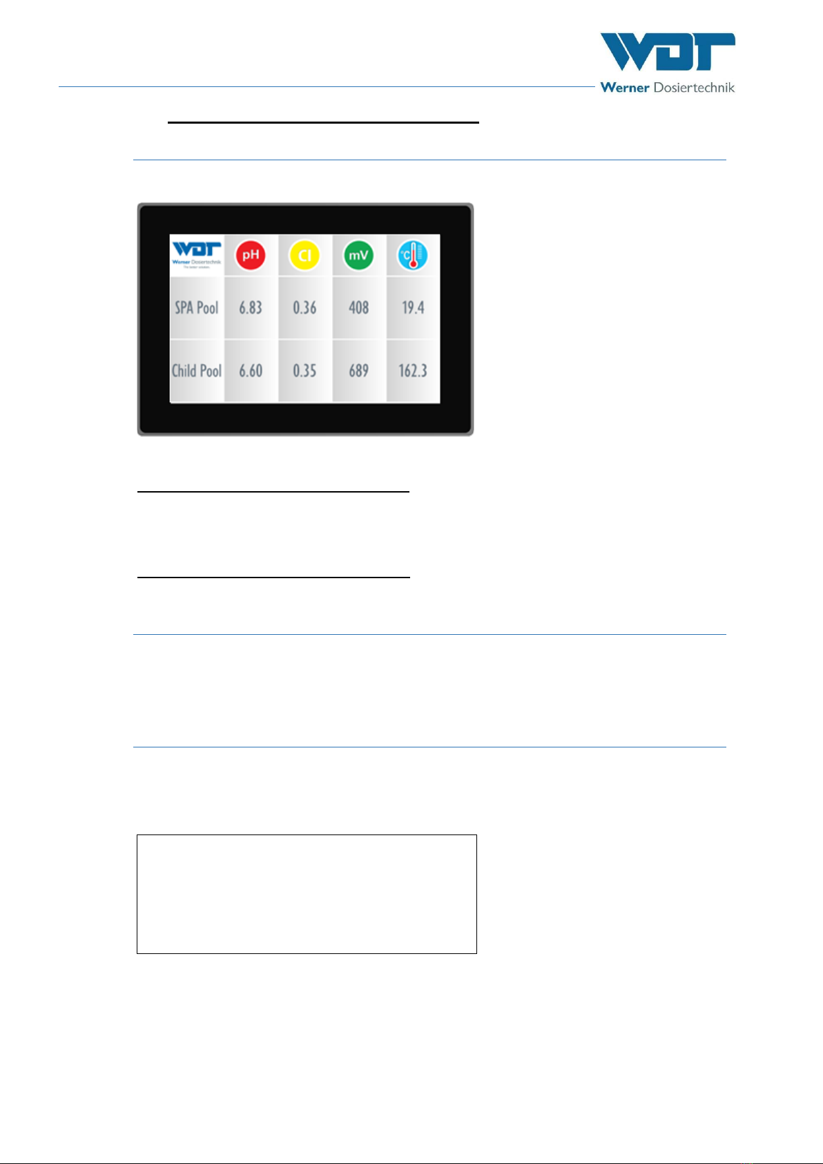
Tele Indication, Type 10” Touch-V1
Index: 00 Date modified: 01/08/2017 OI No.: BA MR 002-00 Fernanzeige V1 EN.docx Page 2 of 25
Table of contents
1About these instructions / general .......................................................................................................... 3
1.1 Scope of applicability ........................................................................................................................................3
1.2 Target group .................................................................................................................................................... 3
1.3 Symbols used ...................................................................................................................................................3
1.4 Warranty .........................................................................................................................................................4
1.5 Further information.......................................................................................................................................... 4
2Safety ...................................................................................................................................................... 5
2.1 Intended use.....................................................................................................................................................5
2.2 Safety notices ................................................................................................................................................... 5
3Product description –scope of delivery .................................................................................................. 6
3.1 Scope of delivery / accessories.........................................................................................................................6
3.2 Product description ..........................................................................................................................................6
3.3 Identification of the device / identification plate ...............................................................................................6
3.4 Technical data .................................................................................................................................................. 7
3.5 Transport / storage .........................................................................................................................................7
4Installation ............................................................................................................................................... 8
4.1 Select the installation site..................................................................................................................................8
4.2 Installation instructions (assembly suggestion) ..................................................................................................8
4.3 Mechanical installation ......................................................................................................................................9
4.4 Hydraulic installation ......................................................................................................................................10
4.5 Electrical installation .......................................................................................................................................10
5Commissioning ...................................................................................................................................... 10
5.1 Commissioning –comments...........................................................................................................................10
5.2 Commissioning work......................................................................................................................................10
6Operation / service............................................................................................................................... 11
6.1 General ..........................................................................................................................................................11
6.2 Control unit - Software ..................................................................................................................................11
6.3 The main menu ..............................................................................................................................................12
6.3.1 Login...................................................................................................................................................12
6.3.2 Main groups and symbols....................................................................................................................13
6.4 Main group Start Slideshow............................................................................................................................13
6.5 Main group Settings........................................................................................................................................14
6.5.1 Setting group Slide 1.1, Pool values Pool 1-4 ......................................................................................14
6.5.2 Setting group Slide 1.2, Pool values Pool 5-8 ......................................................................................15
6.5.3 Setting group Slide 3.1, Spa values Area 1-4 .......................................................................................15
6.5.4 Setting group Slide 3.2, Spa values Area 5-8 .......................................................................................16
6.5.5 Setting group Global settings...............................................................................................................16
6.5.6 Setting group System ..........................................................................................................................16
6.6 Main group Info..............................................................................................................................................19
6.7 Logout............................................................................................................................................................19
6.8 Configuration of the customer-specific information on the SD card ...............................................................19
7Maintenance, care, faults ....................................................................................................................... 22
7.1 Device maintenance .......................................................................................................................................22
7.2 Regular water check.......................................................................................................................................22
7.3 Fault removal / Error codes...........................................................................................................................22
8Decommissioning –Storage –Disposal................................................................................................. 22
8.1 General ..........................................................................................................................................................22
9Documents............................................................................................................................................ 22
9.1 Declaration of conformity ..............................................................................................................................22
9.2 Wiring diagrams.............................................................................................................................................22
9.3 Commissioning protocol ................................................................................................................................22
9.4 Operation data sheet......................................................................................................................................23
9.5 Maintenance protocol.....................................................................................................................................25
9.6 Spare parts list, wear parts list, list of consumables ........................................................................................25
10 Appendices............................................................................................................................................ 25