IDEC LB Series User manual
Switches & Pilot DevicesSignaling LightsRelays & SocketsTimersContactorsTerminal BlocksCircuit Breakers
ø16mm - LB Series Switches & Pilot Devices
496 www.IDEC.com
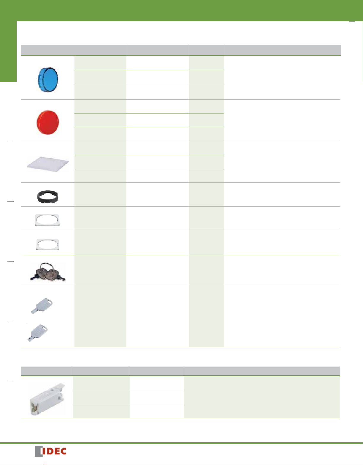
Replacement Parts
Item Material Part Number Remarks
Lens Forroundunits Polyarylate
ø15.4H4mm AL6M-Lk
Specifythecolorcodeinplaceofkinthepartnumber.
A:Amber,C:Clear,G:Green,R:Red,S:Blue,Y:Yellow
Note:Useaclearlensfororwhite(PW)illumination.
Forsquareunits Polyarylate
15.4,H4mm AL6Q-Lk
Forrectangularunits Polyarylate
W21.4xH4xD15.4mm AL6H-Lk
Button Forroundunits Polyarylate
15.4,H4mm AB6M-Bk
Specifythecolorcodeinplaceofkinthepartnumber.
B:Black,G:Green,R:Red,
S:BlueW:White,Y:Yellow
Forsquareunits Polyarylate
15.4,H4mm AB6Q-Bk
Forrectangularunits Polyarylate
W21.4xH4xD15.4 AB6H-Bk
MarkingPlate
Forroundunits Acrylic
ø13.7H0.8 AL6M-k
Specifythecolorcodeinplaceofkinthepartnumber.
B:Black,W:White
Seepage498fordimensionsandengravingarea.
Forsquareunits Acrylic
13.7,H0.8mm AL6Q-k
Forrectangularunits Acrylic
W19.7xH0.8(0.4)xD13.7mm AL6H-k
LockingRing
Forallunits Polyamide
ø17.9,H3.9mm LB9Z-LNP
Anti-rotationRing
Forstandardbezel
Metal
(Stainlesssteel)
17.9,t0.6mm
LB9Z-LP1
Anti-rotationRing
Forushbezel
Metal
(Stainlesssteel)
W21xH8.2xD20.6
t0.8mm
LB9Z-LP6
SpareStandardKey
Forkeyselectorswitches Nickel-platedBrass AS6-SK Seepage495fordimensions.
SpareWavekey
ReversibleWaveKey
Non-reversibleWaveKey
ForWavekeyselector
switches
Diecastzincalloy(nickelplated)
W14xH2xD30.8mm LA9Z-SK-n
SpecifyWavekeynumberinplaceofninthepartnumber.
0H:Standardwavekey(reversible)
1Hto2H:Reversiblewavekey
3Hto6H:Non-reversiblewavekey
Seepage495fordimensions.
LB Series Replacement LED Unit
Item Rated Operating Voltage Part Number kColor Code
LEDUnit DC5V LB9Z-LED5kA
G
PW
R
S
Specifycolorcodeinplaceofthekinthepartnumber.R:Red,G:
Green,A:Amber,S:Blue,PW:White
AllilluminatedLBseriescontainanLEDunit.
Useawhite(PW)LEDunitforyellow(Y)illumination.
AC/DC12V LB9Z-LED1k
AC/DC24V LB9Z-LED2k

Switches & Pilot Devices Signaling Lights Relays & Sockets Timers Contactors Terminal Blocks Circuit Breakers
497
800-262-IDEC (4332) •USA & Canada
ø16mm - LB Series
Switches & Pilot Devices
Safety Precautions
• TurnoffthepowertotheLBseriescontrolunitsbeforeinstallation,removal,
wiring,maintenance,andinspection.Failuretoturnpoweroffmaycause
electricalshocksorrehazard.
• Toavoidburningyourhand,usethelampholdertoolwhenreplacing
thelamps.
• Forwiring,usewiresofapropersizetomeetvoltageandcurrentrequire-
ments.Soldercorrectlyaccordingtotheinstructionsin“Wiring”and“Notes
onTerminalCover.”Impropersolderingmaycauseoverheatingandcreatea
rehazard.Also,whenusingtabterminals,usereceptaclesofappropriate
size.
Instructions
Wiring
1.Soldertheterminalsat350°Cwithin3secondsusinga60Wsolderingiron.
Sn-Ag-Cutypeisrecommended.Whensoldering,donottouchtheLBseries
withthesolderingiron.Alsoensurethatnotensileforceisappliedtothe
terminals.Donotbendtheterminalorapplyexcessiveforcetotheterminal.
2.Usenon-corrosiveliquidux.
Terminal Cover
Solder/tabterminal
InserttheterminalcoverintothecontactblockwiththeTOPmarkingsonthe
contactblockandtheterminalcoverinthesamedirection.
Note:Whenwiring,inserttheleadwiresintotheterminalcoverholesbeforesoldering.Afterwiring,
terminalcoverscannotbeinstalled.
StandardBezel
FlushBezel
Operating Environment
• DonotusetheLBserieswherecorrosivegasesexistorunderanenviron-
mentexceedingtheoperatingtemperatureandhumidityranges.Other-
wise,damagesduetocontactfailureorchangeofsurfacecolormayoccur.
• Majorpartsoftheswitchareplastic.Scratchesordamagesmayoccur
whenscrapedwithasharpobjectorappliedwithexcessiveloadorshock.
Notethatthismaycauseoperationandappearancefailureoftheoperator
andbezel.
• Adherenceofdetergent,cuttingoil,orspecialchemicalstotheswitch
mayresultinoperationfailuresandappearancefailuressuchaschangeof
surfacecolor.
Handling
Contacts(microswitch)
WhenusingNC(normallyclosed)andNO(normallyopen)contactsofthesame
microswitch,avoidconnectionsofdifferentvoltages,orconnectionsofdifferent
typesofpowersupplies.Failuretoobservethisinstructionmaycauseashort-
circuit.
Removing and Installing the Contact Block
1.Turnthelockingleveronthecontactblockinthedirectionoppositetothe
arrowonthehousing.Thenthecontactblockcanberemoved.
2.InsertthecontactblockwiththeTOPmarkingsonthecontactblockandthe
operatorplacedinthesamedirection.Thenlocktheunits,turningthelocking
leverinthedirectionofthearrow.
locking lever
Panel Mounting
Removethecontactblockfromtheoperator.Inserttheoperatorintothepanel
cut-outfromthefront,theninstallthecontactblocktotheoperator.
StandardBezel
TOP
TOP
Panel
➀
➁
Anti-rotation Ring
Locking Ring
Contact Block
FlushBezel
TOP
TOP
Panel
➀Anti-rotation Ring
➁ Locking Ring
Contact Block
Notes on Mounting
Usetheoptionalringwrench(MT-001)tomounttheoperatorontothepanel.
Tighteningtorqueshouldnotexceed0.7N·m.Donotusepliers.Excessivetight-
eningwilldamagethelockingring.

Switches & Pilot DevicesSignaling LightsRelays & SocketsTimersContactorsTerminal BlocksCircuit Breakers
ø16mm - LB Series Switches & Pilot Devices
498 www.IDEC.com
Replacing the Lens
StandardBezel
FromtheoppositesideoftheTOPmarking,removetheoperator(lens,marking
plate,andlensholder)usingtheoptionallensremovaltool(MT-101)bygripping
therecessesofthecolorlens.RemovingfromtheTOPsidemaydamagethe
metallicbezel.
RemovingtheOperator(standardbezel)
FlushBezel
FromtheoppositesideoftheTOPmarking,pushthetipoftheatscrewdriverto
thegrooveofthecolorlensandpullouttheoperator(lens,markingplate,lens
holder).RemovingfromtheTOPsidemaydamagethemetallicbezel.
RemovingtheOperator(ushbezel)
ReplacingtheMarkingPlate
Removethemarkingplatebypushingthelensfromthereartodisengagethe
latchesbetweenthelensandholder,usingthescrewdriverasshownbelow.
Note:Atransparentlminsidethelensholderisattachedtotheunittomakeitwaterproofandcannot
beremoved.
2.Insertamarkingplateintothecolorlens,andpressthelensontothelens
holdertoengagethelatches.Payattentiontotheorientationofthemarking
plate.
Engage
Recesses Latches
Engraving
Surface
Color Lens Marking
Plate
Lens
Holder
Lens Unit and Contact Block Installation
Toinsertthelensunitintotheoperator,pressinthelensunitbymakingsure
thatthelatchontheoperatorisalignedwiththelatchonthelensunit.
Latch
Latch
Operator
Recess
TOPTOPLatch
Latch
Round lens unit Square lens unit
StandardBezel
Latch
Latch
Operator
Recess
TOPTOPLatch
Latch
Round lens unit Square lens unit
FlushBezel
Latch Latch
Round Lens Unit Square Lens Unit
Latch
Operator
Recess
TOPTOPLatch
Marking Plates and Films
Forilluminatedpushbuttonsandpushbuttonswithilluminatedlens,legendsand
symbolscanbeengravedonthemarkingplates,orprintedlmcanbeinserted
underthelensforlabellingpurposes.
Marking Plate and Marking Film Size
Lens Round Square Rectangular
Built-inMarkingPlate
Engraving
Area
ø12.0
12.0
ø13.7
0.8
12.0
Engraving
Area
0.8
13.7
Engraving
Area
18.0
12.0
0.8
19.7×13.7
•Engravingmustbemadeontheengravingareawithin0.5mmdeep.
•Themarkingplateismadeofwhiteacrylicresin.
ApplicableMarkingFilm
ø13.6
11.8 ø13.6 19.6
13.6
•Filmthickness:0.1mmperlm
•Markinglmisnotincluded.
•Recommendedmarkinglm:Polyesterlm
Marking Plate and Film Insertion Order
Lens
Film
Marking
Plate
Lens
Holder Operator
Engraved Surface TOP
Themarkingplatemustbeengravedonthespeciedsideasshownabove.Pay
attentiontotheorientationofthemarkingplate.

Switches & Pilot Devices Signaling Lights Relays & Sockets Timers Contactors Terminal Blocks Circuit Breakers
499
800-262-IDEC (4332) •USA & Canada
ø16mm - LB Series
Switches & Pilot Devices
Replacing the LED Unit
TheLEDunitcanbereplacedbypullingthelensunitoutofthecontactblock.
LEDUnitContactBlock
Orientation of the LED unit
InserttheLEDunitintothecontactblockwiththeTOPmarkingsonthecontact
blockandLEDunitinthesameorientation.
TOP TOP
Notes on replacing the LED Unit
• WhenreplacingtheLEDunit,makesurethatstaticelectricityisnotapplied.
• MakesurethattheLBserieshascooleddownbeforereplacingtheLEDunit.
• Toavoidgettingburned,becarefulnottotouchtheunitwhileitisstillhot.
Notes on Using Quick Connect Terminals
1.Use#110tabquickconnects,0.5mm-thick.
2.Whenconnectingtheterminalsontheleftandcenter,makesurethat
surfacesofthequickconnectsfaceeachother.Otherwise,ashort-circuitmay
occur.
TOPTOP
Correct Incorrect
3.Applyonlyhorizontalforceagainstthepaneltothetab.Theswitchmaybe
damagedifaforceotherthanahorizontalforceisapplied.
Installing Rubber Boots
Whenusingtheswitchesinenviromentssubjecttosplashingwateroranexces-
siveamountofdust,makesuretouseanoptionalrubberboot.
Asshowninthedrawingbelow,jremovethegasketfromtheoperator,andk
attachtherubberbootfromthefront(buttonside).
Standard Bezels
Forrectangularandsquareunits,pulloutthesealsoftherubberbootandplace
themaroundtheoperatorsleeveasshownbelow.Makesurethatthesealsare
nottwistedortuckedinsideandthatthegasketisremoved,otherwisewater-
proofanddustproofcharacteristicsarenotensured.
How to Install the Rubber Boot
Rectangular
Seals
Mount
Remove
Operator
Operator
Operator
Seals
Gasket
Rubber boot installed
Rubber boot installed
Rubber boot installed
Seals
Mount
Remove
Seals
Gasket
Mount
Remove
Gasket
➁
➁
➁
➀
➀
➀
Square
Round

Switches & Pilot DevicesSignaling LightsRelays & SocketsTimersContactorsTerminal BlocksCircuit Breakers
ø16mm - LB Series Switches & Pilot Devices
500 www.IDEC.com
Flush Bezels
Mounttherubberbootsothattheprotrusionatthebottomsurfaceoftheopera-
tortswiththerecessontheoperator,placingtherubberbootallaroundthe
operatorsleeve.
Makesurethattheprotrusionontherubberbootandtherecessontheoperator
tscorrectly,otherwise,thewaterproofanddustproofcharacteristicsarenot
ensured.
How to Install the Rubber Boot
Mount
Gasket
Remove
➀
➁
Bad
Example
Good
Example
Protrusion
Recess
Note:Installtherubberbootbeforemountingtheunittothepanel.
Correct
Example
Incorrect
Example
Maintained Pushbuttons
Donotreplacethebuttonswhenthepushbuttonisinthemaintainedposi-
tion.Replacingthebuttoninthemaintainedpositionmaydamagetheinternal
mechanism.Also,donotremovethecontactblockwiththebuttoninthemain-
tainedposition.Thecontactmaynotoperateproperlywhenthecontactblockis
remounted.
Pushbuttons and Illuminated Pushbuttons with Switch Guard
Donotapplyforcetotheswitchguardwhentheswitchguardisnotattachedto
apanel.Whenopeningtheswitchguard,donotopenmorethan180°.Thehinge
maybreak.
Selector Switches
Whenturningtheoperatororkey,makesurethattheyareturnedtothecorrect
position.
Selector Switches with Key
Observethefollowinginstructionstopreventmalfunctionordamage.
• Donotremovethekeyfromanykeyretainedposition.
• Inadditiontothestandardkey(keynumber0H),sixotherkeynumbersare
available.Useakeyofthematchingnumberwiththekeycylinder.Thestan-
dardkeydoesnothaveakeynumberindication.
• Keysareavailableintwotypes.
Keynumbers0H(standard),1H,and2Harereversiblekeyswhichcanbe
insertedintwoways.
Keynumbers3H,4H,5H,and6Harenon-reversiblekeys.Makesureofcor-
rectinsertiondirection.
This manual suits for next models
3
Table of contents
Other IDEC Lighting Equipment manuals


Popular Lighting Equipment manuals by other brands


Federal Signal Corporation
Federal Signal Corporation CudaTriOptic 352212 instruction sheet

global lift corp
global lift corp Rotational Series owner's manual

Knightsbridge
Knightsbridge LEDM06 Series Installation & maintenance manual

Himoinsa
Himoinsa KT8000 Instructions for installation, use and maintenance manual

Ura
Ura 513 EDF Operating instruction

OBI
OBI 850277 manual


