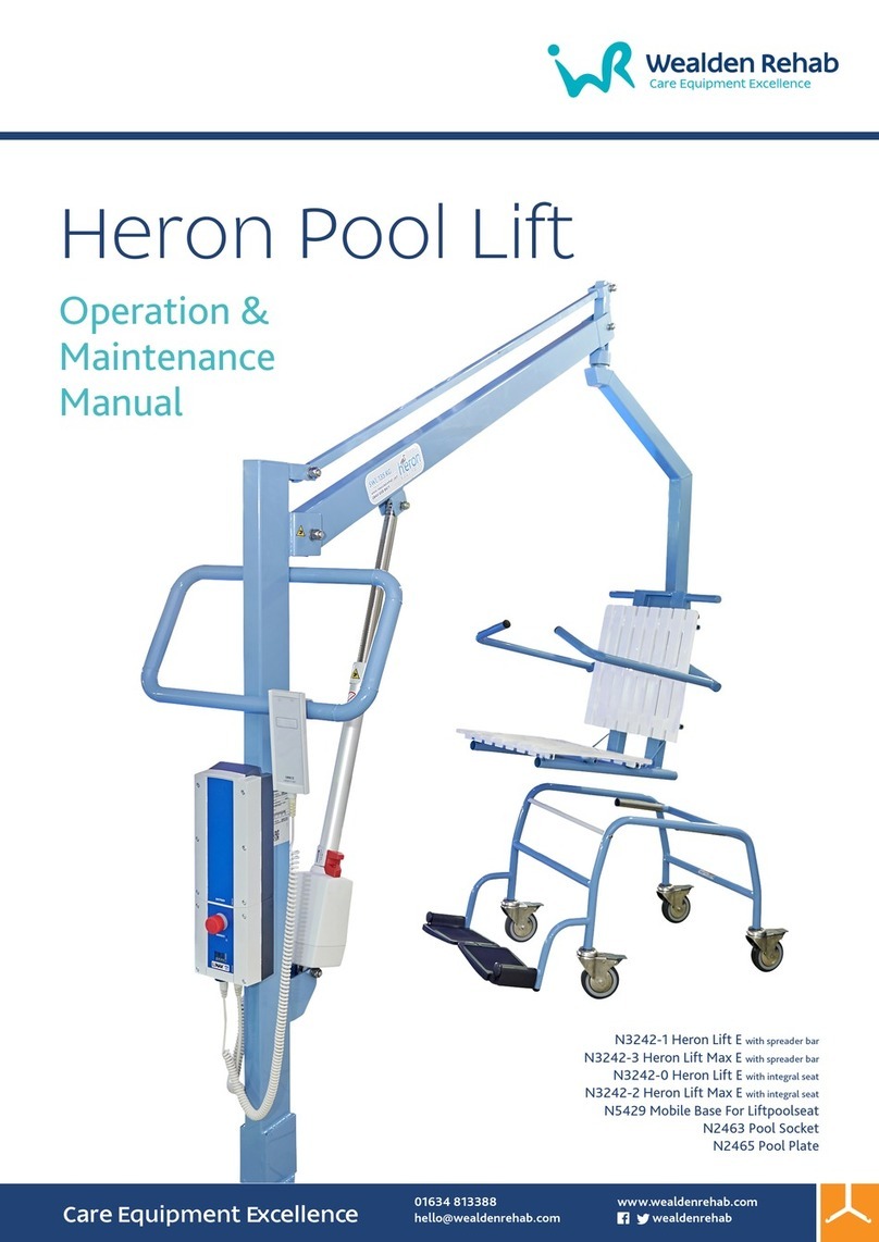
Wealden Rehab Barella User manual

INSTRUCTION MANUAL

2

3
List of contents
GENERAL INFORMATION ............................................. 5
1.1 CONTACT WEALDEN REHAB--------------------------------------5
2.2 INTENDED USE ------------------------------------------------------5
2.3 USERS ------------------------------------------------------------------5
2.4 GROUPS OF PATIENTS AND CLINICAL CONDITIONS -------5
2.5 APPLIED PARTS ------------------------------------------------------5
2.6 ENVIRONMENT OF USE -------------------------------------------5
2.8 MANUFACTURER'S DECLARATIONS ---------------------------6
WARNINGS AND USE RESTRICTIONS ........................... 6
3.1 SERIOUS ACCIDENTS -----------------------------------------------6
3.2 SYMBOLS ON LABELS AND DEVICES ---------------------------6
3.3 SYMBOLS IN THE MANUAL---------------------------------------7
3.4 SYMBOLS ON THE PACKAGING ---------------------------------7
3.5 SPECIAL WARNINGS -----------------------------------------------7
3.6 CONTRAINDICATIONS AND SIDE EFFECTS -------------------7
3.7 USE RESTRICTIONS -------------------------------------------------7
3.8 STOP/EMERGENCY FUNCTIONS (ELECTRIC VERSIONS)---8
3.9 LIST OF FREQUENTLY USED FUNCTIONS ---------------------8
AVAILABLE CONFIGURATIONS ..................................... 9
CONTENT OF THE PACKAGE AND PRODUCT
DESCRIPTION ....................................................................... 10
5.1 UNBOXING --------------------------------------------------------- 10
5.2 CONTENTS OF THE PACKAGE---------------------------------- 10
5.3 PRODUCT DESCRIPTION ---------------------------------------- 10
ASSEMBLY AND FIRST USE ..........................................10
6.1 ASSEMBLY ---------------------------------------------------------- 10
6.1.1 END RAILS AND SIDE RAILS INSTALLATION .................. 10
6.1.2 MATTRESS INSTALLATION ........................................... 10
6.1.3 WALL BATTERY CHARGER INSTALLATION .................... 11
6.1.4 FOOT SWITCH CONTROL INSTALLATION ..................... 11
6.1.5 BATTERY INSTALLATION .............................................. 12
6.2 PRELIMINARY REGULATIONS ---------------------------------- 12
6.3 FIRST USE ----------------------------------------------------------- 12
USE ............................................................................ 12
7.1 WARNINGS BEFORE USE---------------------------------------- 12
7.2 USE OF THE DEVICE ----------------------------------------------12
7.2.1 ADJUST HEIGHT AND TILT USING THE HANDSET ......... 12
7.2.2 ADJUST HEIGHT WITH FOOT SWITCH COMMAND .......13
7.2.3 ADJUST HEIGHT IN HYDRAULIC VERSIONS ................... 13
7.2.4 ADJUST TILT MANUALLY .............................................. 13
7.2.5 OPEN SIDE RAILS .......................................................... 13
7.2.6 FOLD END RAILS ........................................................... 14
7.2.7 ADJUST THE BACKREST ................................................ 14
7.2.8 TRANSPORT AND BRAKES ............................................ 14
7.2.9 TRANSFER THE PATIENT ...............................................15
7.2.10 WASHING ..................................................................... 15
7.2.11 BATTERY REPLACING AND CHARGING ......................... 16
ACCESSORIES ............................................................. 17
MAINTENANCE AND SERVICE LIFE ............................. 18
9.1 ROUTINE MAINTENANCE ---------------------------------------18
9.2 MALFUNCTIONS, EXTRAORDINARY MAINTENANCE AND
REPAIRS----------------------------------------------------------------------18
9.3 USEFUL LIFE --------------------------------------------------------18
CLEANING AND DISINFECTION ................................... 19
10.1 WASHING -----------------------------------------------------------19
10.1.1 FRAME ......................................................................... 19
10.1.2 MATTRESS .................................................................... 19
10.2 DISINFECTION------------------------------------------------------19
10.3 DRYING --------------------------------------------------------------19
10.4 STORAGE ------------------------------------------------------------19
DISPOSAL ................................................................... 19
TECHNICAL SPECIFICATION ........................................ 20
12.1 LABELLING ----------------------------------------------------------20
TROUBLESHOOTING .................................................. 21
MAIN DIMENSIONS ................................................... 22
14.1 LD31xx ---------------------------------------------------------------22
14.2 LD32xx ---------------------------------------------------------------22
14.3 LD33xx ---------------------------------------------------------------22
ELECTROMAGNETIC COMPATIBILITY ........................ 23
15.1 ELECTROMAGNETIC EMISSIONS ------------------------------23
15.2 ELECTROMAGNETIC IMMUNITY ------------------------------23
15.3 RECOMMENDED SEPARATION DISTANCES ----------------24
WARRANTY ............................................................... 25
16.1 GENERAL CONDITIONS ------------------------------------------25
16.2 REPAIRS UNDER WARRANTY-----------------------------------25

4
16.3 OUT-OF-WARRANTY REPAIRS --------------------------------- 25
16.4 NON-DEFECTIVE PRODUCTS----------------------------------- 25
16.5 HOME REPAIRS---------------------------------------------------- 25
16.6 SPARE PARTS------------------------------------------------------- 25
MAINTENANCE AND SERVICE RECORD SHEET ............ 26

5
GENERAL INFORMATION
This manual contains information for practical, correct and
safe use of the device and is intended for reading by
specialised personnel and the user of the product. It is
recommended that you read the entire manual carefully
before using the product.
If you have any doubts or need clarification, please
contact your dealer who will be able to advise you
correctly.
The importance of reading and understanding the user
manual is highlighted on the product by the following
symbol:
1.1 CONTACT WEALDEN REHAB
113 Hopewell Drive, Chatham, Kent ME5 7NP
+44 (0)1634 813388
https://wealdenrehab.com
hello@wealdenrehab.com
PRODUCT DESCRIPTION AND
INFORMATION
2.1 DESCRIPTION
Shower trolleys ideal for hygiene care to recumbent
patients, in environments such as medical facilities, care
homes, rehabilitation and geriatric units.
They must always be used under the supervision of an
attendant who has read and understood the entire
content of this manual.
The whole frame was treated with a special anti-corrosion
process, the patient platform is made of ABS plastic; side
rails and fasteners are in stainless steel, and castors are
washable.
In some versions the platform can be tilted up to 5° by
means of a gas spring to allow water to run off easily and
up to 12° head side to allow Trendelemburg function. They
are equipped with folding safety side rails and a
comfortable mattress upholstered in waterproof fabric.
Some models have a large backrest end that can be
adjusted using a servo-assisted gas spring system. The
platform height can be adjusted using an electric actuator
powered by rechargeable battery using an handset, or a
foot pedal-operated hydraulic actuator.
2.2 INTENDED USE
Trolleys for Hygienic operations over patients.
The use of the device for purposes other than
those defined in this manual is prohibited.
The manufacturer declines any responsibility
for damage to persons or property resulting
from improper use of the device or in any
case other than that provided for in this
manual.
The manufacturer reserves the right to make
changes to the product and the manual
without prior notice in order to improve its
characteristics and performance.
2.3 USERS
Nurses, professional caregivers, clinical operators, doctors,
physiotherapists, and therapists.
It is up to the specialist to judge the physical
fitness of the patient for whom the product is
intended to be used.
Use under operator supervision is always
mandatory.
2.4 GROUPS OF PATIENTS AND CLINICAL CONDITIONS
There are no particular categories of patients that can be
excluded if not patients who show evident conditions of
impossibility of personal hygiene operations (shower,
preparing).
2.5 APPLIED PARTS
The applied parts of the device are: the mattress, the side
rails, the ABS platform and the frame that supports the
platform and the mattress. Usually the contact of the
patients with the mattress is daily and up to 45 minutes per
session, with more than 10% of the body surface and more
than 10% of the head, and patients can be children, so
choose carefully the water temperature to use and below
40°C.
2.6 ENVIRONMENT OF USE
Clinical/hospital environment. Use on flat, stable and
obstacle-free surfaces. Not for outdoor use.
Application environment of type 5: outpatient care
administered in hospital or other medical centre under
medical supervision, in which the EM devices are provided
for the needs of sick people who have suffered injuries or
are carriers of disability, for the treatment, diagnosis and
monitoring.
Ambient
Temperature
Relative
Humidity Range
Atmospheric
Pressure
5˚C ~ 70˚C 20%~80% 700hPa~1060hPa
altitude ≤ 3000 m
When the patient is on the trolley, the
mattress temperature shall not exceed 40°C
2.7 STORING
Store in a dry place at room temperature. Avoid excessive
pressure and contact with discolouring materials. Avoid
excessive exposure to direct sunlight.

6
Ambient
Temperature
Relative
Humidity Range
Atmospheric
Pressure
5˚C ~ 70˚C 25%~85% @30°C
without
condensing
700hPa~1060hPa
altitude ≤ 3000 m
2.8 MANUFACTURER'S DECLARATIONS
The manufacturer declares that:
- the device is not a measuring instrument
- the device is not intended for clinical investigation
- the device is not sterile and is not for single use
- for a correct functioning and for the safety of the
user, it is necessary that the ordinary maintenance
operations are carried out as described in the
relevant paragraph.
- the device cannot be used for purposes other than
those stated in this manual
WARNINGS AND USE RESTRICTIONS
Always refer to this manual for proper use of the device.
- Store the device in an environment that complies with
the labels on the packaging and the specifications in
this manual.
- The useful life of the product is 10 years in accordance
with the correct execution of the ordinary
maintenance operations provided for in this manual. It
is strictly forbidden to use the device beyond its stated
useful life. At the end of its useful life, it is possible to
proceed as described in the relevant paragraph
- The manufacturer shall not be liable, to the fullest
extent permitted by applicable law, for any direct or
indirect, special, incidental or consequential damages
caused by:
oWrong use of the device
oImproper use of the device and outside of its
intended use
oUse of the device beyond the stated service life in
this manual
oUsing the device in environments not covered by
this manual
oUse with unsuitable patients
oThe distraction of operators or incorrect
application of commands and adjustments
oUse without checking the status of the device as
described in the relevant paragraph
oIncorrect maintenance or lack of maintenance
oUse with parts or accessories that are not
compatible or not approved by the manufacturer
oIncorrect disposal or disposal is other than as
described in this manual.
The device is equipped with labels to draw attention to
particular dangers such as:
Hand
crushing
hazard
Foot crushing
hazard
General
Warning
Electric
shock hazard
3.1 SERIOUS ACCIDENTS
In the event of serious accidents involving the
device, the user is required to promptly notify
the manufacturer and the competent
authority of the member state in which the
device is installed.
3.2 SYMBOLS ON LABELS AND DEVICES
Follow the instructions for use
Applied part type B
CE certified
Dispose of properly
Manufacturer
Manufacturing date
Indoor use only
Electrical safety class 2
CAUTION / WARNING
The warning messages inform the user
of the risk of accidents or hazards if,
during operation or maintenance
operations, the procedures and
conditions indicated are not carefully
observed.
ELECTRIC LIFTING OF PATIENT PLATFORM
(AC0039).
This symbol is present on the hand
control. Keeping the button pressed,
the patient platform is electrically lifted.
ELECTRIC LOWERING OF PATIENT
PLATFORM (AC0039)
This symbol is present on the hand
control. Keeping the button pressed,
the patient platform is electrically
lowered.
LOW BATTERY (AC0039)
This symbol is present on the hand
control. When it lights orange,
accompanied by a sound, it indicates
that the battery is running low.

7
ELECTRIC LIFTING OF PATIENT PLATFORM
(AC0083)
This symbol is present on the
multipurpose control. Keeping the
pedal pressed in correspondence to
this symbol the patient platform is
electrically lifted.
ELECTRIC LOWERING OF PATIENT
PLATFORM (AC0083)
This symbol is present on the
multipurpose control. Keeping the
pedal pressed in correspondence to
this symbol the patient platform is
electrically lowered.
BATTERY CHARGE LEVEL
The battery charge level is indicated on
the control unit, each rectangle
corresponds to 25% of the charge.
When you arrive at less than 25% it is
recommended to recharge the
battery, while when you approach 0%
STOP label will be shown
3.3 SYMBOLS IN THE MANUAL
Warning!
3.4 SYMBOLS ON THE PACKAGING
Fragile
Recyclable
Keep dry
Keep this side at the top
Do not use sharp blades to open
3.5 SPECIAL WARNINGS
Don’t use device when the working load
exceeds the stated capacity.
Don’t use with the patient unattended and/or
with side rails down.
Don’t use when the Patient and/or equipment
are not stable enough.
Don’t use full of water. The drain plug must be
closed only to not to drip water during
transfers.
Don’t use if castors are not locked when
transferring the patient from/to the trolley or
during hygiene care.
Don’t use if the original product has been
modified or tampered with.
Don’t use with even only partly faulty or
defective controls and/or components .
Don’t use when incorrectly configured or
when you think it may cause damage to the
patient or user.
Do not allow any body parts to enter the
areas with moving components and/or
controls.
Remember that the Shower Trolley safe
working load don’t include any water that is
retained within the mattress’s splash sides.
Each cm of water will result in about 10kg or
more of weight in excess.
Do not use water hotter than 40° C.
Do not use pressurized water jets
For electric versions:
Do not use the equipment in oxygen rich
environments: explosion or fire hazard
Do not use the appliance in the presence of
flammable agents: fire hazard.
To recharge the batteries, connect them to
an electrical system that complies with current
Regulations.
Do not pour any liquids on the equipment's
electrical components.
Do not damage electric wires: avoid
squashing, do not disconnect the various
plugs by pulling directly on the wire.
Perform frequent checks on the state of
electric wires and ask for them to be replaced
if in doubt.
Do not use the electrical controls continually,
but perform the duty cycles as specified in the
: “Technical Specifications” chapter.
Preserve battery life by disconnecting it when
not used for a long time.
Remove the battery before performing any
work on the equipment's circuits.
The device can be influenced by other
devices in the same environment of use by
electromagnetic interference. See par. 15 for
more details
The device can influence the other devices
present in the same environment of use by
electromagnetic interference. See par. 15 for
more details
3.6 CONTRAINDICATIONS AND SIDE EFFECTS
No particular side effects or contraindications are known.
Always read the warnings before use.
3.7 USE RESTRICTIONS
Always connect to a water drain when performing hygiene
operations.
Foam rubber castors and plastic components may burn if
they come in contact with naked flames.
Corrosive and/or abrasive detergents may damage the
upholstery and paint.
Water with a chloride or sulphide content exceeding the
amounts allowed by the law may result in increased
corrosion. Always check the suitability of patients before
use.

8
Always respect the Safe Working Load. Remember that
safe working don’t include water that is retained within the
mattress’s splash sides.
LD31xx MODELS
MAX PATIENT
WEIGHT
150 kg
SAFE WORKING
LOAD
170 kg
LD32xx MODELS
MAX PATIENT
WEIGHT
180 kg
SAFE WORKING
LOAD
200 kg
LD33xx MODELS
MAX PATIENT
WEIGHT
225 kg
SAFE WORKING
LOAD
245 kg
3.8 STOP/EMERGENCY FUNCTIONS (ELECTRIC VERSIONS)
Emergency stop: In case of problems, malfunctioning
during electrical height adjustment or any other
emergency, press the red button to arrest movement.
After any hazard situation has been removed, rotate the
red button to reactivate movement.
Electric emergency descent: In case the electric lifting stop
to work for any reason, the platform can be lowered at any
time by pressing the “EMERGENCY” ↓button with a pointed
object. The device only operates when the battery is
charged and connected.
3.9 LIST OF FREQUENTLY USED FUNCTIONS
The functions of the shower trolleys used most often are
listed below. Refer to the respective paragraphs where the
functions are explained in detail:
•Adjustment of the patient platform. See par. 7.2.1
and 7.2.2 for the electric versions and 7.2.3 for the
hydraulic versions
•Inclination of the patient platform for water
drainage: See par. 7.2.4
•Inclination of the patient platform to reach the
Trendelemburg position: See par. 7.2.4
•Battery removal and recharge: see par. 7.2.11
•Re-inserting the battery: See par. 7.2.11
•Adjustment of the side rails: see par. 7.2.5
•End rails adjustment: see par. 7.2.6
•Backrest adjustment: see par. 7.2.7
•Patient transfer: see par. 7.2.9
•Patient washing: see par. 7.2.10
•Transport and brakes: See par. 7.2.8

9
AVAILABLE CONFIGURATIONS
The product is available in various configurations that differ
from each other in:
- Type of target patient
- Platform size and side rail type
- Height adjustments and workload
- Types of wheels
The product code, shown on the product label, is used to
identify all the characteristics of the device configuration.
You can ll in the code below so as to have a quick
reference regarding the configuration of the product
purchased
L D 3
1 2 3 4 5 6 7 8 9
POSITION 1-2-3
They indicate the family model of the trolley
LD3 Shower trolleys
POSITION 4
Series, based upon target patient anatomy
SERIES SWL [kg]
1 Paediatric use 170
2 Adult use 200
3 Bariatric use 245
POSITION 5
Indicates the type of control for height adjustment
CONTROL
C Hydraulic with double pedal
D Electric with hand control
G Electric with foot switch on its holder
POSITION 6
Patient platform inner width
AVAILABLE INNER WIDTH
1 60cm
2 68cm
3 80cm
POSITION 7
Available platform length due to adjustable end rails (head
and foot side)
PLATFORM LENGTH END RAILS
1 188cm Fixed
2 203cm Head partially folding (40°)
3 218cm Both partially folding (40°)
POSITION 8
Adjustable backrest
BACKREST
1 Fixed, non-folding
2 Folding
POSITION 9
Wheels type and braking system
1 Ø 12.5cm with individual brake system
2 Ø 15cm with centralized brake system

10
CONTENT OF THE PACKAGE AND
PRODUCT DESCRIPTION
The product is delivered in a suitable cardboard
packaging so that it can be received intact and
functional.
5.1 UNBOXING
To open the package and remove its contents, pay
attention to the warnings and symbols on the package
itself. The shower trolley are supplied with the mattress
upside down and the end rail (head and foot side)
mounted at reverse; before use it is necessary to restore
them in the position of use following the assembly and first
use instructions.
The equipment is heavy: transport, unboxing
and commissioning operations must be
carried out by several people
Pay attention while remove protections with
scissors, some of them could have elastic
effect
Remove the plastic protections and all cable ties that are
used to secure the content so that it’s not damaged during
transport. Dispose of the packaging and the waste
material in an appropriate manner and follow the
instructions in the packaging and in this manual.
5.2 CONTENTS OF THE PACKAGE
The package contains
- This Instruction manual
- Product already assembled with mattress upside down
and end rails reverse mounted
- Drain kit
- Wall battery charger (only for electric versions)
- End rail blocking clamp (for the tilting end rail versions)
- Screws and spanners (as needed)
5.3 PRODUCT DESCRIPTION
1Mattress 5Backrest
2Wheels with brake 6Side rails
3Drain Hose 7Platform
4End Rails
FOR HYDRAULIC VERSIONS:
8Hydraulic piston 9Pedals
FOR ELECTRIC VERSIONS:
10 Battery 12 Electric actuator
11 Control box
13 Hand control 14 Multipurpose
ergonomic control
ASSEMBLY AND FIRST USE
6.1 ASSEMBLY
The device is delivered assembled. Pay attention to the
mattress upside down and the end rail (head and foot side)
mounted at reverse. Follow the instruction 6.1.1 and 6.1.2
before use.
Do not use the device before all items are
correctly installed and adjusted
6.1.1 END RAILS AND SIDE RAILS INSTALLATION
For the fixed end rails, unscrew with the provided spanner
the two fastening screws that block the end rail, remove
the latter from the bottom and insert it from the top, then
tighten the screws again:
For the folding end rails, rotate the rail until in a vertical
position, place the provided two blocking clamps and
secure them using the screws.
6.1.2 MATTRESS INSTALLATION
Please follow this step to correctly install the mattress.

11
Take the provided drain kit.
1. Couple the drain hose to the female drain connector.
Two seals are provided to be inserted between the
drain hose and the female drain connector. If one
suffices on its own, keep the second as a spare part
2. Place the mattress so that the blocking clamps are at
the bottom
3. Insert the male drain connector into the hole in the
mattress from above, along with the thin white gasket
and screw the drain hose on it from below after inserting
the spacer gasket
4. Use the plastic spanner to tighten the female drain
connector and subsequently insert the plug.
Centre the mattress on the trolley and check that the two
clamps underneath the mattress fit into the slots in the
plastic panel.
6.1.3 WALL BATTERY CHARGER INSTALLATION
The electric versions are also equipped with a wall battery
charger.
The battery charger is equipped with a stainless steel metal
bracket. Install it according to the environment and the
wall where it is placed. If it is a concrete wall, use two 6mm
plastic raw plugs with a screw preferably made of stainless
steel.
The battery charger must be installed in a
position where a current socket is available in
the range of the power cord and in a way
that the power cord is easily disconnected in
case of necessity.
Connect battery charger on a compliant
electrical system
Plug only on mains that respect the voltage
indicated on the battery charger
Use the following measures for positioning the holes
(drawing not in scale):
Position the holes as vertically as possible using a plumb
line. Once the raw plugs have been inserted, tighten the
screws leaving a few millimetres before tightening
completely and hook the bracket from above with sliding
movement. Tighten the screws to lock the bracket. Insert
the plug into the socket. Insert battery on the charger. The
battery comes attached to the control unit.
Batteries must be fully recharged before use.
6.1.4 FOOT SWITCH CONTROL INSTALLATION
The electric versions equipped with foot switch control
AC0083, have the possibility to position the pedal control in
different places of the frame.
The foot switch must be fixed on its fixing ange AC0575 as
shown in the following figure:
To install the xing flange or move it to another point of the
frame, unscrew the two screws on the front part until the
back of the support is removed. Hook the support at any
point on the frame, compatibly with the length of the cable
and with the visibility of the control unit. Reposition the rear
part of the support and tighten the front screws.
After choosing the position, twist the excess cable on the
cable holder underneath the xing ange. Then use the
supplied data cable adhesive holders to guide the cable
path to the control box so that the patient platform
movement does not cause it to be crushed:

12
The control must be positioned in such way
that the wiring isn’t crushed by moving parts,
using the supplied plastic supports to guide the
cable route
The control must be positioned in such way
that the operator has always at hand the red
emergency button present on the control unit
during the activation of the control.
6.1.5 BATTERY INSTALLATION
Make sure the battery is fully charged. Pick the battery from
the charger pulling the release handle and sliding the
battery. Use both hands to have better control since
battery is quite heavy. Insert the battery by sliding it on the
steel guide towards the control box on the shower trolley,
make sure the handle clicks into position:
6.2 PRELIMINARY REGULATIONS
Place the shower trolley in the working position and check
that is on a stable surface. Use brakes to stop the trolley in
a given position. Make sure that battery is fully recharged
before use.
6.3 FIRST USE
Before proceeding with the first use, it is necessary to read
this instruction manual.
Make sure that the product corresponds to what is
described in this manual and that the contents of the
package coincide with what is described in the relevant
paragraph.
Before using the product for the first time:
- Make sure there are no more components of the
device inside the packaging (screws, nuts, etc.)
- Make sure there are no obvious signs of damage or
tampering
- Check the rotation and sliding of the wheels
- Make sure there are no obvious signs of loosening of
the screws
- Fully charge the battery (only electric models)
- Insert the battery to the control unit and check It’s
functionality by lifting the platform.
USE
7.1 WARNINGS BEFORE USE
Before each use make sure that:
The product does not show any obvious signs
of tampering or damage
The product has been sanitised in the parts in
contact with the patient
The physical and clinical condition of the
patient has been assessed and found to be
appropriate for the use of the device.
The operating environment is in accordance
with the provisions of this instruction manual.
There are no particular hazards in the areas
around the device (shelves, obstacles,
flammable materials, etc. ...)
The battery is charged (only electric models)
The patient cannot operate the controls
voluntarily or accidentally
7.2 USE OF THE DEVICE
7.2.1 ADJUST HEIGHT AND TILT USING THE HANDSET
For electric versions is possible to adjust height with the
hand control.
For the LD31xx and LD32xx model, there are only 2 buttons
(soft membrane key):
Press continuously the UP button to lift the patient platform
or press DOWN button to lower the platform. Releasing the
buttons immediately stop the movement.
Keep the feet away from the points in which
the central part of the mobile frame is inserted
in the basic structure.
During electric height adjustment operations,
the operator must be in the vicinity of the red
emergency button that can be pressed in
case of necessity
For the LD33xx model there are 4 button:
To adjust height press continuously the UP button to lift the
patient platform or press DOWN button to lower the
platform.
To adjust tilt press continuously the HEAD button to tilt the
patient platform positively (head up) or press FEET button to
tilt the platform negatively (feet up). When tilting the

13
platform, each time the platform is perfectly horizontal the
control unit will beep for a second and the tilt movement
pause for few seconds.
If the orange LED next to the battery symbol on the handset
lights up during height adjustment, and an acoustic signal
is heard at the same time, the battery is running low and it
is advisable to recharge it.
To get a clearer indication of the battery charge status, see
the number of tracks present on the control unit display:
7.2.2 ADJUST HEIGHT WITH FOOT SWITCH COMMAND
The electric versions LD31 and LD32, except from the
bariatric version LD33 with column lift, have the possibility to
choose the foot switch control instead of the handset
control. This command can be operated with the feet
according to the point chosen during installation.
To adjust height press continuously the UP button to lift the
patient platform or press DOWN button to lower the
platform.
Keep the feet away from the points in which
the central part of the mobile frame is inserted
in the basic structure.
During electric height adjustment operations,
the operator must be in the vicinity of the red
emergency button that can be pressed in
case of necessity
7.2.3 ADJUST HEIGHT IN HYDRAULIC VERSIONS
To adjust height on the hydraulic versions, pump the pedal
lever down with the foot several times to lift the platform,
until the desired height is reached.
To lower the platform, lift the lever with the foot until the
desired height is reached.
Keep the feet away from the points in which
the central part of the mobile frame is inserted
in the basic structure.
7.2.4 ADJUST TILT MANUALLY
On LD31 and LD32 models, both electrical and hydraulic,
it’s possible to tilt the patient platform in order to reach
Trendelenburg position (feet up) or water drain position
(head up). To tilt patient platform hold the side rail or, in the
versions with tilting end rails, the frame. Push the adjustment
release lever upwards and tilt the platform.
Disengage the release lever once the desired inclination
has been reached.
During tilt adjustments the patient must lie
down
Make sure that during tilt adjustment the
moving parts do not collide with adjacent
masses
During transport and washing the shower
trolley must be as planar as possible
7.2.5 OPEN SIDE RAILS
On all models the side rails can be opened in order to
transfer the patient from the bed. To open the side rail, lift it
with two hands and tilt it outwards. Accompanies the rail
until is totally lowered.

14
To close the side rails repeat the operations at reverse,
return it to the vertical position until it clicks into position.
Check that the rail is well placed before leaving it.
Keep the side rails closed when the patient is
on the mattress
7.2.6 FOLD END RAILS
On some models end rails are partially folding, about 40° tilt
angle. To fold the end rail lift it with two hands and tilt it
outwards, until the end position is reached.
To close the end rails repeat the operations at reverse,
return it to the vertical position until it clicks into position.
Check that is well placed before leaving the rails.
7.2.7 ADJUST THE BACKREST
The versions LD31 and LD32 with tilting backrest are fitted
with a gas spring to adjust the tilt angle of the backrest up
to +63°.
Pull the backrest adjustment lever upwards and with the
other hand guide the platform into the desired position.
Keep hands away from the points in which
the backrest crosses the side rails and from
the point in which the backrest sit on the
metal frame
7.2.8 TRANSPORT AND BRAKES
The shower trolley is equipped with pivoting wheels to allow
manoeuvres in confined spaces; depending on the drive,
the total brakes or the directional brakes are activated,
which facilitates straight paths. During transport, the shower
trolley must be positioned horizontally to avoid patient
movement. The height of the platform is not relevant but it
is preferable to keep a height that gives the operator
comfort while pushing the stretcher but that does not
affect the visibility of the path.
Parking brakes must be activated when
transferring patient from the bed onto stretcher
and when washing the patient
The directional lock does not act as a brake, to
brake the trolley use the parking brake
Do not push the trolley sideways when the
directional lock is on
7.2.8.1 CENTRALIZED BRAKES
On the models with centralized brakes, the castor brakes or
the directional lock are applied simultaneously to the most
near wheels. With the pedal in horizontal position, the brake
is disengaged and the four castors can roll and swivel freely
in all directions.
By pushing with the foot the pedal downwards on the outer
side, pointed out by a red dot, the two most near castors
lock simultaneously for all directions.
To lock all 4 wheels, it is necessary to act on the brake both
on the foot side and on the head side of the shower trolley.
By pushing downwards the pedal on the inner side, pointed
out by a green dot, the wheels on that side is prepared to
lock in the direction of travel.
By pushing the stretcher from the head side, the wheel is
automatically positioned and locked on the straight

15
direction. With the inserted directional block, it is easier to
proceed in a straight line. To disengage the brake or
directional lock is necessary to put back the lever in
horizontal position.
7.2.8.2 INDIVIDUAL BRAKES
On the models with individual brakes, each wheel has its
own brake, except for one wheel that has the directional
lock. To insert the brake, push downwards with the foot the
red lever down on the outermost part. The same operation
is valid for directional lock: push downward the green lever.
To disengage the brake push the red lever downwards on
the innermost part. The same for the green lever to
disengage the directional lock.
7.2.8.3 TRANSPORT
Move the trolley by holding the foot end rail or the head
end rail after releasing all the brakes.
To go through 80 cm-wide doorways, pull the side rails
inwards while passing through the door: they will go back
to their original position when released.
Do not push the trolley sideways when the
directional lock is on.
During patient transport the side rails must be
closed and the patient must lie down. The
platform must be as planar as possible.
Transport can be done only manually, DON’T
use motor vehicles
7.2.9 TRANSFER THE PATIENT
To transfer the patient from bed to the trolley and vice
versa, is possible to use a suitable harness or is possible to
use the rolling technique. In the latter case, open one side
rail of the bed and open one side rail of the shower trolley
in order to get the head side of the trolley aligned with the
head side of the bed. Get as close as possible to that side
of the bed with the open side of the shower trolley.
Adjust the trolley height so that the height of the platform is
at the same level of the bed mattress. Help the patient to
lay on the opposite side of the bed. Activate the brakes.
Help patient to roll onto the stretcher mattress.
Complete the transfer and unlock the wheels to step away
from the bedside so you can close the side rail. Special
transfer sheets that reduce friction between surfaces can
be used to improve transfer comfort.
7.2.10 WASHING
When the washing location is reached, the park brake
should be engaged as soon as possible.
7.2.10.1 PREPARE THE DRAINAGE
The hose attached to the mattress will drain the water
during the patient washing, so before proceeding, make
sure the hose is not obstructed. Place the hose end in the
floor drain or toilet and open or remove completely the
plug.
Remove completely or open the plug to avoid
water accumulation and avoid the creation of
an hazardous situation for the patient.

16
An excessive water volume would lead to
aggravate the permitted load of the trolley
and could drown the patient.
Brake the wheels to avoid the movements of
the stretch during the washing
7.2.10.2 WASH
Before washing, make sure that the plug is open or
removed, that the wheels are braked. During washing, the
shower trolley must be positioned horizontally to avoid
patient movements or water accumulations. The height of
the platform is not relevant but it is preferable to keep a
height that gives the operator a comfort during the
washing operations. The side rails must be closed and
locked.
Do not use water hotter than 40° C.
Do not use pressurized water jets.
Do not direct any water jets at electrical parts
Remember that the Shower Trolley safe
working load (SWL) don’t include any water
that is retained within the mattress’s splash
sides. Each cm of water will result in about
10kg or more of weight in excess.
7.2.10.3 END OF WASH AND EXCESS WATER DRAINAGE
At the end of the shower is possible to remove water
excess. The shower trolleys has the tiltable platform so that
water can easily run off. Refer to chapter 7.2.4 to activate
platform tilt. Once all the water has come down from the
drain hose is possible to proceed to replace the plug, close
it, and put the tube in the transport position.
7.2.11 BATTERY REPLACING AND CHARGING
Battery charge status can be always monitored trough the
battery indicator present on the control box. Each vertical
rectangle is a charge level of 25%. So The charge level will
go from 100% to 0% by passing 4 step:
100% 75% 50% 25%
When the charge level is 25%, a plug icon is showed to warn
the user to charge battery. When charge level is 0%, a STOP
text is showed and no more operation is possible.
To remove battery, pull the release handle and slide to left.
Use both hands to remove the battery since is quite heavy.
Replace the battery preferably when the
patient is not in the nearby.
Do not touch the contacts of the battery
or battery chargers and the patient or
any other accessible parts
Do not immerse the battery in liquids, do
not invest the electrical parts with direct
water jets
Put the battery on the provided wall battery charger and
let battery to fully charge (about 8 hours).
When the orange led turn off, the battery is fully charged.
Then remove battery and put it back on the control box. To
ensure that the shower trolley is fully operational at all times,
we recommend purchasing a spare battery.
The battery charger is designed to automatically adapt to
voltage and frequencies between 100-240V~/ 50-60Hz and
is provided with an automatic safety charge limiter.
Batteries do not require any other maintenance.

17
ACCESSORIES
A wide range of accessories can be applied to
Barella Shower Trolleys, contact Wealden Rehab
https://wealdenrehab.com/contact-us
Use only official Barella accessories.
AC0071 - RECHARGEABLE BATTERY 24V
Spare battery
AC0318 - BATTERY CHARGER
Supplied on request with
international cable. Used to
recharge the battery by
connecting it to the mains
AC0575 - SUPPORT FOR BUTTERFLY PEDAL
Can be applied on both sides of
the base. Used to house
accessory AC0083
AC0039 – HANDSET
Handset with magnet to be
attached to any point of the
frame
AC0083 – ADDITIONAL MULTIPURPOSE CONTROL
For use with hand or foot, with
magnetic or with support
(AC0575)
AC0892 – DRAIN KIT
Drain kit with female and male
drain connector, plug and hose
length 150cm
AC0574 – BACKREST EXTENSION
The device makes it possible to
increase the length of the
adjustable backrest. Only
applicable for versions with
adjustable backrest and partly
folding head end
AC0578 – SAFETY DEVICE
Block any inappropriate use
when the caregiver is away
AC1126 – SHOWER MATTRESS STRAPS
Set of straps for block the
shower mattress to the side rails
and to the end rails. The set is
made of 2 short straps with clips
for long sides and 2 long straps
for short sides
AC0838 – IV POLE
The IV pole is provided with a
supporting stand made of
stainless Steel. This support can
be adjusted as to its rotation
and height. Pole
dimensions: 110 x 23,5 cm.
Support dimensions: 28 x 2 cm
AC1237 – SOFT SEMI CYLINDRICAL CUSHION
Pillow with the same fabric of
the soft mattress. Dimensions
55x15x7cm
AC1236 – SOFT WEDGE CUSHION
Pillow with the same fabric of
the soft mattress. Dimensions
55x55x14cm with inclination of
15 °
SP0041 – SOFT SHOWER MATTRESS - S
SP0035 – SOFT SHOWER MATTRESS - M
SP0042 – SOFT SHOWER MATTRESS - L
Soft Shower Mattress inside
dimensions:
S: 60x160cm
M: 68x188cm
L: 80x188cm

18
For accessories compatibility please follow this table
ACCESSORIES LD31 LD32 LD33
FOR ELECTRIC VERSIONS
AC0071 RECHARGEABLE BATTERY 24V • • •
AC0318 WALL BATTERY CHARGER • • •
AC0039 HANDSET • •
AC0575 SUPPORT FOR BUTTERFLY
PEDAL
• •
AC0083 ADDITIONAL FOOT CONTROL • •
AC0578 SAFETY DEVICE • •
FOR PATIENT COMFORT
AC1236 SOFT WEDGE CUSHION • • •
AC1237 SOFT SEMI CYLINDRICAL
CUSHION
• • •
AC0574 BACKREST EXTENSION •*
OTHER ACCESSORIES
AC0838 IV POLE • • •
AC0892 DRAIN KIT • • •
AC1126 SHOWER MATTRESS STRAPS • • •
SP0041 SOFT SHOWER MATTRESS - S •
SP0035 SOFT SHOWER MATTRESS - M • •
SP0042 SOFT SHOWER MATTRESS - L • •
*Models LD32xx22
MAINTENANCE AND SERVICE LIFE
9.1 ROUTINE MAINTENANCE
Scheduled maintenance is required for proper operation
of the device, proper use, patient and operator safety, and
performance assurance of the device.
Check the equipment whenever it has undergone "rough
treatment" (e.g.: fall, liquid spill, etc.) and whenever any
doubts arise concerning its safety.
Ordinary maintenance work may be carried out by
specialised operators or authorised technical personnel.
PERIODICITY CATEGORY VERIFICATION
6 months
Visual
inspection
of the
device
The integrity of mattress,
absence of holes and cuts
Frame integrity and
absence of cracked
elements
Check that nut and bolts
are firmly tightened
Integrity of the four wheels
and of the braking system
Presence of the hand
control / foot control and
integrity
General cleaning of the
device
Absence of evident
deformations on the frames
No friction noise or
abnormal vibration during
adjustments
Check that the connectors
for the controls, control unit
and actuators are fully
inserted (electrical versions)
Check the integrity of the
electrical cable insulation
(electrical versions)
Functional
verification
Checking that the height
adjustment is working
properly
Verification of tightening
Correct pivoting of the
wheels
Correct rolling of the
wheels
Check the stability of the
head section frame
Check the functionality of
the braking system
Executing a full load lifting
cycle
12-24
month
Safety
Tests
Safety tests IEC/EN62353
(electric models)
9.2 MALFUNCTIONS, EXTRAORDINARY MAINTENANCE
AND REPAIRS
Extraordinary maintenance work may only be carried out
by personnel authorised by the manufacturer. Otherwise
any warranty conditions will be immediately terminated.
The manufacturer is not responsible for any damage
caused using this product.
Any malfunctions found by the user must be promptly
reported to the distributor or directly to the manufacturer
and inhibit the use of the device.
Repairs may only be carried out by technical personnel
authorised by the manufacturer and may include the
withdrawal of the device in order to carry out the
necessary repairs.
Modifications to the device are not allowed
9.3 USEFUL LIFE
The service life of the device is defined at the beginning of
this manual. (See warning and use restrictions)
At the end of its useful life, you can proceed in the following
ways:
1) Dispose of the device as described in the
paragraph "Disposal".
2) Require the manufacturer to recondition and
recertify the device so that it can continue to be
used
As stated in the paragraph "General warnings", the
manufacturer declines all responsibility for the use of the
device beyond the useful life established in this manual.

19
CLEANING AND DISINFECTION
It is necessary to clean the device at the end of each use
if the device is intended for different users.
10.1 WASHING
After each use, the trolley must be cleaned, disinfected
and dried. It is important to store it in a dry and well
ventilated room to avoid mold and corrosion spots on
metal parts. Be careful not to damage or disconnect the
labels attached to the device. Non-aggressive detergents
may be detergents with a content of less than 5% of non-
ionic surfactants, anionic surfactants and ethyl alcohol. If
possible use products with biodegradable surfactants.
10.1.1 FRAME
Clean with a cloth or sponge dipped in non-aggressive
detergent and dry. The shower trolley can also be washed
with water from 85°C to 95°C for at least 3 minutes. Avoid
direct jets of water or other liquids onto mechanical parts
and particularly onto electrical parts.
10.1.2 MATTRESS
Wash carefully with lukewarm water and neutral
detergents. Dry before disinfecting with approved
products. The mattress can be washed with water up to
60°C for at least 3 minutes. Avoid direct jets of water or
other liquids onto mechanical parts and particularly onto
electrical parts
10.2 DISINFECTION
In general, the mattress is highly resistant to most surface
disinfectants currently in use. Autoclaving or sterilization is
not allowed.
For disinfection of the product use disinfection with a low
chlorine content, such as AMUCHINA® 10% or equivalent
solutions with a concentration of 0.1% sodium hypochlorite
and the following spectrum of action:
•bactericide in the presence of interfering
substances according to EN 1276:1997;
•a fungicide in the presence of interfering
substances according to EN 1650:1997;
•bactericidal surface test according to EN
13697:2001;
•fungicide surface test according to EN 13697:2001;
•active on Salmonella Typhimurium according to
EN 13697:2001;
•active on: HIV, HAV - HBV, HCV;
•Virucidal according to EN14476:2005;
•active on H1N1 influenza virus according to
EN14476:2005.
For safe use, refer to the instruction leaflet included in the
product.
10.3 DRYING
Adequate drying is a crucial factor in the care and
maintenance of the mattress. Dry naturally at a
temperature of up to 60°. Do not press or mangle.
10.4 STORAGE
Store in a dry area, at room temperature. Avoid excessive
pressure and contact with materials that quickly discolour.
Do not expose the mattress to direct sunlight (UV-
radiation).
DISPOSAL
The symbol on the label of the equipment
indicates that the waste must be subject to
"separate collection".
Therefore, the user must either hand over the
waste to the separate waste collection centres set up by
the local authorities or hand it over to the retailer against
the purchase of new equipment of an equivalent type.
Separate waste collection and subsequent treatment,
recovery and disposal operations promote the production
of equipment with recycled materials and limit any
negative effects on the environment and health caused by
improper waste management. Illegal disposal of the
product by the user entails the application of the
administrative sanctions referred to in Article 50 et seq. of
Legislative Decree no. 22/1997.

20
TECHNICAL SPECIFICATION
Modications to the device not allowed.
The wall battery charger is equipped with
certied power supply cable, do not
replace it, constitutes the only means of
which the charger can be isolated by the
power supply through the plug
disconnection
LD31 LD32 LD33
Height
adjustment
system
Hydraulic / Electric with
Battery
Electric with
Battery
Duty Cycle Temporary use 10% 2min use/18min
pause
IP protection X5
Power source
Batteries (24V / 2.7Ah 79x55x102h mm)
Battery Charger 100-240V - 50/60 Hz MAX
400mA
Electrical safety
Shower trolleys electrical versions: Internal
power supply 24V
Battery charger: Class II
Maximum Patient
Weight 150 Kg 180 Kg 225 Kg
Safe working load 170 Kg 200 Kg 245 Kg
Maximum patient
height 160cm 188cm 188cm
Weight 80 Kg 106 Kg
Castor diameter 12,5 cm Ø12,5 – 15
cm Ø15 cm Ø
Castor braking
system
Individually
on each
castor
Individually
on each
castor or
centralized
Centralized
Steering system No Only on
centralized Yes
Reduction space
side rails Yes
Trendelemburg tilt 12° 12° 12°
Inclination for
water draining 5° 12°
Length of drain
hose 150 cm
Reclining
Backrest
Yes, some models
maximum tilt 63° No
Use temperature 5-40°C
Use Humidity 20-80%
Use atmospheric
pressure 800-1060hPa (Maximum altitude 2000m)
Transport and
storage
environment
temperature from +5°C to +70°C
relative humidity from 25% to 85 %
atmospheric pressure from 700hPA to
1060hPa
Registration
Number Italian
Ministry of Health
1150561 1150565 1150567
CND (National
Classication of
Medical Devices
- Italy)
V0899 - CLINICAL ACTIVITY EQUIPMENTS –
OTHERS
GMDN Code and
Term
31092 - a manually-operated device
designed as a stretcher that is specially
designed for the purpose of washing a
patient whilst the patient lies upon it. It will
typically be used for patients who are
incapable of supporting themselves and
persons with a disability.
12.1 LABELLING
The following labels are present on the device and on the
packaging. All symbols are explained in par. 3.1.
On adult shower trolley (LD32xxx), electric models:
On pediatric shower trolley (LD31Cxx), hydraulic models:
On bariatric shower trolley (LD33xxx), electric models:
This manual suits for next models
1
Table of contents
Other Wealden Rehab Medical Equipment manuals
Popular Medical Equipment manuals by other brands

Stryker
Stryker Mul T Pad TP26E quick start guide

Arizant Healthcare
Arizant Healthcare Bair Hugger Ranger 247 Operator's manual

Mettler Electronics
Mettler Electronics Sonicator Plus 941 instruction manual

Buerer
Buerer PO 60 manual

Otto Bock
Otto Bock 17BK2 Series Instructions for use

Medline
Medline SwivAssist Bar user guide