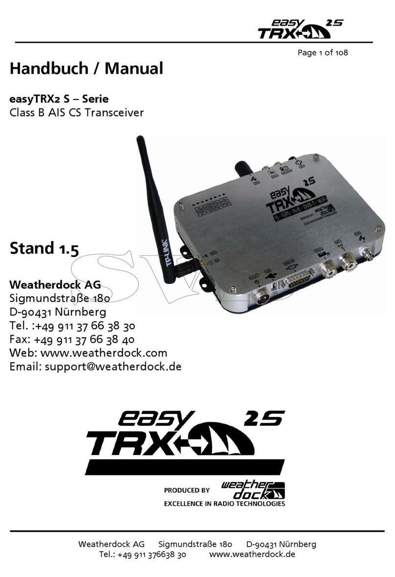
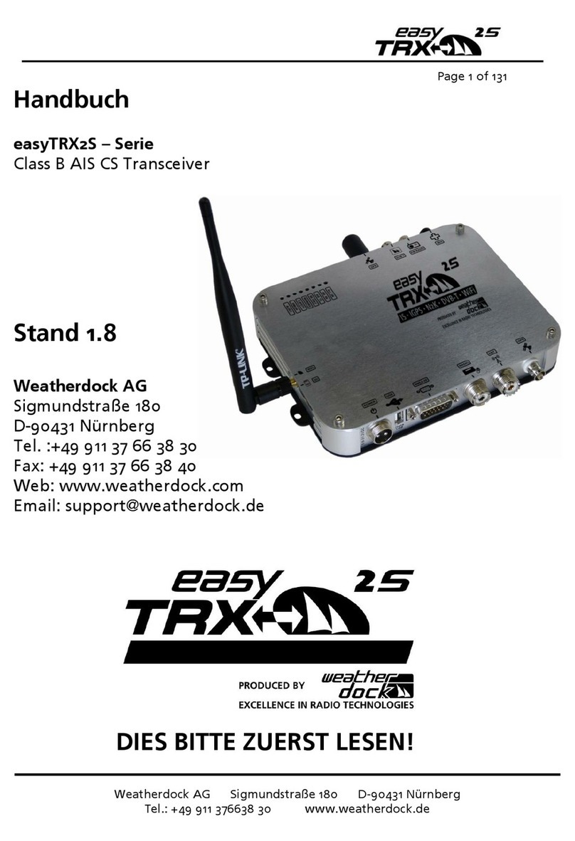
Weatherdock easyTRX2S Series User manual

Seite 1 von 68
Manual
easyTRX2S –series
Class B AIS CS Transceiver
Stand 2.3

Page 2 of 68
Seite 2von 68
General Warning
ALL MARINE AUTOMATIC IDENTIFICATION SYSTEM (AIS) UNITS UTILIZE A
SATELLITE BASED SYSTEM SUCH AS THE GLOBAL POSITIONING SATELLITE
(GPS) NETWORK OR THE GLOBAL NAVIGATION SATELLITE SYSTEM
(GLONASS) NETWORK TO DETERMINE POSITION. THE ACCURACY OF THESE
NETWORKS IS VARIABLE AND IS AFFECTED BY FACTORS SUCH AS THE
ANTENNA POSITIONING, HOW MANY SATELLITES ARE USED TO
DETERMINE A POSITION AND HOW LONG SATELLITE INFORMATION HAS
BEEN RECEIVED FOR. THEREFORE IT IS DESIRABLE WHEREVER POSSIBLE TO
VERIFY BOTH YOUR VESSELS AIS DERIVED POSITION DATA AND OTHER
VESSELS AIS DERIVED POSITION DATA WITH VISUAL OR RADAR BASED
OBSERVATIONS.
THE EASY TRX2S SOFTWARE IS INTENDED FOR USE AS AN INSTALLATION
AND CONFIGURATION TOOL. THE APPLICATION IS NOT A NAVIGATION
TOOL AND SHOULD NOT BE USED AS SUCH.
LICENSING for Class B transmitter easyTRX2S
IMPORTANT INFORMATION:
IMPORTANT: IN MOST COUNTRIES THE OPERATION OF AN AIS UNIT IS
INCLUDED UNDER THE VESSELS MARINE VHF LICENSE PROVISIONS. THE
VESSEL ON TO WHICH THE AIS CLASS B UNIT IS INSTALLED MUST
THEREFORE POSSESS A CURRENT VHF RADIOTELEPHONE LICENSE FOR THE
AIS CLASS B UNIT WHICH LISTS THE AIS SYSTEM AND THE VESSEL CALL SIGN
AND MMSI NUMBER. PLEASE CONTACT THE RELEVANT AUTHORITY IN

Seite 3 von 68
YOUR COUNTRY FOR MORE INFORMATION. IN ACCORDANCE WITH OUR
POLICY OF CONTINUAL DEVELOPMENT AND PRODUCT IMPROVEMENT THE
EASYTRX2S HARDWARE AND SOFTWARE MAY BE UPGRADED FROM TIME
TO TIME AND FUTURE VERSIONS OF THE EASYTRX2S MAY THEREFORE NOT
CORRESPOND EXACTLY WITH THIS MANUAL. WHEN NECESSARY,
UPGRADES TO THE PRODUCT WILL BE ACCOMPANIED BY UPDATES OR
ADDENDA TO THIS MANUAL. PLEASE TAKE TIME TO READ THIS MANUAL
CAREFULLY AND TO UNDERSTAND ITS CONTENTS FULLY SO THAT YOU
CAN INSTALL AND OPERATE YOUR AIS SYSTEM CORRECTLY.
Information contained in this manual is liable to change without notice.
Weatherdock AG disclaims any liability for consequences arising from
omissions or inaccuracies in this manual and any other documentation
provided with this product.
WARNINGS AND PRECAUTIONS
IT IS THE SOLE RESPONSIBILITY OF THE OWNER/OPERATOR OF THE SHIP TO
COMMAND THE VESSEL SAFELY AND TO BE IN FULL CONTROL OF ALL
OPERATING CONDITIONS DURING THE ENTIRE TRAVEL TIME. BY MISTAKEN
CONDUCT OF THE OPERATOR OF A SHIP EQUIPPED WITH A DEVICE FROM
THE EASYTRX2S PRODUCT LINE IF THE OPERATOR DOES PAY UNDIVIDED
ATTENTION TO OPERATION AND SURROUNDING CONDITION DAMAGE OR
PERSONAL INJURY MAY BE CAUSED IN THE EVENT OF AN ACCIDENT.
CAUTION
IT IS THE DUTY OF THE OPERATOR TO HANDLE THE EASYTRX2S OR ITS
DERIVATIVES WITH CARE. THE DEVICE CANNOT RELEASE YOU FROM YOUR
OBLIGATIONS OF DUE DILIGENCE!
THUS IT IS IMPORTANT AT ALL TIMES TO KEEP A
PROPER LOOKOUT.

Page 4 of 68
Seite 4von 68
THIS SOFTWARE USES COMPONENTS AND SOURCE CODE DEVELOPED BY
OTHER COMPANIES OR GROUPS.
MICROSOFT .NET FRAMEWORK V2.0: COPYRIGHT © 2005 MICROSOFT
CORPORATION
ALL TRADEMARKS MENTIONED IN THIS DOCUMENT ARE THE PROPERTY OF
THEIR RESPECTIVE OWNERS.
© 2010 WEATHERDOCK AG
COPYING OF THIS DOCUMENT AND GIVING IT TO OTHERS AND THE USE
OR COMMUNICATION OF THE CONTENTS THEREOF, IS FORBIDDEN
WITHOUT EXPRESS AUTHORITY. OFFENDERS ARE LIABLE TO THE PAYMENT
OF DAMAGES.
Responsible authority
Please find the official form you need for registration at the Federal
Network Agency for the use of an easyTRX2S Transceiver unit in Germany
as a PDF file for print out on the enclosed CD.
License number BSH:
BSH/46162/4320939/10

Seite 5 von 68
Bundesamt für Seeschifffahrt und Hydrographie (BSH)
Bernhard-Nocht-Strasse 78
D-20359 Hamburg
System requirements
The easy TRX2S programming application is designed to operate with
Microsoft Windows® 2000 (SP 3), XP (SP 2), Vista and Win 7/10.
Recommended minimum system requirements are:
•Microsoft Windows® 2000 SP3 or Microsoft Windows® XP SP2
•Display resolution of at least 1024 x 768
•At least one USB port
1WHAT IS AIS –IN A NUTSHELL................................................................. 7
1.1 EXISTING AIS STANDARDS? ..................................................................8
1.2 CONTENT OF THE “CLASS A” STANDARD: EN61993-2-2002...............8
2SCOPE OF DELIVERY ................................................................................ 11
3COMMISSIONING - OPERATING ..............................................................12
4CONNECTING SUGGESTIONS...................................................................14
5CABLE ASSIGNMENT ................................................................................15
6PROGRAMMING...................................................................................... 18
6.1 TAB: STATIC DATA .............................................................................. 18
6.2 TAB: DIAGNOSTICS.............................................................................. 20
6.3 TAB: SENT DATA.................................................................................. 24
6.4 TAB: RECEIVED DATA.......................................................................... 25
6.5 TAB: SD-CARD...................................................................................... 26
6.6 TAB: CPA-ALARM ................................................................................ 29
6.7 TAB: ANCHOR-ALARM .........................................................................31
6.8 TAB: WLAN .......................................................................................... 33
6.8.1 CONNECTION OF WIFI-ANTENNA................................................... 33
6.8.2 MORE WIFI CONNECTIONS.............................................................. 34
6.8.3 INTERNET AND AIS DATA SIMULTANEOUSLY ............................... 34

Page 6 of 68
Seite 6von 68
6.8.4 CHECKING THE CONNECTION.........................................................40
6.8.5 RESET OF WIFI SETTINGS ................................................................. 43
6.9 SOFTWARE-UPDATE............................................................................44
7IS: INTEGRATED SPLITTER ....................................................................... 47
8IGPS: INTEGRATED GPS ANTENNA.........................................................48
9IDVBT: INTEGRATED DVBT AMPLIFIER ..................................................49
10 N2K: NMEA2000 COMPATIBILITY ......................................................50
11 MOUNTING.............................................................................................. 52
11.1 DIMENSIONS OF THE EASYTRX2S....................................................... 52
11.2 VHF ANTENNA..................................................................................... 52
11.3 GPS ANTENNA ..................................................................................... 53
11.4 CONNECTION TO A PLOTTER.............................................................. 54
11.5 EXTERNAL SWITCHES .......................................................................... 54
11.5.1 SRM BUTTON ................................................................................... 54
11.5.2 SWITCH (FUNCTION SET BY SOFTWARE) ....................................... 55
11.5.3 SILENT MODE „PURE RECEIVING MODE“ ...................................... 55
11.5.4 ANCHOR ALARM .............................................................................56
11.6 EXTERNAL DEVICES (ADDITIONAL)....................................................56
11.6.1 BUZZER .............................................................................................56
11.6.2 MULTIPLEXER (NMEA-INPUT, 38400/4800 BAUD) ........................56
12 TROUBLESHOOTING ............................................................................... 57
13 MAINTENANCE........................................................................................58
14 STANDARDS.........................................................................................58
15 TECHNICAL DATA................................................................................59
16 CONTACT AND SUPPORT INFORMATION .......................................... 63
17 LICENSE AGREEMENT .............................................................................64
18 WARRANTY .........................................................................................64
19 NOTES...................................................................................................66

Seite 7 von 68
1What is AIS –In a nutshell
Substantial investment over the last few years has resulted in the fact that
transport safety systems in coastal waters are considered to be the most
modern worldwide. The introduction of AIS technology by the
International Maritime Organization (IMO) will contribute to the currently
available traffic information and thus improve navigation safety.
This data is exchanged automatically and in short intervals between AIS
devices via specific VHF transmitters and receivers.
The VHF transmitting unit transmits the data telegram via one of two
internationally defined AIS radio frequencies. One of the characteristics of
AIS technology compared to other radio services is the automatic
organization of several AIS devices on just one radio frequency without
disturbing each other.
This is achieved by the SOTDMA transmission method („Self Organizing
Time Division Multiple Access“).
The data is transmitted within one or more time-slots via the two radio
channels which are reserved for AIS devices. Each device generates its own
transmission schedule based on the observed past data traffic and the
knowledge about future actions of other AIS devices within radio range. In
this respect, the necessary time slots needed for the transmission are
occupied. The transmitted data packets are received by every ship within
radio range, which is also equipped with such a device to ensure the
transmission of the above-stated data. The dynamic ship data is transmitted
quite frequently compared to the static and journey-related data, which is
only sent at minute intervals. The transmission of data telegrams happens
automatically, in short time intervals, depending on the situation, i.e. speed
and current maneuver situation. For example, if a commercial ship lies at
anchor it only sends a message every three minutes, if it is moving and
putting about at the same time it sends at two second intervals.

Page 8 of 68
Seite 8von 68
1.1 Existing AIS standards?
The “Class A” AIS service is described in the document ITU-R M.1371-1 where
R stands for „Recommendation“.
This „standard document“ is valid for AIS data transfer with specifications
for the so-called „Class A“ and „Class B“ Service.
As mentioned previously, “Class A“ Transceivers operate with the SO-called
SOTDMA method.
The use of „Class A“ Transceivers is mandatory in the professional shipping
as they are obliged to report.
Operation of „Class B“ Transceivers is described in document EN62287. The
observation of the properties specified in the standards is obligatory for
„Class B“ Transceivers.
„Class B“ Transceivers are not mandatory and are commonly used in the
leisure boat area.
The devices of the product line easyTRX2S are „Class B“ Transceivers.
1.2 content of the “Class A” standard: EN61993-2-
2002
The telegram of a „Class A“ transmission consists of three different types
of messages:
Dynamic information:
•MMSI number
•Position of the ship (derived from GPS)
•Time, when the position was measured in UTC
•Course over ground (COG)
•Speed over ground (SOG)
•Heading (HOG)

Seite 9 von 68
•Type of vessel
•Rotational speed/turn rate
Static information:
•Call sign and name of the vessel
•Length and width of the vessel
•IMO-number of the vessel, if existent
•Type of vehicle
•Position of the GPS sensor onboard
Journey-related information:
•Draught of the vessel
•Type of cargo
•Port of destination and estimated time of arrival (ETA)
•Route plan, optional
The block of dynamic information is the most important block with regard
to threatening collisions. Therefore this block of information is transmitted
in a compulsory way, depending on the vessels movement. The following
table shows the mandatory repetition rate of the “Class A” Transceiver
linked to the ship’s movement:
anchored vessels: 3 minutes
vessels at 0 –14 kn: 10 seconds
vessels at 0 –14 kn, fast maneuver: 3.3 seconds
vessels at 14 –23 kn: 6 seconds
vessels at 14 –23 kn, fast maneuver: 2 seconds
vessels at > 23kn: 2 seconds
vessels at > 23 kn, fast maneuver: 2 seconds
The static data such as information regarding the journey is dispersed every
6 minutes.
This data is sent in turns according to the stipulated period to the one
(161.975 MHz) and subsequently to the other channel (162.025MHz).
As mentioned previously, the „Class A“ Transmitter operates with the so-
called SOTDMA method (self-organized time division multiple access).

Page 10 of 68
Seite 10 von 68
This is a „self-organized time slot allocation for telegrams, which means
that the ship listens to the radio traffic and determines the information
contained in these telegrams and on which “time slot” the own transmitter
may transmit without overriding other telegrams.
The complex SOTDMA method is replaced by a technically simpler method
CSTDMA for Class B-Transponders.
CSTDMA means „Carrier Sense Time Division Multiple Access“
At the beginning of a timeslot the Class B device
1
checks whether the
channel is occupied or not and then sends its message. This method is best
described as “listen-before-talk-method”. A “Class B” Transmitter simply
listens and then transmits on a free time slot without checking this in detail
once again or coordinating with the other participants.
The following table shows the stipulated repetition rate of a „Class B“
Transceiver depending on the speed of the ship.
Dynamic information:
boats at < 2 kn: 3 minutes
boats at > 2 kn: 30 seconds
The static data such as the information regarding the journey is dispersed
every 6 minutes. (as in „Class A“)
This data is sent in turns according to the stipulated period to the one
(161.975 MHz) and subsequently to the other channel (162.025MHz).
The above-mentioned repetition rates apply to the standard operation.
The „Class B“ Transmitter does not have its own automatism to change the
repetition rate independently, except for the above-stated values.
Authorities may in exceptional cases reduce the repetition rate to 5 seconds
or refuse admittance of the „Class B“ to the SOTDMA method (e.g. in the
case of heavy traffic) within their responsibility.
1

Seite 11 von 68
The above-stated information does not raise a claim for completeness of
contents and infallibility but rather serve as an introduction to this issue.
For more information please contact the Bundesamt für Seeschifffahrt und
Hydrografie (Federal Maritime and Hydrographic Agency) in Hamburg.
Picture 1-AIS network
2Scope of delivery
Included in delivery are:
•The corresponding device of the easyTRX2S product line
•Connection cable for power supply, Length: 1,5m
•Data transfer and external switches cable, Length: 2,4m
•User’s manual
•Software installation CD for programming of ship-specific data
•Wi-Fi antenna for the devices easyTRX2S-WiFI & easyTRX2S-IS-WiFi
•USB cable, Length: 1,5m
•Optional accessories
oWLAN antenna (only on WiFi versions)

Page 12 of 68
Seite 12 von 68
oIEC-BNC cable (only on iDVBT versions), #B035
oOptional, not included: Car radio-BNC cable, #B033
oOptional, not included: Splitter cable (PL259-Plug), #R08278
oOptional, not included: GPS antenna #A029
oOptional, not included: VHF/GPS antenna #A028
oOptional, not included: external transducer easyCPA³, #A056
•Adaptor BNC/TNC for GPS antenna
•4x Mounting screws M4x15, Philips, lens head
3Commissioning - Operating
After the easyTRX2S Transceiver is connected according point 3 to the 12V
supply and is switched on, all eight visible LED on the top of the unit will
illuminate once for a period of one second. Subsequently every 2nd LED
flashes for one second and after that the remaining LED will be illuminated
for one second.
Picture 2-LED colours
•ALERT
This LED flashes if a ship enters the defined CPA (Closest point of
approach) radius, an AIS S.A.R.T alert is received or your anchor alarm
is activated
•ERROR
This LED is illuminated if there is an error. They cause may be the
antenna or e.g. a hardware error. Use the Programming tool for
more precise error analysis.

Seite 13 von 68
•SAFETY.
This LED flashes if a safety message is transmitted.
•WARNING
The warning LED is on if the GPS data is not received yet.
•RX ONLY
This LED is on if the device is in receive only mode („Silent Mode“) or
does not have a GPS fix already.
•AIS TX
This LED flashes each time when the device has sent an AIS message.
•AIS RX
This LED flashes each time when an AIS message is received.
•ALL OK
This LED is on if all functions of the AIS transceiver work properly.

Page 14 of 68
Seite 14 von 68
4Connecting suggestions

Seite 15 von 68
5Cable assignment

Page 16 of 68
Seite 16 von 68

Seite 17 von 68

Page 18 of 68
Seite 18 von 68
6Programming
6.1 Tab: Static data
•Install the PC software from the CD.
If you don´t have this CD anymore you also can download all necessary
files from our webpage:
oVisit www.easyais.com
oGo to Information > Download > Software / Driver
oGo there to “Software for TRX2S and TRX2”
oDownload the latest Programming-Tool
Connect the easyTRX2S to your PC with the supplied USB cable
oIf you have troubles installing the USB driver, see above to reach
also the page where you find the link to for it.
Connect the easyTRX2S device to a power supply 9,6-31,2VDC
Start the easyTRX2S Programming Software.
Select the serial COM port (this COM Port is generated from the USB
port of the easyTRX2S)
Click on “Connect” button
You should see the green “Connected” field.
If you can’t connect or there is no COM Ports available try to reinstall
the USB driver from the CD
or try to use another USB-/COM-Port
Enter all ship data and click on “Save to easyTRX2-S”.

Seite 19 von 68
Picture 3-Static data
Please keep in mind that the MMSI can only be entered once. Please contact
your service partner if the MMSI was entered wrongly or if you are required
to enter another MMSI.
The NMEA port of the Class B Transponder is preset to 38400 baud by
default. You can change the output 1 baud rate (yellow,grey), if your chart
plotter supports 4800 baud only.
Another option is the output of GPS information. The devices of the
esasyTRX2S product line can output the GPS data of the integrated receiver

Page 20 of 68
Seite 20 von 68
via NMEA or USB port. This is useful if your chart plotter does not have its
own GPS. A minimum output of GPS data (RMC, GGA) is set as a standard
feature by default. It is possible to disable the GPS output or to set it to
maximum information (RMC, GGA, GSV, VTG, GLL and GSA), if the chart
plotter requires.
Note (valid for –WiFi units):
The switchable output port is also used internally for the WiFi module.
If you want to change it to 4800 baud you cannot use the full function of
WiFi. In this case the unit can send data to your phone/tablet/PC.
The other way, send commands e.g. asking MMSI number by our mobile
application “easyTRX2S Programming Tool”available for iOS and Android,
won´t work.
If you want to configure your TRX2S unit by WiFi please do not change the
output baudrate to 4800 for this step. Of course you can do it later within
the Programming tool by USB on a Windows PC.
6.2 Tab: Diagnostics
On the „Diagnostics“ page you can get a lot of information.
If a warning or error appears this page is the first you should look at.
Other manuals for easyTRX2S Series
1
Table of contents
Other Weatherdock Transceiver manuals