103666_EBH_Rev1.0_080215
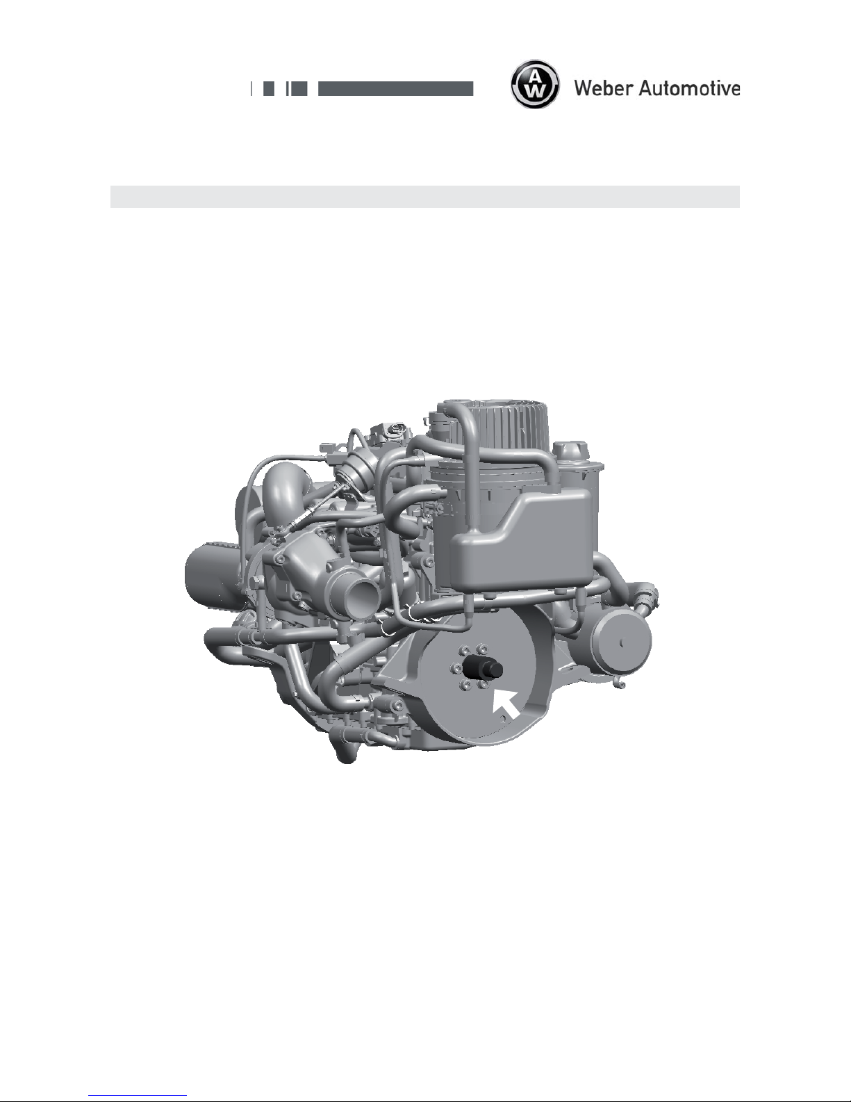
MPE 750 Turbo Marine
Closed Loop
Installation Guide
Page 8
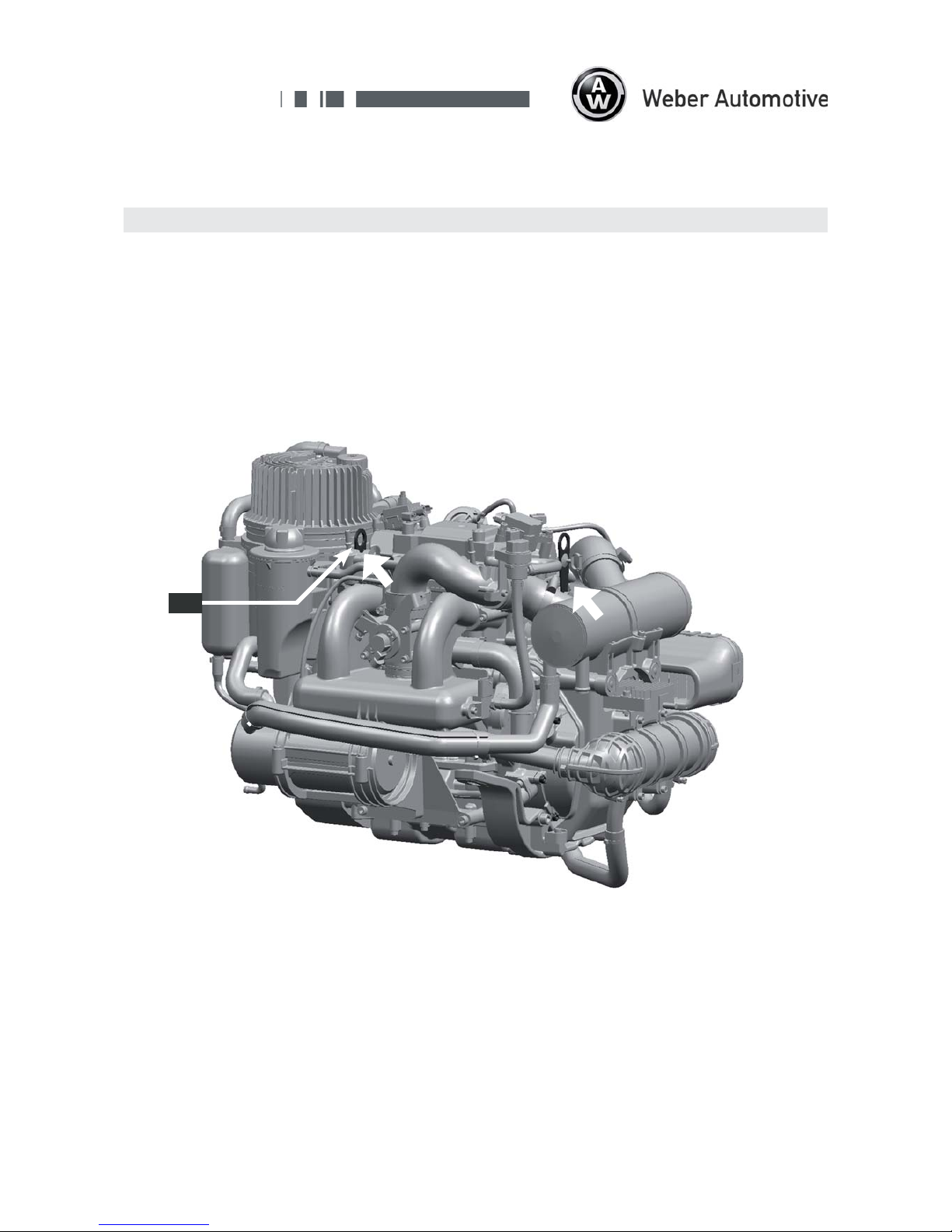
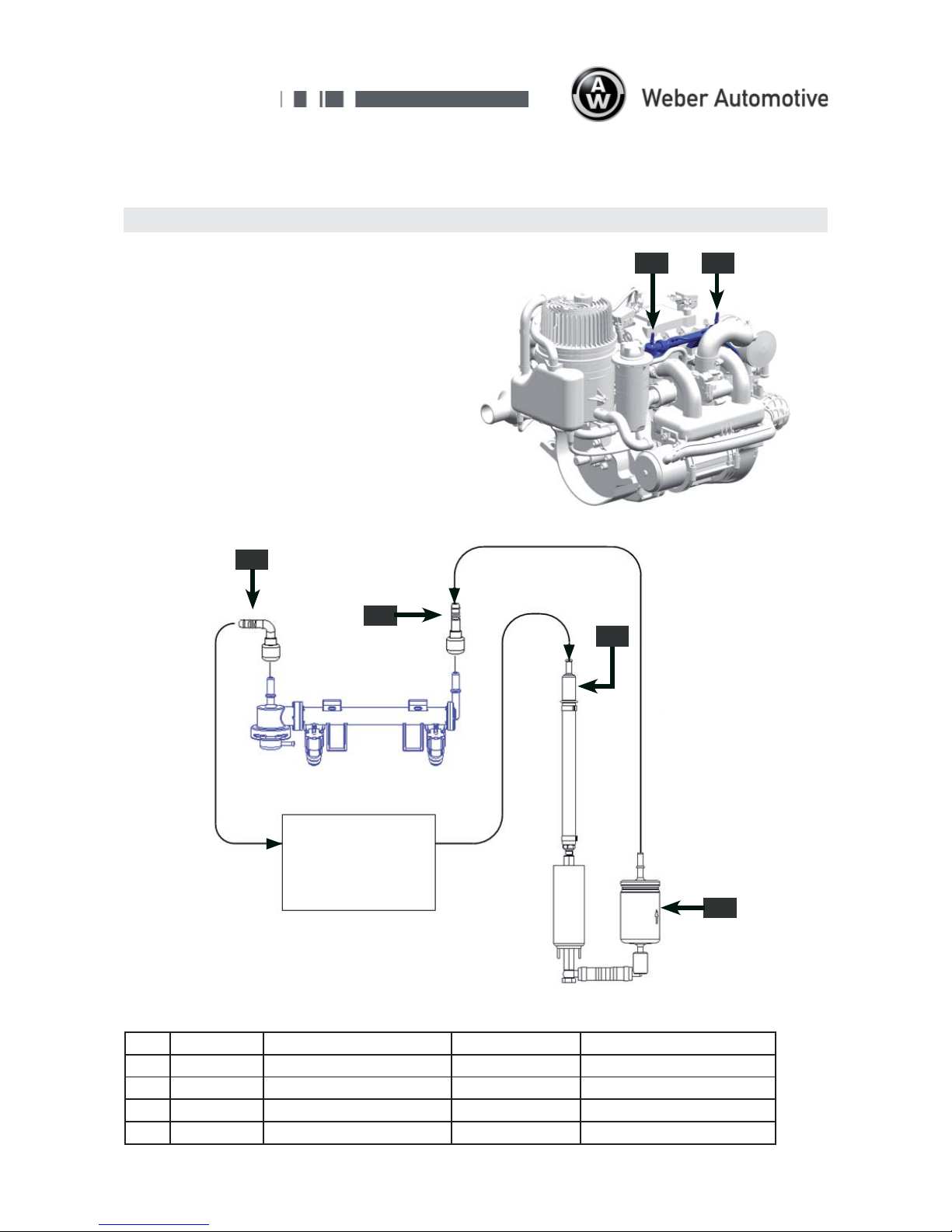
The fuel rails fittings ars designed conform to
SAE J2044. The use of quick connectors (1) (2) is
strictly recommended.
(a) Fuel Feed Line from Fuel Pump: Fitting SAE
J2044 diameter 7,89 mm for quick connector
(b) Fuel Return Line to tank: Fitting SAE J2044
diameter 7,89 mm for quick connectors
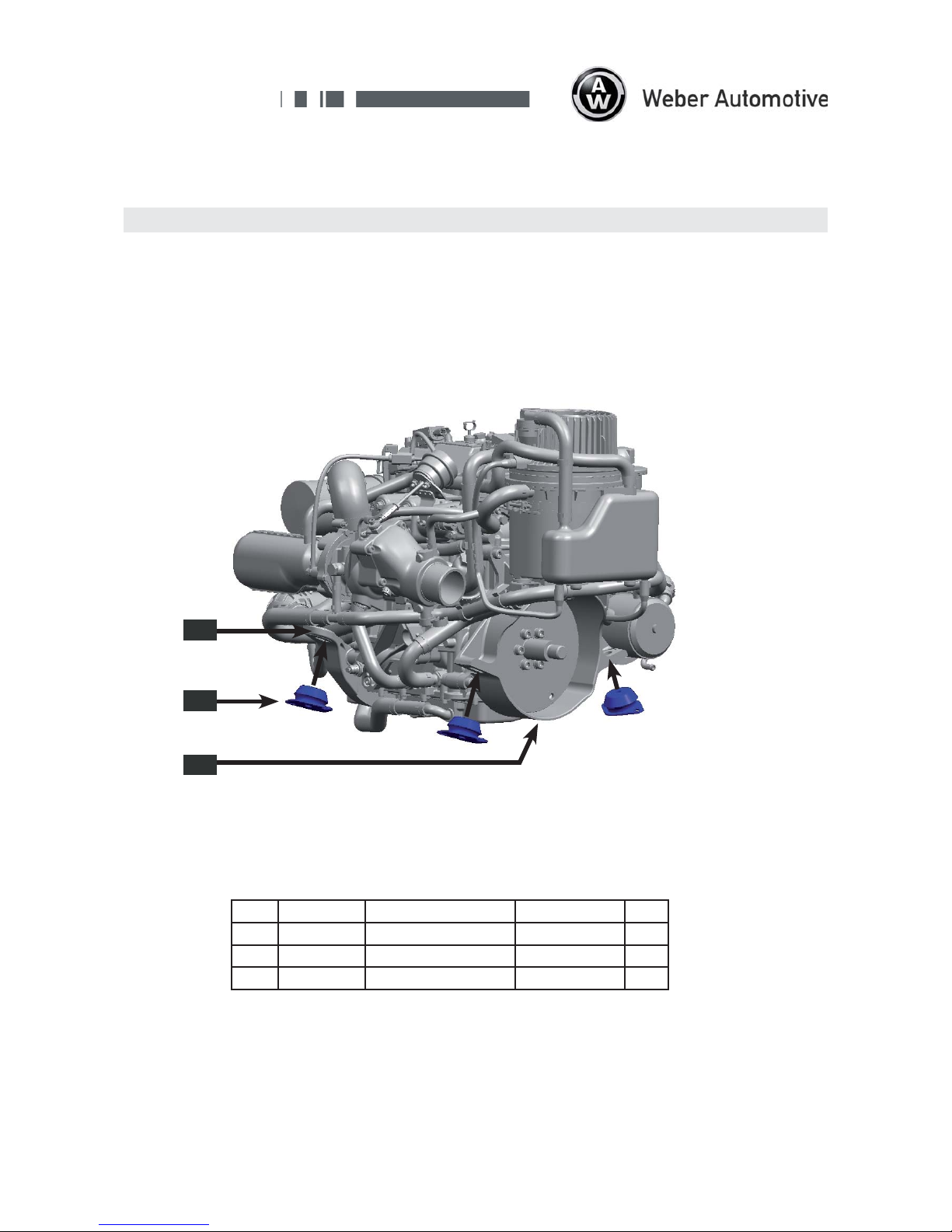
3 Fuel System
Pos. Order No Description Specification Manufacturer
1 104227 quick connector 7,89x90° Weber
2 104228 quick connector 7,89x180° Weber
3 103450 fuel filter, pressure side Mann & Hummel WK512
4 103397 fuel filter, intake side Pierburg 4.000.30.80.0
ba
2
1
fuel tank
4
fuel pump
120liter/hour at 4.5bar
3
fuelrail