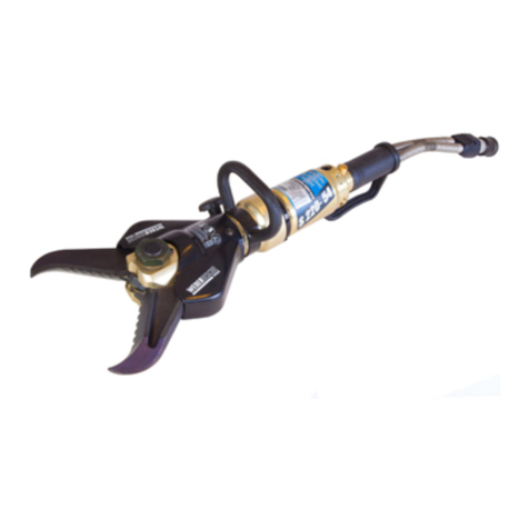
Weber Rescue Systems S 50 User manual

E
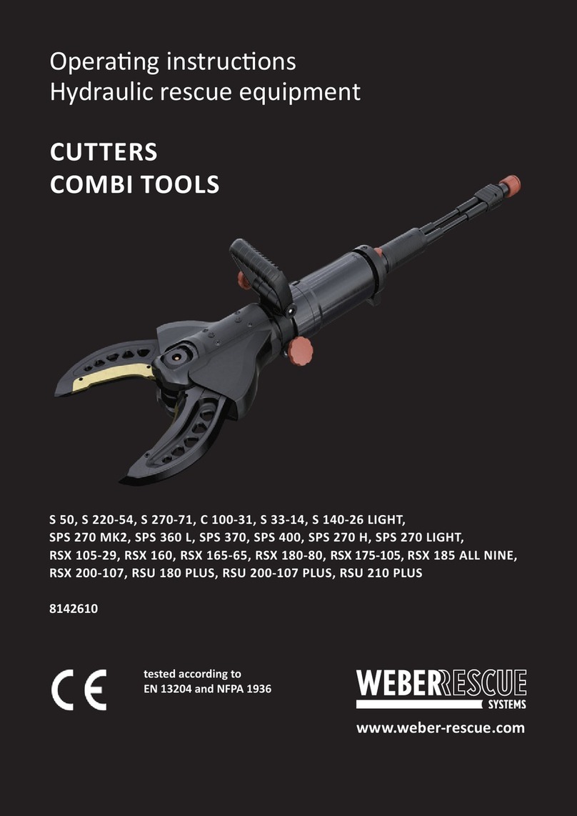
S 50, S 220-54, S 270, C 100-31, S 33-14, S 140-26 LIGHT,
SPS 270 MK2, SPS 360 MK2, SPS 370 MK2, SPS 400 MK2, SPS480 MK2, SPS 270 H,
HANDVARIO RIT, RSX 105, RSX 160, RSX 165-65, RSX 180-80, RSX 175, RSX 185 ALL NINE,
RSX 200-107, RSU 180 PLUS, RSU 210 PLUS,
RSC 170, RSC 170 PLUS, RSC 190, RSC 190 PLUS, RSC 200, RSC F7
Operang instrucons
Hydraulic rescue equipment
CUTTERS
COMBI TOOLS
8142610
www.weber-rescue.com

Content
1. General 4
1.1 Informaon on the operang instrucons 4
1.2 Explanaon of symbols 5
1.3 Limitaon of liability 6
1.4 Copyright 6
1.5 Warranty provisions 7
1.6 Customer Service 7
2. Safety 8
2.1 Intended use 8
2.2 Operator responsibility 10
2.3 Operang personnel 11
2.4 Personal protecve equipment 12
2.5 Parcular hazards 13
2.6 Safety devices 15
2.7 How to respond in the event of danger or accidents 16
2.8 Signage 17
3 Technical data 18
3.1 Cuers 18
3.2 Combi tools 22
3.3 Operang condions 25
3.4 Type plate 25
4 Structure and funcon 26
4.1 Overview 26
4.2 Brief descripon 26
4.3 Hydraulic supply 27
4.4 Equipment connecons 29
4.5 Use of the control handle 31
4.6 Replacing the spreader ps 32
4.7 Replacing blade inserts (PLUS) 33

CONTENT | 3
5. Possible applicaons 35
5.1 Safety informaon 35
5.2 Cung 35
5.3 Spreading (combi tools) 37
5.4 Pulling (combi tools) 37
5.5 Crushing (combi tools) 39
5.6 Liing (combi tools) 39
5.7 Connuous Cuts (C 100-31) 40
5.8 Liing (combi tools) 40
6. Transport, packaging and storage 41
6.1 Safety instrucons 41
6.2 Transport inspecon 41
6.3 Symbols on the packaging 42
6.4 Disposal of packaging 42
6.5 Storage 42
7. Installaon and commissioning 43
7.1 Safety informaon 43
7.2 Checking 44
7.3 Installaon 44
7.4 Shung down (end of work) 45
8. Maintenance 46
8.1 Safety instrucons 46
8.2 Upkeep and maintenance 46
8.3 Maintenance aer operaon in humidity 47
8.4 Maintenance schedule 47
9. Malfuncons 48
10. Decommissioning / Recycling 49
11. EC Declaraon of Conformity 50
12. Notes 51

1. General
1.1 Informaon on the operang instrucons
These operang instrucons provide important informaon on using SMART-FORCE appliances.
To assure safety at the workplace, always observe all safety and handling instrucons contained
in this document.
Furthermore, the local accident prevenon regulaons and general safety determinaons
applicable to the operaon site of the equipment must also be observed.
Before starng any work you must read these operang instrucons thoroughly! They are
a component of the product and must be stored in a known locaon that is accessible to
personnel at all mes.
This documentaon contains informaon about the operaon of your appliance, regardless of
which type of appliance it is. For this reason, you will also nd explanaons that do not relate
directly to your appliance.
All informaon, technical specicaons, graphics and illustraons contained in these Operang
Instrucons are based on the most up-to-date data available at the me these instrucons
were created.
In addion to thoroughly reading the operang instrucons, we also recommend that you
undergo training and instrucon in handling (possible uses, operaonal taccs, etc.) the rescue
equipment from one of our qualied trainers.

GENERAL | 5
1.2 Explanaon of symbols
Warnings
In these operang instrucons, warnings are idened by symbols.
The individual warnings are introduced by signal words expressing the degree of danger.
These warnings must be heeded to prevent accidents, injury and property damage.
DANGER!
… points out an immediately dangerous situaon which can cause death or
severe injury if it is not avoided.
WARNING!
…points out a potenally dangerous situaon which can cause death or
severe injury if it is not avoided.
CAUTION!
…points out a potenally dangerous situaon which can cause minor or
slight injury if it is not avoided.
ATTENTION!
…points out a potenally dangerous situaon which can cause property
damage if it is not avoided.

Tips and recommendaons
NOTE!
…emphasises useful ps and informaon for ecient, trouble-free
operaon.
1.3 Limitaon of liability
All informaon and instrucons in these operang instrucons were compiled under
consideraon of the applicable standards and regulaons, the current state of technology and
our long-standing knowledge and experience.
The manufacturer assumes no liability for damages due to:
• Non-observance of the operang instrucons
• Improper use
• Assigning untrained personnel
• Unauthorised modicaons
• Technical changes
• Use of impermissible replacement parts
• Use of non-original accessories
For special designs or due to technical changes, the actual scope of supply for may dier from
the explanaons and representaons described.
1.4 Copyright
All texts, illustraons, drawings and images in these operang instrucons may be used freely
without prior authorisaon.

GENERAL | 7
NOTE!
Addional informaon, images and diagrams are available on our home
page: www.weber-rescue.com.
1.5 Warranty provisions
The warranty provisions are included with the sales documentaon as a separate document.
1.6 Customer Service
Our Customer Service would be happy to provide you with technical informaon.
Germany
Service Center, Güglingen
Phone: +49 7135 71 10112
E-mail: servicecenter@weber-rescue.com
NOTE!
When contacng our Customer Service, please provide the idencaon,
type and year of manufacture of the appliance. This informaon can be
found on the type plate.
For further processing, please complete
the RMA document in full:
Austria
Service Center, Losenstein
Phone: +43 7255 6237-12473
E-mail: ATL.Servicecenter@weber-rescue.com
Internaonal
For quesons regarding spare parts, service and repair, please contact
our cered local service partners. Scan the following QR code for an
overview of our worldwide service and sales network.

2. Safety
This secon of the operang instrucons presents a comprehensive overview of all important
safety aspects for opmal protecon of the operang personnel as well as for safe, trouble-free
operaon.
Non-observance of the handling and safety instrucons presented in these Operang
Instrucons can result in serious dangers.
2.1 Intended use
The hydraulic baery tools are designed and tested exclusively for the intended applicaons
described here. All other acvies are fundamentally prohibited.
All baery tools are designed as one-man appliances and are therefore to be operated by only
one person.
Cuers S 50, S 220-54, S 270, C 100-31, S 33-14, S 140-26 LIGHT, RSX 105, RSX 160, RSX 165-65,
RSX 180-80, RSX 175, RSX 185 ALL NINE, RSX 200-107, RSU 180 PLUS, RSU 210 PLUS,
RSC 170, RSC 170 PLUS, RSC 190, RSC 190 PLUS, RSC 200, RSC F7
• The baery-powered cung appliances are used exclusively for cung doors and
roof beams, pillars and door sills, the ring and the spokes of the steering wheel.
• If possible, for cung solid material, always use the rear part of the cuer unit as it
is equipped with special edges for cung round material.
• In industrial applicaon, the appliances can also be used to cut pipes, structural
steels, proles, sheets and cables.

SAFETY | 9
Combi tools
SPS 270 MK2, SPS 360 MK2, SPS 370 MK2, SPS 400 MK2, SPS 480 MK2, SPS 270 H,
HANDVARIO RIT
• All combi tools are designed as one-man devices and therefore may be
operated by one person only.
• The devices serve exclusively for the cung of doors and roof pillars,
posts and sills, the rims and spokes of steering wheels.
• The rear cuer secon should be used whenever possible for separang
solid material as this is equipped with special round material cuers.
• In industrial applicaons the equipment can also be used for cung pipes,
construcon steel, proles, sheets and cables.
• In addion, the combi tools can be used for opening doors, liing vehicles,
pushing away vehicle parts and squeezing tubes.
• The chain set is to be used exclusively for pulling.
Accessories - chain sets
• Combi tools may only be used with the appropriate chain set and pulling device.
Pulling chains are exclusively for pulling away obstacles and loads and for enlarging
openings to free trapped persons.
WARNING!
Danger caused by improper use!
Any use other than intended use and/or other type of use of these
appliances can cause dangerous situaons!
Therefore, it is absolutely necessary to:
» Only use the appliances for the intended uses described above.
» Observe all other informaon regarding proper use of the appliances in
Chapter 5 (Possible uses).

2.2 Operator responsibility
In addion to the occupaonal safety informaon in these operang instrucons, the safety,
accident prevenon and environmental prevenon regulaons applicable to the operaon site
of the appliance must also be observed. Thereby, the following applies in parcular:
• The operator must inform himself regarding the applicable occupaonal safety
regulaons and carry out a risk assessment to idenfy addional dangers arising
from the special work condions at the operaon site of the appliance.
• The operator must clearly regulate and determine responsibility for installaon,
maintenance and cleaning.
• The operator must ensure that all persons engaged with the appliance have
completely read and understood the operang instrucons.
• Furthermore, he must train the personnel at regular intervals and inform them of
the dangers associated with handling the appliance.
The operator is also responsible for ensuring that the equipment is always in a technically
awless condion. Therefore, the following applies:
• Aer each me the equipment is used, or at least once a year, a visual inspecon of
the appliance by an instructed person is required (per DGUV guideline 305-002 or
country-specic rules).
• Every three years, or whenever a doubt is raised about the safety or reliability of the
appliance, a funcon and load test must also be carried out (per DGUV guideline
305-002 or country-specic regulaons).
NOTE!
Maintenance work can be carried out by instructed persons. Maintenance
measures and repairs may only be carried out by the appliance manufacturer,
or by specialist personnel trained by the appliance manufacturer and the
authorised service partners. Connuous training and instrucon by the
appliance manufacturer is mandatory for a valid training cercate.

SAFETY | 11
2.3 Operang personnel
The following qualicaons for dierent areas of acvity are specied in the operang
instrucons:
• Instructed persons
Have been instructed by the operator regarding the tasks they have been assigned
and the possible dangers caused by improper acons.
• Expert personnel
Because of their professional training, knowledge and experience as well as their
knowledge of the applicable manufacturer’s provisions, expert personnel are
able to carry out the tasks they have been assigned and independently recognize
potenal dangers.
WARNING!
Danger of injury caused by insucient qualicaons!
Improper handling of these appliances can cause serious injury and
property damage.
Therefore, it is absolutely necessary to:
» Only permit the people specied in the respecve chapters of these
operang instrucons to carry out the special acvity.
»In case of doubt, immediately call in expert personnel.
NOTE!
Never operate the appliance aer consuming alcohol, medicaons or drugs!
NOTE!
Maintenance work can be carried out by instructed persons. Maintenance
measures and repairs may only be carried out by the appliance manufacturer,
or by specialist personnel trained by the appliance manufacturer and the
authorised service partners. Connuous training and instrucon by the
appliance manufacturer is mandatory for a valid training cercate.

2.4 Personal protecve equipment
To minimise danger for the operang personnel, wearing personal protecve equipment (PPE)
when handling the hydraulic rescue equipment is absolutely mandatory.
As a maer of principle, always wear the following protecve clothing for all work:
Safety work clothing
Only wear closely ng work clothing with narrow sleeves and without
projecng pieces while working. This is primarily for protecon against
entanglement in moving parts of the equipment.
Safety shoes
Always wear steel-capped safety shoes to protect
against heavy falling objects and slipping on slippery
surfaces.
Work gloves
Wear safety work gloves to protect against sharp edges and glass splinters
when operang the equipment.
Helmet with face shield
Wear a helmet with face shield to protect against ying or falling parts and
glass splinters.
Protecve goggles
In addion to a face mask, protecve goggles should be worn to protect the
eyes from projecle parcles.
Also wear during any special kinds of work that cause noise:
Ear defenders
To protect your hearing, ear defenders should be worn in addion to
personal protecve equipment.

2.5 Parcular hazards
The dangers resulng from the risk assessment are presented in the following secon.
To minimize potenal health hazards and prevent dangerous situaons, the safety instrucons
listed below and the warning instrucons in the following chapters of these Operang
Instrucons must be observed.
Electrical current
DANGER!
Danger of death due to electrical current!
There is an immediate danger of death if live parts are touched. Damage to
insulaon or individual components can be life-threatening.
Therefore:
» If the insulaon is damaged, immediately disconnect the power supply
and arrange for repairs.
» Only allow electricians to carry out work on the electrical system.
» When any work is being carried out on the electrical system, it must be
disconnected from the mains supply and checked to ensure that it is not
live.
» Before carrying out maintenance, cleaning or repair work, the power
supply must be switched o and secured to prevent it being switched on
again.
» Do not bypass or shut down any fuses.
Use fuses with the correct amperage when replacing.
»Keep live parts away from moisture.
This can cause a short circuit.
SAFETY | 13

Noise
WARNING!
Noise can damage hearing!
The noise occurring in the work area can cause severe hearing damage.
Therefore:
»You should also wear ear protectors when carrying out
certain noise-producing tasks.
»Do not stay in the hazardous area longer than necessary.
Hydraulic power
WARNING!
Hydraulic power hazard!
Serious injury can result due to the released hydraulic forces and escaping
hydraulic oil.
Therefore:
»Constantly monitor the device during the work procedure and
set down if necessary.
»Inspect the hose lines and devices for damage aer every use.
»Avoid skin contact with the hydraulic oil (wear protecve gloves).
»Immediately remove the hydraulic oil from wounds and consult
a doctor.

TECHNICAL SPECIFICATIONS | 15
2.6 Safety devices
Safety valve for SKS couplings
If the return line is not correctly coupled such that the oil cannot return then a safety valve
integrated into the control handle actuates in order to protect the equipment and the
operator. This causes hydraulic oil to seep harmlessly from the end of the handle.
Move the switching valve on the hydraulic power unit immediately to the „0“ posion and
connect the coupling parts together correctly.

2.7 How to respond in the event of danger or accidents
Preventave measures
• Always be prepared for accidents
• Keep rst aid equipment (rst-aid box, blankets etc.) at hand
• Familiarise personnel with accident alarms, rst-aid gear and
emergency equipment
• Keep entryways clear for emergency vehicles
In the event of an accident
• Shut down equipment immediately
• Iniate rst aid measures
• Get people out of the danger zone
• Inform the responsible pares at the site of the incident
• Nofy a doctor and/or the re brigade
• Clear entryways for emergency vehicles

2.8 Signage
The equipment bears the following symbols and instruconal signs.
They refer to the immediate vicinity in which they are axed.
Comply with the operang manual
Do not use the marked equipment unl you have read the operang
manual.
Hand injury warning
When working with the equipment, take care to avoid hand injuries through
trapping or sharp edges.
WARNING!
Danger of injury due to illegible symbols!
Over me, sckers and symbols on the equipment can become soiled or
otherwise illegible.
Therefore, make absolutely sure to:
»Keep all safety, warning and operang informaon on the
device easily legible.
»Replace damaged signs and sckers immediately.
TECHNICAL SPECIFICATIONS | 17

575 mm 642 mm 718 mm 711 mm 819 mm 866 mm
183 mm 172 mm 236 mm 225 mm 298 mm 298 mm
157 mm 143 mm 158 mm 202 mm 225 mm 225 mm
9,2 kg 7,9 kg 14,5 kg 16,3 kg 21,9 kg 22,4 kg
100 mm 140 mm 160 mm 165 mm 170 mm 265 mm
700 bar 700 bar 700 bar 700 bar 700 bar 700 bar
AC100D-9,2
1E-2E-3E-4D-5G
AC115D-7,9
1F-2D-3D-4D-5G
BC160H-14,5
1I-2K-3H-4J-5H
BC165F-16,3
1J-2F-3G-4J-5G
BC178K-21,9
1K-K-3K-4K-5K
CC240K-22,4
1K-2K-3K-4K-5K
A5-B4-C5-
D6-E6-F2 A5-B3-C4-D6-E7 A7-B8-C6-D7-E8 A8-B6-C6-
D7-E9-F3
A8-B9-C8-
D9-E9-F5
A9-B9-C9-
D9-E9-F5
1096350 1075652 1093226 5932068 1096171 1093248
3 Technical data
3.1 Cutters
RSX 105 S 140-26 LIGHT RSX 160 RSX 165-65 RSX 175 RSX 185 ALL NINE
Length
Width
Hight
Weight
Opening width
Nominal pressure
EN class
NFPA class
ID No.
RSX 175-105 RSX 185 ALL NINE
RSX 160 RSX 165-65
S 140-26 LIGHT
RSX 105

740 mm 737 mm 833 mm 833 mm
232 mm 236 mm 265 mm 260 mm
206 mm 159 mm 217 mm 221 mm
17,6 kg 16,7 kg 19,7 kg 19,6 kg
180 mm 185 mm 200 mm 210 mm
700 bar 700 bar 700 bar 700 bar
BC180I-17,6
1J-2K-3I-4J-5J
BC185J-16,7
1J-2K-3K-4K-5K
CC200J-19,7
1J-2K-3K-4K-5K
CC200K-19,6
1K-2K-3K-4K-5K
A7-B9-C7-D9-E9 A8-B9-C7-D9-E9-F4 A8-B9-C8-D9-E9 A8-B9-C8-D9-E9-F4
1059226 1093279 5935849 1093298
RSX 180-80 RSU 180 PLUS RSX 200-107 RSU 210 PLUS
Length
Width
Hight
Weight
Opening width
Nominal pressure
EN class
NFPA class
ID No.
TECHNICAL SPECIFICATIONS | 19
RSU 180 PLUS
RSX 200-107 RSU 210 PLUS
RSX 180-80

585 mm 362 mm 388 mm 728 mm 765 mm
205mm 138 mm 71 mm 236 mm 236 mm
243 mm 71 mm 129 mm 196 mm 161 mm
19,5 kg 4,2 kg 3,9 kg 14,4 kg 16,7 kg
120 mm 50 mm 30 mm 220 mm 280 mm
700 bar 700 bar 700 bar 700 bar 700 bar
AC120D-19,5
1J-2K-3I-4J-5J
AC50B-4,2
1C-2D-3B
-
-
BC170H-14,4
1I-2H-3H-4K-5I
CC218I-16,7
1I-2K-3I-4K-5J
A4-B3-C5-D6-E6-
D6-E6 A4-B3-C2-D4-E3 A3-B2-C1-D2-E2 A7-B7-C6-D8-E8 A7-B8-C7-D8-E9-F6
5935199 1093906 2836661 1063372 1096170
C 100-31 S 50 S 33-14 S 220-54 S 270
Length
Width
Hight
Weight
Opening width
Nominal pressure
EN class
NFPA class
ID No.
RSC 170 RSC 170 PLUS RSC 190 RSC 190 PLUS RSC 200 RSC F7
Length
Width
Hight
Weight
Opening width
Nominal pressure
EN class
NFPA class
ID No.
S 270
S 50 S 33-14
C 100-31
S 220-54
RSC 170
Other manuals for S 50
1
This manual suits for next models
55
Table of contents
Other Weber Rescue Systems Cutter manuals

Weber Rescue Systems
Weber Rescue Systems S 50-14 User manual

Weber Rescue Systems
Weber Rescue Systems S 270-71 User manual

Weber Rescue Systems
Weber Rescue Systems SPS 270 MK2 E-FORCE3 User manual

Weber Rescue Systems
Weber Rescue Systems SPS 270 MK2 E-FORCE 2 User manual

Weber Rescue Systems
Weber Rescue Systems S 50 User manual