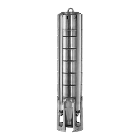
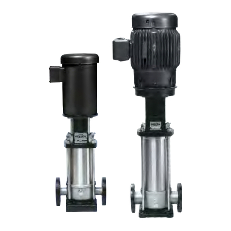
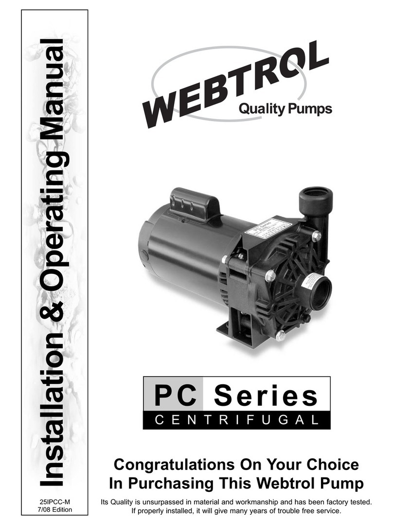
webtrol WTE Series Installation instructions

Installation & Operating Manual
Congratulations on Your Choice in Purchasing this ebtrol Pump!
Its Quality is unsurpassed in material and workmanship and has been factory tested.
If properly installed, it will give many years of trouble free service.
WTE Series
10/19 Edition
Stainless Steel Fitted Turbine Effluent Pump

Subject Page
Pre-Installation 2
Installation 3
Typical Tank Installation 4-6
Wiring Diagrams 6
System Trouble Shooting 7-8
Examine the components carefully to ensure that no damage has occurred to the liquid end, motor, or cable during ship-
ment. Report damage immediately to the shipping carrier or to your dealer / distributor. The Webtrol Effluent
Submersible Pump should remain in the shipping carton until it is ready to be installed. Do not drop or mishandle the
pump prior to installation.
arning: The motor is equipped with an electrical cable. It should NEVER be used to lift or carry the pump.
Damage to the electrical cable can cause shock, burns or death!
Only qualified personnel should install the pump and associated control equipment.
For your protection, make certain the pump ground wire is properly connected to the ground wire with the incoming
power supply.
All wiring must meet National Electrical Code or Canadian Electrical Code and local code requirements.
To properly size fuses / circuit breakers / wire size See Table 1.
Electrical supply MUST match the pumps nameplate specifications. Incorrect voltage can cause fire, damage to the
motor and voids the warranty.
“Do Not” install the pump in a hazardous location.
Pump performance is based upon pumping clear (68 deg. F) water that is free of air or gases.
Typical installations are shown in Figures 2-4, Pages 4-6.
- 2 -
Table Of Contents
Pre-Installation
1/2 244504 115 12 35 20 30 100 160 250 390 620 960 1460
1/2 244505 230 6 20 10 15 400 650 1020 1610 2510 3880 5880
3/4 244507 230 8 25 15 20 300 480 760 1200 1870 2890 4370
1 244508 230 9.8 30 20 25 250 400 630 990 1540 2380 3610
1 1/2 244309 230 13.1 35 20 30 190 310 480 770 1200 1870 2850
Table 1 - ebtrol’s Two ire, Single Phase, Submersible Motors
Motor
Model
Pre ix
Circuit Breakers Or Fuse Amps
(Maximum Per NEC) Cable Selection Chart Copper Size AWG
Maximum Distance From Service Entrance
To motor, Feet
HP Volts S.F.
Amps Standard
Fuse
Circuit
Breaker
Dual Element
Time Delay
Fuse 14 12 10 8 6 4 2

Pump should be sized correctly for flow, head, and include friction losses.
If the discharge pipe is subject to freezing, protect the system from freeze up. The discharge pipe can be insulated. If a
check valve is not installed, the “on-off” cycle must be adjusted for any back-flow from the discharge pipe.
Note! The thermoplastic and stainless steel pumps are shipped without a check valve.
The pump can operate in water up to 86F. In the event, the water temperature exceeds 86F, the motor horsepower must
be de-rated.
Installation
- 3 -
Figure 1 - Vent Hole Location
The pump can be installed vertically / horizontally by placing it on a support located on the bottom of the tank, or sup-
ported by a device to hang the pump from the top of the tank.
Pipe joint compound can cause thermoplastic to crack. Use only teflon tape when sealing joints in the plastic pipe of
connecting pipe to the thermoplastic discharge used on the Thermoplastic Effluent Submersible Pumps.
When a check valve is used a 1/16” diameter hole must be drilled in the nipple above the discharge and below the
check valve. See Figure 1 below for ent hole location.
On models with a built in check valve, drill a 1/16” diameter hole in pipe if drain back is required.
For typical tank installations, See Figures 2-4

- 4 -
Typical Tank Installations
Figure 2 - Typical Installation

Typical Tank Installations
- 5 -
Figure 3 - Typical Installation

- 6 -
Single Phase Motors - iring Diagram
Figure 4 - Typical Installation
Typical Tank Installations - Continued

- 7 -
Motor Runs Continuously
Cause of Trouble Checking Procedure Correction Action
Motor Runs But Overload Trips Or Blows Fuse
Cause of Trouble Checking Procedure Correction Action
System Trouble Shooting
Motor Does Not Start
Cause of Trouble Checking Procedure Correction Action
A. No power or incorrect voltage. Using voltmeter check the line terminals. Voltage must Contact power company if voltage is incorrect.
be + 10% of rated voltage.
B. Fuses blown or circuit breakers tripped. Check fuses for recommended size and check for Replace with proper fuse or reset circuit breaker.
loose, dirty, or corroded connections in fuse receptacle.
Check for tripped circuit breaker.
C. Float assembly held down. Inspect float assembly. Replace / repair float assembly.
D. Defective cable or motor. Contact factory for copy of Franklin Electric Application, Repair or replace.
Installation & Maintenance Manual.
E. Defective wiring. Check for loose or corroded connections. Check motor Correct faulty wiring or connections.
lead terminals with voltmeter for power.
F. Bound pump. ocked rotor conditions can result from misalignment If pump will not start with several trials, it must be
between pump and motor or bound pump. pulled and the cause corrected.
Amp readings 3 to 6 times higher than normal will be
indicated.
A. Defective level switch(s). Check switch and examine for defects. Replace switch or adjust level of switch.
B. Check valve, stuck open. Damaged or defective check valve will not hold Replace if defective.
pressure or prevent backflow.
C. Pump Tank to small. Recalculate tank size. Increase tank size.
D. eak in effluent system. Check system for leaks. Replace damaged pipes or repair leaks.
A. Defective switch. Switch does not open. Replace.
B. eak in effluent system. Check system for leaks in tank or lines. Replace damaged pipes or repair leaks.
C. Debris under float assembly, bound by pit sides. Inspect float assembly. Remove debris, replace / repair float assembly.
D. oose or broken motor shaft. No or little water will be delivered if coupling between Check for damaged shafts if coupling is loose and
motor and pump shaft is loose or if a jammed pump replace worn or defective units.
has caused the motor shaft to shear off.
E. Pump screen blocked. Restricted flow may indicate a clogged intake screen Clean primary and secondary screen.
on pump.
F. Check valve stuck closed. No water will be delivered if check valve is in closed Replace if defective.
position.
A. Incorrect voltage. Using voltmeter, check the line terminals. Voltage must Contact power company if voltage is incorrect.
be within + 10% of rated voltage.
B. Defective motor or cable. Contact factory for copy of Franklin Electric Application, Repair or replace.
Installation & Maintenance Manual.
C. Worn pump or motor.
Motor Starts Too Often
Cause of Trouble Checking Procedure Correction Action

- 8 -
Owners Information
Name Of Dealer: Phone:
Address:
Installed By: Date:
Pump Model No: HP: Date Code:
Power Supply: Volts: Service Factor Amps:
Cable Size: AWG: Ft.:
Riser Pipe Size: Material: ength (Inches):
Septic Tank Size Gallons:
Float Height (Inches): Pump On, Off, Timer Override (Inches): On, Off
ow evel Cutoff (Inches): Redundant Off (Inches):
Timer Settings (Minutes/Hours): On Off High evel Alarm (Inches):
Note! Float location to be measured from the bottom of the tank.
Other Information:
Little Or No Liquid Delivered By Pump
Cause of Trouble Checking Procedure Correction Action
A. Faulty or incorrectly installed check valve. Inspect check valve. Is it installed backwards? Replace if defective / clean vent hole.
If check valve is used, vent hole must be clear.
B. Worn Pump after a period of use. With the pump running, close the discharge valve & Pull pump & replace rotating assembly.
record pressure. If low, pump may be worn due to
abrasive materials / adverse chemicals.
C.Pump bound by abrasive material. Amp readings 3 to 6 times higher than normal will be Pull pump & clean.
indicated.
D. Pump screens blocked. Inspect primary/secondary screens. Clean screens.
D. ow Voltage. Measure incoming voltage. If low, contact local electric company.
E. Water contains air or gases. Water level should not be below suction inlet of pump. Adjust cut-off level of switch. Adjust cut-off level
of float for on-off switch.
Thank You for Purchasing an Effluent Series Pump
We at Webtrol are constantly working on new products to make your job easier, while making your systems more efficient, reliable
and affordable. Your opinion means a lot to us, so please let us know what you think about our WTE Series Effluent Pump.
8417 New Hampshire Ave. | St. ouis, MO 63123
Other webtrol Water Pump manuals

webtrol
webtrol TC Series User manual

webtrol
webtrol PC Series Installation instructions

webtrol
webtrol WT Series Installation instructions

webtrol
webtrol IN-LINE Series Installation instructions

webtrol
webtrol EZ Series Operating instructions

webtrol
webtrol EZ Series Operating instructions

webtrol
webtrol NV Series Installation instructions

webtrol
webtrol VN50C49 Installation instructions
Popular Water Pump manuals by other brands

QEP
QEP 75021 user manual

DAB
DAB DAB E.SYBOX Instruction for installation and maintenance

Becker
Becker SV 5.300 operating instructions

North Ridge Pumps
North Ridge Pumps Hose pump Series manual

Mixtron
Mixtron MXO1.075.P110.00 Operating and maintenance manual

Cosmo
Cosmo Cosmo CPZ Installation and operating instructions