Weco Discovery 221AC/DC-VRD Evo User manual

Cod. 006.0001.2000
08/03/2022 V.2.2
Discovery 221AC/DC Evo
221AC/DC-VRD Evo
Discovery 300AC/DC Evo
300AC/DC-VRD Evo
Instruction manual
ENG
Translation of original instructions

Cod. 006.0001.2000
08/03/2022 V.2.2 Discovery 221AC/DC Evo/VRD Evo
Discovery 300AC/DC Evo/VRD Evo
2
ENGLISH

Cod. 006.0001.2000
08/03/2022 V.2.2
Discovery 221AC/DC Evo/VRD Evo
Discovery 300AC/DC Evo/VRD Evo
3
ENGLISH
INDEX
1 INTRODUCTION.......................................................................................................................................... 4
1.1 INTRODUCTION.......................................................................................................................................... 5
2 INSTALLATION .......................................................................................................................................... 6
2.1 CONNECTIONS TO THE ELECTRICAL MAINS NETWORK...................................................................... 6
2.2 FRONT PANEL............................................................................................................................................. 6
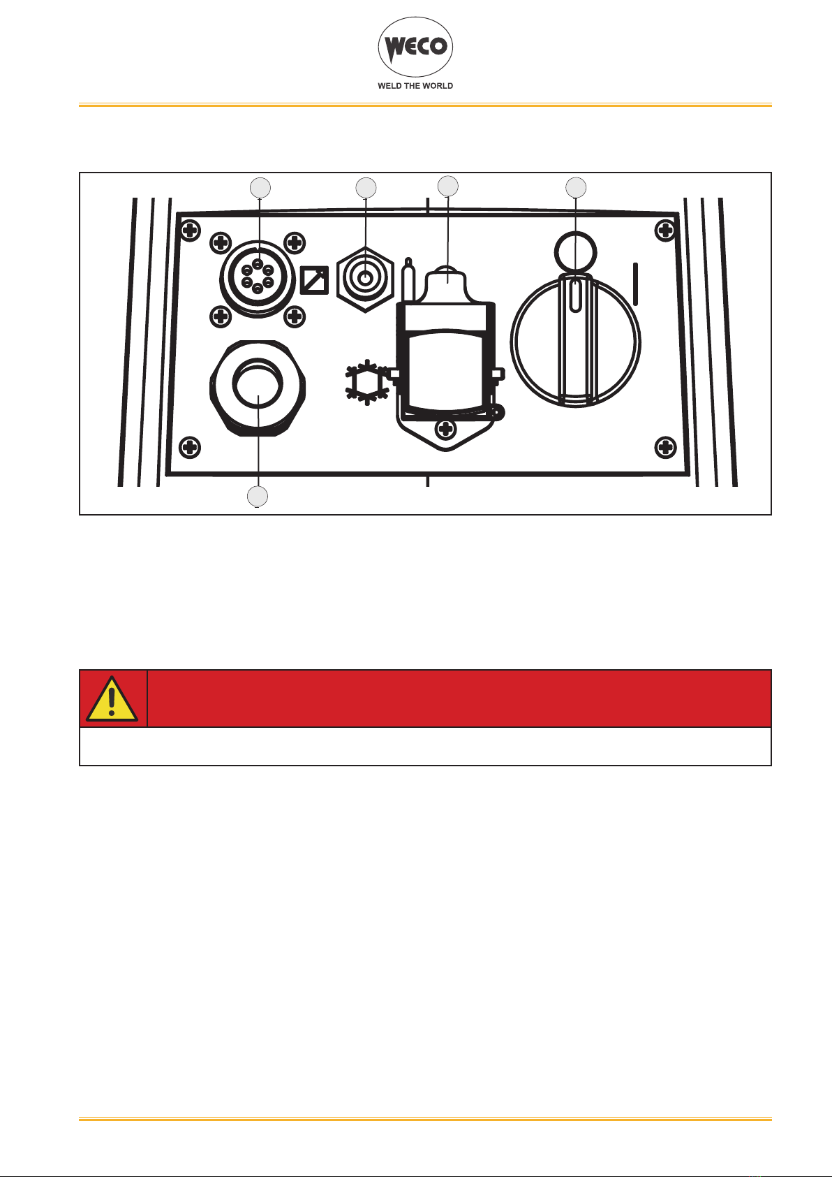
2.3 REAR PANEL............................................................................................................................................... 7
2.4 PREPARING FOR MMA WELDING............................................................................................................. 8
2.5 PREPARING FOR TIG WELDING............................................................................................................... 9
3 USER INTERFACE .................................................................................................................................... 10
4 UNIT POWER-UP ...................................................................................................................................... 12
5 RESET (LOAD FACTORY SETTINGS)..................................................................................................... 12
6 SET UP (INITIAL SET-UP OF THE WELDING POWER SOURCE) ......................................................... 14
7 ALARM MANAGEMENT ........................................................................................................................... 18
8 MMA WELDING ........................................................................................................................................ 20
8.1 MMA WELDING - FIRST LEVEL MENU .................................................................................................... 20
8.2 MMA WELDING -SECOND LEVEL MENU ................................................................................................ 22
8.3 MMA WELDING - SPECIAL FUNCTIONS ................................................................................................. 24
9 TIG WELDING ........................................................................................................................................... 25
9.1 TIG WELDING - FIRST LEVEL MENU ...................................................................................................... 25
9.2 TIG WELDING - SECOND LEVEL MENU ................................................................................................. 30
9.3 TIG DC WELDING - SPECIAL FUNCTIONS MENU ................................................................................. 34
9.4 TIG AC WELDING - SPECIAL FUNCTIONS MENU.................................................................................. 39
10 TORCH TRIGGER PROCEDURE ............................................................................................................. 44
10.1 2 STROKE SPOT - Q-SPOT FUNCTION .................................................................................................. 51
11 JOBS MANAGEMENT .............................................................................................................................. 57
11.1 SAVING A JOB...........................................................................................................................................57
11.2 DELETING A JOB ...................................................................................................................................... 58
11.3 LOADING A JOB ........................................................................................................................................ 59
11.4 EXPORTING/IMPORTING JOBs (through a USB memory stick).............................................................. 60
11.5 SELECTING JOBS USING THE TORCH BUTTONS ................................................................................ 62
12 TECHNICAL DATA .................................................................................................................................... 63
12.1 DISCOVERY 221AC/DC EVO ................................................................................................................... 64
12.2 DISCOVERY 300AC/DC EVO ................................................................................................................... 65
13 ELECTRICAL DIAGRAM .......................................................................................................................... 66
13.1 DISCOVERY 221AC/DC EVO ................................................................................................................... 66
13.2 DISCOVERY 300AC/DC EVO ................................................................................................................... 67
13.3 TORCH CONNECTOR (front panel) .......................................................................................................... 68
13.4 REMOTE CONTROL CONNECTOR (back panel).....................................................................................68
14 SPARE PARTS .......................................................................................................................................... 69
14.1 DISCOVERY 221AC/DC EVO ................................................................................................................... 69
14.2 DISCOVERY 300AC/DC EVO ................................................................................................................... 71

Cod. 006.0001.2000
08/03/2022 V.2.2 Discovery 221AC/DC Evo/VRD Evo
Discovery 300AC/DC Evo/VRD Evo
4
ENGLISH
1 INTRODUCTION
IMPORTANT!
This handbook must be consigned to the user prior to installation and commissioning of the unit.
Read the "General prescriptions for use" handbook supplied separately from this handbook before
installing and commissioning the unit.
The meaning of the symbols in this manual and the associated precautionary information are given in
the "General prescriptions for use”.
If the "General prescriptions for use" are not present, it is mandatory to request a replacement copy
from the manufacturer or from your dealer.
Retain these documents for future consultation.
LEGEND
DANGER!
This pictogram warns of danger of death or serious injury.
WARNING!
This pictogram warns of a risk of injury or damage to property.
CAUTION!
This pictogram warns of a potentially hazardous situation.
INFORMATION
This pictogram gives important information concerning the execution of the relevant operations.
Thissymbolidentiesanactionthatoccursautomaticallyasaresultofapreviousaction.
Thissymbolidentiesadditionalinformationorareferencetoadifferentsectionofthemanual
containing the associated information.
§ Thissymbolidentiesareferencetoachapterofthemanual.
*1 The symbol refers to the associated numbered note.
NOTES
Theguresinthismanualarepurelyguidelineandtheimagesmaycontaindifferenceswithrespectto
theactualequipmenttowhichtheyrefer.

Cod. 006.0001.2000
08/03/2022 V.2.2
Discovery 221AC/DC Evo/VRD Evo
Discovery 300AC/DC Evo/VRD Evo
5
ENGLISH
1.1 INTRODUCTION
Discovery221AC/DCEvo/VRDEvoisanadvancedtechnologysingle-phaseweldingpowersourcefor
ACandDCTIGweldingoperations.
Discovery300AC/DCEvo/VRDEvoisanadvancedtechnologythree-phaseweldingpowersourcefor
ACandDCTIGweldingoperations.
ACTIGfunctionsareidealforaluminium,magnesiumandrelatedalloyswelding.
Mildsteel,stainlesssteelandcoppercanbeeasilyweldedinDCTIG.
ACTIGweldingisoptimizedthanksto:
Synergic arc strike can be selected by the user interface according to tungsten electrode diameter.
ExtrafusionfunctionmaximizesarcfocusingforconsiderablethinmaterialinACTIGwelding.
Mixed AC/DC increases arc penetration for thick aluminium plates.
PulsedACTIGmodewhichpreventstheriskofdeformationoftheworkpieceinthecaseofprolonged
weldingoperations.
Upto4,00mmdiameterelectrodeweldingispossibleinMMA.
Thefanisturnedononlyduringwelding,attheendoftheweldingprocessitremainsonforaxed
periodoftimeaccordingtoweldingconditions.
Thefanisnonethelesscontrolledbyspecicthermalsensorsthatguaranteeacorrectcoolingofthe
machine.
Accessories/ancillary devices that can be connected to the unit:
- manualremotecontrolforremoteadjustmentoftheweldingcurrent.
- foot-pedalremotecontrolforTIGtorcharcstrikingandremoteadjustmentofweldingcurrent.
- UP/DOWNtorchortorchwithpotentiometer.
- liquid cooler for TIG torches.
Consultyourdealerforanupdatedlistofaccessoriesandthelatestnewproductsavailable.

Cod. 006.0001.2000
08/03/2022 V.2.2 Discovery 221AC/DC Evo/VRD Evo
Discovery 300AC/DC Evo/VRD Evo
6
ENGLISH
2 INSTALLATION
DANGER!
Lifting and positioning
Read the warnings highlighted by the following symbols in the “General prescriptions for use”.
2.1 CONNECTIONS TO THE ELECTRICAL MAINS NETWORK
Themainspowersupplyfeaturestowhichtheequipmentshouldbeconnectedaregiveninchapter“12
TECHNICAL DATA” at page 63.
Themachinecanbeconnectedtomotorgeneratorsprovidedtheirvoltageisstabilised.
Connect/disconnectthevariousdeviceswiththemachineswitchedoff.
2.2 FRONT PANEL
1234
○ Negativepoleweldingsocket.[Item1].
○ Connectorforgasfeedhose:gasowfromthepowersourcetothetorch.[Item2].
○ TIGTORCHcontrolconnector[Item3].
○ Positivepoleweldingsocket.[Item4].

Cod. 006.0001.2000
08/03/2022 V.2.2
Discovery 221AC/DC Evo/VRD Evo
Discovery 300AC/DC Evo/VRD Evo
7
ENGLISH
2.3 REAR PANEL
1 2 4
5
○ Remotecontrolconnector[Item1].
○ Connectorforgasfeedhose:gasowfromthecylindertothepowersource[Item2].
○ Coolingunitpowerfeedingconnector[Item3].
• Voltage:230Va.c.
• Currentoutput:1.35A
• IPprotectionrating:IP20(capopen)/IP66(capclosed)
DANGER!
High voltage!
If the socket is not connected to any devices always close the cap
○ WeldingpowersourceON/OFFswitch[Item4].
○ Powercable.[Item5].
• Length(outerside):2,05m
• Numberandcrosssectionofwires:3x2.5mm2(on221AC/DCEvo/VRDEvo)/4x2.5mm2
(on300AC/DCEvo/VRDEvo)
• Powerplugtype:Schuko250Va.c./16A(on221AC/DCEvo/VRDEvo)/notsupplied(on
300AC/DCEvo/VRDEvo)
3

Cod. 006.0001.2000
08/03/2022 V.2.2 Discovery 221AC/DC Evo/VRD Evo
Discovery 300AC/DC Evo/VRD Evo
8
ENGLISH
2.4 PREPARING FOR MMA WELDING
1. SettheweldingpowersourceON/OFFswitchto“O”(unitswitchedoff).
2. Plugthepowercableplugintoamainssocketoutlet.
3. Choosetheelectrodebasedonthetypeofmaterialandthicknessoftheworkpiecetobewelded.
4. Insert the electrode in the electrode holder.
5. Connecttheelectrodeholdercabletotheweldingsocketbasedonthepolarityrequestedbythe
type of electrode used.
6. Connecttheplugofthegroundclamptotheweldingsocketonthebasisofthepolarityrequired.
7. Connecttheearthclamptotheworkpiecebeingprocessed.
DANGER!
Electric shock hazard!
Read the warnings highlighted by the following symbols in the “General prescriptions for use”.
8. SettheweldingpowersourceON/OFFswitchto“I”(unitpowered).
9. Selectthefollowingweldingmodeontheuserinterface:MMA
10.Settherequiredweldingparametervaluesontheuserinterface.
Whentheremotecontroller[RC]isconnectedandtherelativelockingscrewistightened,welding
current can be adjusted using the remote controller.
Thesystemisreadytostartwelding.
REAR VIEW FRONT VIEW
(polarity to basic electrode)
REMOTE
CONTROL

Cod. 006.0001.2000
08/03/2022 V.2.2
Discovery 221AC/DC Evo/VRD Evo
Discovery 300AC/DC Evo/VRD Evo
9
ENGLISH
2.5 PREPARING FOR TIG WELDING
NOTE: For the cooler to power source assembly procedure refer to the cooler instruction
manual.
1. SettheweldingpowersourceON/OFFswitchto“O”(unitde-energized).
2. Plugthepowercableplugintoamainssocketoutlet.
3. Connectthegashosefromtheweldinggascylindertothereargassocket.
4. Openthecylindergasvalve.
5. Choosetheelectrodebasedonthetypeofmaterialandthicknessoftheworkpiecetobewelded.
6. Insert the electrode in the TIG torch.
7. Connectthetorchplugtotheweldingsocketonthebasisofthepolarityrequiredbythetypeof
electrode in question.
8. Connecttheplugofthegroundclamptotheweldingsocketonthebasisofthepolarityrequired.
9. Connectthegashosefromtheweldingtorchtothefrontgassocket.
10.ConnecttheweldingtorchconnectortotheTIGtorchsignalsconnector.
11.Connecttheearthclamptotheworkpiecebeingprocessed.
12.SettheweldingpowersourceON/OFFswitchto“I”(unitpowered).
13.Selectthefollowingweldingmodeontheuserinterface:DCTIG
14.Pressthetorchtriggerwiththetorchwellclearofanymetalparts.Thisservestoopenthegas
solenoidvalvewithoutstrikingtheweldingarc.
15.Usetheowcontrolvalvetoadjusttheowofgasasrequiredwhilethegasisowingout.
16.Settherequiredweldingparametervaluesontheuserinterface.
Whentheremotecontrolpedalisconnectedandtherelativelockingscrewistightenedtheweld-
ingcurrentwillvaryinrelationtothepressureexertedonthepedal.
Thesystemisreadytostartwelding.
REAR VIEW FRONT VIEW
(polarity for tungsten electrode)
REMOTE
CONTROL

Cod. 006.0001.2000
08/03/2022 V.2.2 Discovery 221AC/DC Evo/VRD Evo
Discovery 300AC/DC Evo/VRD Evo
10
ENGLISH
3 USER INTERFACE
Discovery 221AC/DC Evo/VRD Evo - Discovery 300AC/DC Evo/VRD Evo
MenuMenu
Q-SPOT
ACAC
DYN arc
QST
M-TACK
MIX ac/dcMIX ac/dc
HF
SYN
HzHz
E1/S5
S3
L2
D1
USB S4S2S1
L1
L3
L4
L5
L6
L7
L8
L9
L10
L11
L12
L13
L14
L15
L16
CODE SYMBOL DESCRIPTION
L1
QST
DCTIGmode:illuminationshowsthatthefollowingparametercanbeset:Q-START
MIX ac/dcMIX ac/dc
ACTIGmode:illuminationshowsthatthefollowingparametercanbeset:MIXAC/DC
L2
DYN arc
DCTIGmode:illuminationshowsthatthefollowingparametercanbeset:DYNAMICARC
ACTIGmode:illuminationshowsthatthefollowingparametercanbeset:EXTRAFUSION
L3
M-TACK
DCTIGmode:illuminationshowsthatthefollowingparametercanbeset:MULTITACK
HzHz
ACTIGmode:illuminationshowsthatthefollowingparametercanbeset:ACFREQUENCY
(Hz)
L4
ACTIG mode/ DCTIGmode: illuminationshowsthatthefollowing parametercan beset:
ELECTRODE DIAMETER (mm)
ACTIGmode:ThisLEDasheswhenthesetweldingcurrentistoohighinrelationtothecho-
sen electrode diameter.
L5 ACTIGmode:illuminationshowsthatthefollowingparametercanbeset:ACTIGBALANCE
L6
HF
Illuminationshowsthatthefollowingfunctionhasbeenactivated:HIGHFREQUENCYARC
STRIKE (HF)
L7 Illuminationshowsthatthefollowingfunctionhasbeenactivated:2strokeprocedure.
L8 Illuminationshowsthatthefollowingfunctionhasbeenactivated:4strokeprocedure.
L9 Illuminationshowsthatthefollowingfunctionhasbeenactivated:4strokeB-levelprocedure
L10
Q-SPOT
Illuminationshowsthatthefollowingfunctionhasbeenactivated:2strokespotprocedure(Q-
SPOT).
L11 ThisLEDilluminatestoshowthatthefollowingweldingmodeisselected:MMA

Cod. 006.0001.2000
08/03/2022 V.2.2
Discovery 221AC/DC Evo/VRD Evo
Discovery 300AC/DC Evo/VRD Evo
11
ENGLISH
CODE SYMBOL DESCRIPTION
L12 ThisLEDilluminatestoshowthatthefollowingweldingmodeisselected:CONTINUOUSDC
TIG
L13
ACAC
ThisLEDilluminatestoshowthatthefollowingweldingmodeisselected:CONTINUOUSAC
TIG
L14
SYN
ThisLEDilluminatestoshowthatthefollowingweldingmodeisselected:SYNERGICPULSED
DC TIG
Whenthisison,itmeansthatthesynergicmodeisactiveandthattheoperatorcansetjustthe
weldingcurrentwhiletheotherparametersareautomaticallyregulatedbythemachine.The
synergyisoptimisedforanglewelding.
L15 ThisLEDilluminatestoshowthatthefollowingweldingmodeisselected:PULSEDDCTIG
L16
ACAC
ThisLEDilluminatestoshowthatthefollowingweldingmodeisselected:PULSEDACTIG
S1
DCTIGmode:PressthebuttontoselecttheDCTIGspecialfunctions.
Possiblechoices:Q-START-DYNAMICARC-MULTITACK-ELECTRODEDIAMETER
ACTIGmode:PressthebuttontoselectACTIGspecialfunctions.
Possiblechoices:MIXAC-EXTRAFUSION-ACFREQUENCY–ACBALANCE-ELECTRO-
DE DIAMETER
S2 Press the button to access the JOB MENU.
S3 ACTIGmode/DCTIGmode:Thisbuttonselectsthetorchtriggerprocedure.
S4 Thisbuttonselectstheweldingmode.
E1/S5
MenuMenu
-Keepthebuttonpressedwhilepoweringonthepowersource:thebuttonopenstheSET-UP
menu.
-Pressandrelease:thebuttonselectstherstlevelmenuparameters.
-Holddownfor3seconds:thebuttonopensthesecondlevelmenu.Wheninthemenu,press
and release the button to select the parameters.
-Datasetting:Theencodersetsthevalueoftheselectedparameter.
-Duringtheweldingoperations:Theencodersetsthevalueofthefollowingparameter:WEL-
DING CURRENT
USB PortprovidedtoconnectaUSBmemorysticktoexport/importJOBs.
D1
IDatasetting:Thedisplayshowstheparametertobeset,itsvalueandthegraphicsymbol
associated to it.
Welding:Thedisplayshowstheeffectiveamperesvalueduringwelding.

Cod. 006.0001.2000
08/03/2022 V.2.2 Discovery 221AC/DC Evo/VRD Evo
Discovery 300AC/DC Evo/VRD Evo
12
ENGLISH
4 UNIT POWER-UP
SettheweldingpowersourceON/OFFswitchto“I”toswitchontheunit.
Themessageappearsonthefollowingdisplay:D1.
FX.X=softwareversion
300AC/DC
EVO
F.X.X
300AC/DC-VRD
EVO
F.X.X
Firstpower-uporpower-upsfollowingaRESETprocedure
Theweldingpowersourcesetsupforweldingwiththefactorypre-sets.
Subsequentpower-ups
Theweldingpowersourcesetsupforweldinginthelateststableweldingcongurationthatwasactive
atthetimeofpower-off.
5 RESET (LOAD FACTORY SETTINGS)
MenuMenu
Q-SPOT
ACAC
DYN arc
QST
M-TACK
MIX ac/dcMIX ac/dc
HF
SYN
HzHz
E1/S5
S3
L2
D1
USB S4S2S1
L1
L3
L4
L5
L6
L7
L8
L9
L10
L11
L12
L13
L14
L15
L16
SET-UP (14/15)
-----------------------------------------------------
MAX CORR.UP OFF
COUNTERS *****
RESET PAR
C
B
A
OUTPUT
ACTIVATION
SELECTION
Theresetprocedureinvolvescompleterestorationofthedefaultvalues,parametersandmemoryset-
tings set in the factory.
Theresetprocedureisusefulinthefollowingcases:
- Toomanychangesmadetotheweldingparameterssouserndsitdifculttorestoredefaults.
- Unidentiedsoftwareproblemsthatpreventtheweldingpowersourcefromfunctioningcorrectly.

Cod. 006.0001.2000
08/03/2022 V.2.2
Discovery 221AC/DC Evo/VRD Evo
Discovery 300AC/DC Evo/VRD Evo
13
ENGLISH
PARTIAL RESET
Theresetprocedureinvolvesrestorationoftheparametervaluesandsettings,exceptthefollowing
settings:
- Settings of the SETUP menu.
- SavedJOBS.
TOTAL RESET
Theresetprocedureinvolvescompleterestorationofthedefaultvalues,parametersandmemoryset-
tings set in the factory.
Allmemorylocationswillberesetandhenceallyourpersonalweldingsettingswillbelost!
A
○ SettheweldingpowersourceON/OFFswitchto“O”toswitchtheunitoff.
○Holding the S5 button
MenuMenu
down,turnthepowersourceswitchto“I”tostarttheunit[
SIMULTANEOUS ACTIONS ].
○Display D1showstheSET-UP MENU.
B
○ Selectwithencoder E1
MenuMenu
thefollowingsetting: RESET.
○Press the S5 button
MenuMenu
.
○ Selectwithencoder E1
MenuMenu
thefollowingsetting: PAR (partial) o TOT (total).
○Press the S5 button
MenuMenu
.Amessagerequestingtoconrmisdisplayed.
C
○Exit with conrmation
- Press the S5 button
MenuMenu
.
- Wait for the memory clear procedure to terminate.
- Press the S1 button to exit the SET-UP menu.
○Exit without conrmation
- Press the S1 button .
- Press the S1 button to exit the SET-UP menu.

Cod. 006.0001.2000
08/03/2022 V.2.2 Discovery 221AC/DC Evo/VRD Evo
Discovery 300AC/DC Evo/VRD Evo
14
ENGLISH
6 SET UP (INITIAL SET-UP OF THE WELDING POWER SOURCE)
MenuMenu
Q-SPOT
ACAC
DYN arc
QST
M-TACK
MIX ac/dcMIX ac/dc
HF
SYN
HzHz
E1/S5
S3
L2
D1
USB S4S2S1
L1
L3
L4
L5
L6
L7
L8
L9
L10
L11
L12
L13
L14
L15
L16
A
C
B
SET-UP (1/15)
-----------------------------------------------------
LANGUAGE ENG
COOLING TYPE AUT
STARTING CURRENT %
ACTIVATION
OUTPUT
A
○ SettheweldingpowersourceON/OFFswitchto“O”toswitchtheunitoff.
○Holding the S5 button
MenuMenu
down,turnthepowersourceswitchto“I”tostarttheunit[
SIMULTANEOUS ACTIONS ].
○ DisplayD1showstheMENU SET-UP.
B
○ Selectwithencoder E1
MenuMenu
the setting to be edited.
○Press the S5 button
MenuMenu
toconrm.
○Using the E1
MenuMenu
,editthevalueoftheselectedsetting.Thevalueissavedautomatically.
○Press the S5 button
MenuMenu
. It returns to the list of settings..
C
○Exit with conrmation
- Press the S1 button .
Tab. 1 - Setup settings
SETTING MIN DEFAULT MAX NOTES
LANGUAGE EN ENGLISH
ITALIANO
FRANÇAIS
DEUTSCH
ESPAÑOL
PORTUGUES
DUTCH
CESKY
SRBSKI
POLSKI
SUOMI
COOLING TYPE ON AUT OFF
STARTING CURRENT % % A
FINAL CURRENT % % A
SELECTION

Cod. 006.0001.2000
08/03/2022 V.2.2
Discovery 221AC/DC Evo/VRD Evo
Discovery 300AC/DC Evo/VRD Evo
15
ENGLISH
HF CURRENT 20 A SYN 200 A
HF TIME 0.5 s 2.0 s 3.0 s
PULSED TYPE SLOW FAST FAST
PILOT ARC OFF ON ON
ENABLE READ I. OFF ON ON
TORCH TYPE 1 1 2
PEDAL TYPE 2 2 9
MAX CURR. UP
COUNTERS
RESET PAR TOT TOT
SERVICE VAL VAL CAL
ER ACTIVATION GROUP
○ ON=Thecoolerisalwaysrunningwhenthepowersourceisswitchedon.Thismodeispreferable
forheavydutyandautomaticweldingprocedures.
○ OFF=Thecoolerisalwaysdisabledbecauseanair-cooledtorchisinuse.
○ AUT=Whentheunitisswitchedonthecoolerisswitchedonfor15s.Duringweldingprocedures
thecoolerrunsconstantly.Whenweldingisterminatedthecoolercontinuestorunfor90s+a
numberofsecondsequivalenttotheaveragecurrentvalueshownusingtheHOLDfunction.
Torch loading
WARNING!
Make sure the torch in use is correctly sized in relation to the welding current required and for
the available and selected cooling type. This prevents the risk of burns to which the operator is
potentially exposed, potential faults, and irreversible damage to the torch and the system.
If a torch is installed or replaced while the unit is running, the circuit of the newly installed torch
must be lled with coolant to avoid the risk of damage to the torch in the case of high voltage arc
strikes without any liquid in the circuit.
Power-up with operation of the cooler set to "ON" or "AUT" mode
○A check is performed automatically of the presence of liquid in the cooling circuit and the cooler
isswitchedonfor15seconds.
○ Ifthecoolantcircuitisfull,thepowersourcesetsupinthemostrecentstableweldingcongura-
tion.
○ Ifthecoolantcircuitisnotfull,allfunctionsareinhibitedandtherewillbenooutputpowerpresent.
UNIT ALARM!:Themessagewillappearondisplay D1
Press the (generic) button to repeat the checking procedure for an additional 15 seconds.
If the problem persists, rectify the cause of the alarm.
Power-up with operation of the cooler set to "OFF"
Operation of the cooler and the cooler alarm are disabled.
Weldingisperformedwithoutliquidcoolingofthetorch.
Torch change-over with operation of the cooler set to "ON"
Press and release the torch trigger.
Thisservestostartthecoolerfor15secondstollthetorchcoolingcircuit.

Cod. 006.0001.2000
08/03/2022 V.2.2 Discovery 221AC/DC Evo/VRD Evo
Discovery 300AC/DC Evo/VRD Evo
16
ENGLISH
- STARTING CURRENT
○ Thevalueofthisparametercanbesetasapercentageoftheweldingcurrentorasanabsolute
valueexpressedinAmperes.
- FINAL CURRENT
○ Thevalueofthisparametercanbesetasapercentageoftheweldingcurrentorasanabsolute
valueexpressedinAmperes.
- HF CURRENT
○ ThisparameterestablishesthecurrentvalueduringHFdischarge.Thevalueofthisparameter
canbesetasanabsolutevalueorinSYN.
○ WithSYNsettingtheHFcurrentvalueiscalculatedautomaticallyonthebasisofthepre-setweld-
ingcurrentvalue.
Consequences of a higher value:
• Arcstrikingisfacilitated,evenonverydirtyworkpieces.
• Riskofpiercingexcessivelythingaugeworkpieces.
- HF TIME
○ Thisparameterdenesthemaximumhighfrequency(HF)arcstrikeduration.
- PULSED TYPE
○SLOW =Thissettingenablesslowpulsedmode.Thepeaktimeandbasetimeareset.
○FAST= This setting enables fast pulsed mode. The frequency and duty-cycle are set.
- PILOT ARC
○ Thefunctionenablestheoutputofalowcurrentbetweenthe1stand2ndtimesofthetorchtrig-
gertoshieldthemaskinadvanceandavoidtheriskofblindingashbackcausedbythewelding
current.
- ENABLE READ CURRENT
○ Thisfunctionallowsfortherealweldingcurrentdisplaytobeenabledordisabled.
- TORCH TYPE
The parameter changes the torch trigger operating mode.
• oFF:indicatesstandardoperation.
• 1:speciesthe4TB-levelmanagementvariant.Allowsthetransitiontothesecondarywelding
currentbypressingandholdingdowntheUPorDOWNbutton;whenthebuttonisreleased,
theprimarycurrentisrestored.WithvariantoFFselected,theUP/DOWNbuttonsaredisabled
for all procedures.
• 2:speciesthedownslopemanagementvariant.Byreleasingthetorchtriggerduringthethird
stroke(3S)thedownslopeisstoppedandthenalcurrentisimmediatelydeliveredwithout
havingtogothroughtheentireslopetime.TheHFrestartduringthedownslopeisdisabled.
- PEDAL TYPE
○ Theparameterselectsthetypeofpedalused:
• RC02 standard pedal type
• RC09 special pedal type. This type of pedal recognises the pressure applied to the foot pedal
orthetorchbutton,switchingautomaticallyfrominternaladjustmenttoexternalcontrolusing
the pedal.

Cod. 006.0001.2000
08/03/2022 V.2.2
Discovery 221AC/DC Evo/VRD Evo
Discovery 300AC/DC Evo/VRD Evo
17
ENGLISH
- MAX CURR. UP
WhentheparameterissettoON,themaximumvalueoftheweldingcurrentthatcanbesetwiththeUP
/DOWNtorchisthecurrentsetbytheencoderinthefrontpaneloftheweldingpowersource.Whenthe
parameterissettoOFF,themaximumvalueoftheweldingcurrentthatcanbesetwiththeUP/DOWN
torchisthemaximumcurrentthatcanbesuppliedbytheweldingpowersource.
- OPERATING HOUR COUNTER
○ Themenupageshowstheprocessinghourcounters.
• POWERON=Totalnumberofhourswhilethemachinehasbeenon(mainspowered).
• T.ARCON=Totalnumberofhourswithweldingarcon.
• P.ARCON=Partialnumberofhourswithweldingarcon.KeeptheS5buttonpressedfor3
seconds to reset the partial P.ARC ON.
SET UP
POWER ON 7.2 h The reading is carried out as follows: 7 hours and (0.2x60)
12 minutes
T. ARC. ON 5.3 h
P. ARC ON 0.7 h
- RESET
○ Theresetprocedureinvolvescompleterestorationofthedefaultvalues,parametersandmemory
settings set in the factory.
○ Theresetprocedureisusefulinthefollowingcases:
• Toomanychangesmadetotheweldingparameterssouserndsitdifculttorestoredefaults.
• Unidentiedsoftwareproblemsthatpreventtheweldingpowersourcefromfunctioningcorrectly.
PARTIAL RESET
○ Theresetprocedureinvolvesrestorationoftheparametervaluesandsettings,exceptthefol-
lowingsettings:
• Settings of the SETUP menu.
• SavedJOBS
TOTAL RESET
• Theresetprocedureinvolvescompleterestorationofthedefaultvalues,parametersandme-
mory settings set in the factory.
• Allmemorylocationswillberesetandhenceallyourpersonalweldingsettingswillbelost!
-SERVICE
○ hissettingenablesthemachinevalidation(VAL.)andcalibration(CAL)operations.
VALIDATION
○ Thevalidationprocedureallowstheweldingcurrentvalue(Ampere)andvoltagevalue(Volt)to
becorrectlydetectedanddisplayedontheequipmentdisplay.Thevalidationprocedurerequires
the equipment to be connected to a suitable static load.
CALIBRATION
○ hecalibrationprocedureallowsthemachinecurrenttobecalibrated.
The SERVICE procedure is not described in this manual as it can be carried out only by specialised,
suitably trained and equipped technical staff.
Thetestingmethodsandtheequipmentrequiredaresetoutintherelevanttechnicalstandards.

Cod. 006.0001.2000
08/03/2022 V.2.2 Discovery 221AC/DC Evo/VRD Evo
Discovery 300AC/DC Evo/VRD Evo
18
ENGLISH
7 ALARM MANAGEMENT
S T OP
Thissymbolisshownifanincorrectoperatingconditionoccurs.
Analarmmessageappearsonthefollowingdisplay:D1.
Tab. 2 - Alarm messages
MESSAGE MEANING EVENT CHECKS
E33
TERMIC
ALARM
Overheating alarm
Indicates tripping of the welding
powersourcethermalprotection.
Leavetheunitrunningsothatthe
overheated components cool as
rapidly as possible.
When the unit has cooled, the
welding power source will reset
automatically.
All functions disabled.
Exceptions:
• Cooling fan.
• Cooler(ifswitchedon).
• Make sure that the power re-
quiredbytheweldingprocessis
lower than the maximum rated
poweroutput.
• Check that the operating con-
ditions are in compliance with
thewelding powersourcedata
platespecications.
• Check for the presence of ade-
quate air circulation around the
weldingpowersource.
Phase missing alarm
Indicates the absence of a phase
inthepowersupplyline.
The message appears at the
same time as the mains protection
activationLEDswitcheson.
All functions disabled.
Exceptions:
• Cooling fan.
• Check if the equipment power
supply line has all the phases.
Iftheproblempersists:
• qualied technical personnel
are required for repair/mainte-
nance jobs.
E50
COOLING
ALARM
Cooler alarm
Indicates insufcient pressure in
the torch liquid cooling circuit.
All functions disabled.
Exceptions:
• Cooling fan.
The alarm message persists on
thedisplayuntiltherstoperation
is performed on the user interface.
Signalling of the alarm depends
onthefollowingsettings:
• Coo=on:thealarmissignalled
if the cooling unit is connected
tothepowersourceandifitis
running.
• Coo=oFF:thealarmisnever
signalled,irrespectiveofthecir-
cumstances.
• Coo=Aut:thealarmissignalled
if the cooling unit is connected
tothepowersourceandifitis
running.
• Check that the connection to
the cooler is correct.
• Check that the "O/I" switch is
set to "I" and that it illuminates
whenthepumpisrunning.
• Check that the cooler is lled
withcoolant.
• Check that the cooling circuit
is liquid tight, notably the torch
hoses, the fuse and the internal
connections of the cooler.
E04
ALARM
VOUT
Alarm, no-load voltage failure
All functions disabled.
Exceptions:
• Cooling fan.
• Check to ensure the welding
torchisnotrestingonthework-
piece connected to ground.
• Check that when the power
source is switched on there
is no short circuit between the
sockets(voltagemustbegreat-
erthan/equivalenttoUr).
Iftheproblempersists:
• Qualied technical personnel
are required for repair/mainte-
nance jobs.

Cod. 006.0001.2000
08/03/2022 V.2.2
Discovery 221AC/DC Evo/VRD Evo
Discovery 300AC/DC Evo/VRD Evo
19
ENGLISH
MESSAGE MEANING EVENT CHECKS
E05
TORCH
ALARM
Torch button alarm
Indicates that when the power
source was powered up a short
circuit was detected on the torch
trigger input.
When the unit has cooled, the
welding power source will reset
automatically.
All functions disabled.
Exceptions:
• Cooling fan.
• Make sure the torch trigger is
not pressed, jammed, or short
circuiting.
• Make sure the torch and torch
connector are intact.
E65
INDUCTAN-
CE ALARM
It indicated and excessive induc-
tanceintheweldingcircuit.
Toresettheweldingpressauser
interface key.
All functions are disabled.
Exceptions:
Cooling fan.
Coolingunit(ifswitchedon).
.
• Check that the welding cables
arenotexcessivelylongand/or
woundup.
• Make sure that the set AC fre-
quencyisnotexcessivelyhigh.
• If the workpiece to be welded
features inductive characteri-
stics(windings,etc.),movethe
earth clamp as to minimise as
much as possible the distance
betweentheclampandthewel-
ding arc.

Cod. 006.0001.2000
08/03/2022 V.2.2 Discovery 221AC/DC Evo/VRD Evo
Discovery 300AC/DC Evo/VRD Evo
20
ENGLISH
8 MMA WELDING
8.1 MMA WELDING - FIRST LEVEL MENU
MenuMenu
Q-SPOT
ACAC
DYN arc
QST
M-TACK
MIX ac/dcMIX ac/dc
HF
SYN
HzHz
E1/S5
S3
L2
D1
USB S4S2S1
L1
L3
L4
L5
L6
L7
L8
L9
L10
L11
L12
L13
L14
L15
L16
C
A
B
SELECTION
ACTIVATION
A
○Press the S4 button toactivatetheMMAmode.
MenuMenu
Q-SPOT
ACAC
DYN arc
QST
M-TACK
MIX ac/dcMIX ac/dc
HF
SYN
HzHz
E1/S5
S3
L2
D1
USB
S4
S2S1
L1
L3
L4
L5
L6
L7
L8
L9
L10
L11
L12
L13
L14
L15
L16
A
L 11 MMA
B○Press the S5 button
MenuMenu
to scroll the list of settings to edit.
- ThesettingtoeditanditsvalueareshowninthedisplayD1.
C○Using the encoder E1
MenuMenu
,editthevalueoftheselectedsetting.Thevalueissavedautomati-
cally.
SETTING
This manual suits for next models
3
Table of contents
Other Weco Power Supply manuals