manuals.online logo
Brands
  1. Home
  2. •
  3. Brands
  4. •
  5. WEDICO
  6. •
  7. Toy
  8. •
  9. WEDICO Peterbilt 41 User manual

WEDICO Peterbilt 41 User manual

This manual suits for next models

2

Other WEDICO Toy manuals

WEDICO Gooseneck Dolly User manual

WEDICO

WEDICO Gooseneck Dolly User manual

Popular Toy manuals by other brands

FUTABA GY470 instruction manual

FUTABA

FUTABA GY470 instruction manual

LEGO 41116 manual

LEGO

LEGO 41116 manual

Fisher-Price ColorMe Flowerz Bouquet Maker P9692 instruction sheet

Fisher-Price

Fisher-Price ColorMe Flowerz Bouquet Maker P9692 instruction sheet

Little Tikes LITTLE HANDIWORKER 0920 Assembly instructions

Little Tikes

Little Tikes LITTLE HANDIWORKER 0920 Assembly instructions

Eduard EF-2000 Two-seater exterior Assembly instructions

Eduard

Eduard EF-2000 Two-seater exterior Assembly instructions

USA Trains EXTENDED VISION CABOOSE instructions

USA Trains

USA Trains EXTENDED VISION CABOOSE instructions

Modellbau Laffont Z1601 Assembly instructions

Modellbau Laffont

Modellbau Laffont Z1601 Assembly instructions

NOCH 12905 instruction manual

NOCH

NOCH 12905 instruction manual

Eduard Ki-61-Id quick start guide

Eduard

Eduard Ki-61-Id quick start guide

Viessmann Vollmer 45616 Mounting instruction

Viessmann

Viessmann Vollmer 45616 Mounting instruction

Vollmer 42004 Mounting instruction

Vollmer

Vollmer 42004 Mounting instruction

Phoenix Model CLASSIC-EP instruction manual

Phoenix Model

Phoenix Model CLASSIC-EP instruction manual

H-KING Sopwith Camel British WW1 Fighter instruction manual

H-KING

H-KING Sopwith Camel British WW1 Fighter instruction manual

MODSTER Predator 4x4 Crawler user manual

MODSTER

MODSTER Predator 4x4 Crawler user manual

DHK Hobby 8136 User instruction manual

DHK Hobby

DHK Hobby 8136 User instruction manual

THUNDER TIGER Raptor 50 V2 kit manual

THUNDER TIGER

THUNDER TIGER Raptor 50 V2 kit manual

Timberkits Skateboarder instructions

Timberkits

Timberkits Skateboarder instructions

Hangar 9 Funtana 125 Assembly manual

Hangar 9

Hangar 9 Funtana 125 Assembly manual

manuals.online logo
manuals.online logoBrands
  • About & Mission
  • Contact us
  • Privacy Policy
  • Terms and Conditions

Copyright 2025 Manuals.Online. All Rights Reserved.

41-e.DOC / K-Peter 20.01.2004 Page 1
We are glad that you have decided on one of the precious WEDICO
truck models! For the manufacture of individual parts WEDICO uses
durable materials of high quality - rarely to find in these days. This gua-
rantees durability and enjoyment of your model for years to come.
If you should ever require replacement parts, please get in touch
with your dealer or directly with WEDICO. For order purpose it is
important using not only those EDP-numbers mentioned within the
general parts list (see last page of this instruction) but also indicating
the necessary details concerning colour, quantity and exact term of the
spares required. You may be assured that WEDICO will supply the
replacement part as quick as possible.
qÉÅÜåáÅ~ä=Ç~í~W=
Truck tractor:
Length................................................610 mm
Width..................................................185 mm
Height.................................................265 mm
Track (tread) front...............................140 mm
Track (tread) rear ...............................116 mm
Weight with motor drive and NiCads......4.1 kg
Superstructure:
Components of die cast aluminium
and aluminium sheet,
stainless steel threaded connectors and
bending wire components,
high impact plastic components.
Hood tiltable.
Model is prepared for RC-installation.
®WEDICO
Art.- No. 41 white
Art.- No. 42 black
Art.- No. 43 green
`çãéäÉíÉ=háí=mÉíÉêÄáäí
=
aêáîáåÖ=ãçÇÉä==`=
Technical data
Drive Motor: WEDICO-Bühler electric mot
or, rated voltage
12 volts, 7-segment collector. Idling speed 6000 rpm.
Torque 5 Ncm (approx. 500 pcm) at 4000 rpm.
Power drawn under load at max. torque approx. 3 A.
Idling power consumption with connected gearing
and one differential approx. 0.5 A.
Gearbox Standard single speed 2-
stage spur gearbox with
self-lubricating gearwheels. Reinforced housing.
Gear ratio 5.6 : 1.
Power
transmission
Stainless steel drive shafts with ball joints between
gearbox and differential. Differential gear.
Gear ratio 2 : 1.
Superstructure
Frame made of aluminium section, 2 mm thick; to
r-
sion resistant.
Rear bumper made of section 2 mm thick.
3-part (rear) to 4-
part (front) stainless steel leaf
spring packages on all axles.
Soft rubber tires with reproduction of original
tread
pattern.
Fastening components made of stainless steel. All
body parts are made from aluminium sheet and
a-
luminium die cast 1.5 to 2 mm thick.
Finish
Extremely hard epoxy powder coating. Excellent
base when repainting for special purposes.
Assembly During assembly it is advisable following the s
e-
quence given by these instructions. Observe the
notes explaining the various steps in assembly and
use only those parts which are provided; this will
insure a correct result of assembly.
WEDICO system kits are known for their exact fit.
© 2000 by WEDICO, P.O. Box 20 04 18, D - 42 204 Wuppertal, Germany.
We can assume no liability for technical or typographical errors.
We reserve the right to incorporate technical modifications.
Duplication and reproduction only with our express consent.
B-41-0
713
713
24
24
819
818
817
816
816
815
815
814
813
812
811
811
91
711
711
712
712
712
712
15 15
15
15 2
2
2
15
210
210
15
2
2
15
15
291
291
713
713
114
114
114
57
115
115
109
2
57
853
NdÉåÉê~ä=
1.1 The assembly instruction
On the left side you find the illustrations of the assembly groups inc-
luding the part lists indicating the necessary components. On the
right side, marked by the corresponding number of illustration, the in-
structions for the proper assembly..
1.2 Screws and other small parts
M3 nuts are generally not provided with an identification number. As
a help easier to find out screws and small parts, please see ill. 1
which is showing you the most important components at original size.
O^ëëÉãÄäó=çÑ=íÜÉ=ÜççÇ=
First insert the bulbs 713 into the blinker housings and headlights.
Press the blinker lenses 712 on both sides into the blinker cases 711
and then fix the blinkers with knurled nuts 210 onto the fenders. Into
the head light cases 812 and 813 lay the lenses 291, and afterwards
fix the headlight frames 811 with screws 114 onto the head lights.
Mount the fenders 817 and 818 with each two screws 2, serrated
washers 15 and nuts M3 onto the hood 819. Slide then the hood onto
the radiator and fix it using screws 57, serrated washers 15, wedge
washers 816 and nuts M3. Lay the radiator grille 91 from inside into
the radiator and lock it with locking plates 815, screws 115, washers
24 and nuts 109.


When installing the Diesel Engine Sound, Art.-No. 193: Attach
the included speaker to the radiator with the spring wire 853. Ca-
refully slide the wire underneath one of the speaker struts, lay the
speaker inside against the radiator grille and press the ends of the
spring wire under the recesses of the support for the radiator gril-
le.
Now attach the head lights with screws 2, serrated washers 15 and
nuts M3. Lead the bulb through the holes of the hood.
41-e.DOC / K-Peter Page 2
Assembly of the hood ill. 2
Self-cutting screw M3 x 8
Part no. 111
Self-cutting screw M3 x 6
Part no. 10
M2 x 8
Part no. 115
M2 x 6
Part no. 114
M2 x 5
Part no. 742
Countersunk screw M3 x 8
Part no. 355
Countersunk screw M2 x 6
Part no. 776
Tapping screw 2.2 x 6.5
Part no. 397
Tapping screw 2.2 x 4.5
Part no. 21
Countersunk tapp. screw 2.2 x 4.5
Part no. 564
Stud bolt M3 x 18
Part no. 16
Square nut M3
Part no. 12
M4 x 25
Part no. 18
M4 x 8
Part no. 17
M3 x 35
Part no. 949
M3 x 30
Part no. 11
M3 x 25
Part no. 6
M3 x 20
Part no. 5
M3 x 16
Part no. 4
M3 x 12
Part no. 3
M3 x 10
Part no. 57
M3 x 8
Part no. 2
M3 x 6
Part no. 1
Nut M4
Part no. 19
Nut M3
---
Nut M2
Part no. 109
Knurled nut M5
Part no. 210
Shim 5 x 10 x 1
Part no. 391
Washer 4.3
Part no. 20
Washer 3.2
Part no. 13
Washer 2.2
Part no. 24
Serrated washer 3.2
Part no. 15
Retaining washer 3.2
Part no. 25
Screws and other small parts at 1:1 ill. 1
`çãéäÉíÉ=háí=mÉíÉêÄáäí=
`çãéäÉíáçå=çÑ=~ëëÉãÄäó=Öêç éë
=
Radiator
Speaker
(not included with the kit)
Attachment of the speaker
Qty.
No. Assembly part
6 713
Bulb 3V
2 811
Headlight frame,
chromed
1 812
Headlight -lh-, chromed
1 813
Headlight -rh-, chromed
1 814
Radiator Peterbilt, po-
lished
2 815
Locking plate, radiator
2 816
Wedge washer, radiator
1 817
Fender -lh-, Peterbilt
1 818
Fender -rh-, Peterbilt
1 819
Hood Peterbilt
1 853
Spring for speaker
∅1 x 73
Qty.
No. Assembly part
8 ---
Nut M3
6 2
Screw M3 x 8
8 15
Serrated washer 3.2
2 24
Washer 2.2
2 57
Screw M3 x 10
1 91
Radiator grille Conv.
Truck
2 109
Nut M2
4 114
Screw M2 x 6
2 115
Screw M2 x 8
2 210
Knurled nut M5
2 291
Headlight lens, Freightl.
2 711
Blinker case Conv. Truck
4 712
Blinker lens flat, orange
B-220-1
`çãéäÉíÉ=háí=mÉíÉêÄáäí=
`çãéäÉíáçå=çÑ=~ëëÉãÄäó=Öêç éë
15
15
10
10
829 830
96
12
16
26
13 93
16
26
13 12
96
95
383
372
383
483
831
26
13
13
833
834
24
3
832
114
472
472
469
469
470
470
282
282
21
21
397
397
823
823
824
824 820
821
822
822
825
825
826
826
827
827
828
828
P^ëëÉãÄäó=çÑ=íÜÉ=Çççêë=
Start assembling the door hinges. For this purpose press the pins
827 into the holes of the door hinges 825, 823, 824 and 826. Please
note the different sequence on the left and the right side. Then lay
the noses of the door hinges 823 and 824 into the clamping device of
the inside door coating 822.
Press both outer holes of the side windows 828 (remove first the foil
on both sides) onto the pins of the inside door coating. Then lay the
door lock 472 into the inside door coating, press the mirror support
470 into the holes of the doors 820 and 821 as well as into the holes
of the side windows and the inside door coating. Tighten the mirror
supports using screws 21. Lay as well the lock guides 469 into the
recessed door holes and the door locks and fix them with screws 21.
Finally press the clips 282 into the upper bores of the doors; the side
windows are thereby additionally fixed.
Q^íí~ÅÜãÉåí=çÑ=íÜÉ=Çççêë=çåíç==
íÜÉ=Ñêçåí=é~åÉäë=
Prepare both front panels 829 and 830 for the attachment of the
doors. For this purpose cut with one of the self-cutting screws 10
threadings into the bores of the front panels (use some grease or va-
seline). Now lay the prepared doors from outside onto the door fra-
mes of the front panels and fix the door hinges with screws 10 and
serrated washers 15 onto the front panels. It is important to adjust
the doors before you finally tighten them. The additional fixing points
of the upper door hinges serve for mounting the dashboard.
RcáåáëÜáåÖ=çÑ=íÜÉ=Ñêçåí= åáíë=
5.1 Air filter
Press both air tubes 833 into the holes of the air filters 831 and 832.
Then add the air filters onto the front units with bushings 26, washers
13 and screws 3. Now press the air tubes into the holes of the front
units.
5.2 Exhaust system
For the attachment of the exhaust system slide each one square nut
12 into the recesses of the exhaust caps 96. Slide then the exhaust
caps that way into the mufflers 93 that the square nuts lay behind the
holes. From top insert the exhaust tail pipes 95 that way that the
point shows frontwards when adding the exhaust system to the front
units. Press the exhaust tail pipes into the exhaust caps until they
catch, then clamp them using studs 16. By the same way add the
exhaust manifolds 483 (the longer side of the manifold has to be fi-
xed inside the exhaust cap 96).
Afterwards slide each one bushing 26 and one washer 13 onto the
studs. With the studs insert the exhaust systems laterally through the
rear holes of the front units; then fix them with nuts M3. Slide the ex-
haust shields 372 over the mufflers 93, insert the fixing caps 383 and
clamp the shields on. One may even increase the wedging effect of
the shields by careful squeezing.
5.3 Locks for the hood
Now use screws 114 and washers 24 to attach both locking devices
834 onto the lower shields of the front units.
41-e.DOC / K-Peter Page 3
Finishing of the front units ill. 5
Attachment of the doors onto the front panels ill. 4
Assembly of the doors ill. 3
Qty.
No. Assembly part
2 822
Inside door coating
2 823
Door hinge 1
2 824
Door hinge 2
2 825
Door hinge, top
2 826
Door hinge, bottom
2 827
Pin for door hinge
∅1 x 36mm
2 828
Side window
Qty.
No. Assembly part
2 21
Tapping screw 2.2 x 4.5
2 282
Fixing clip
2 397
Tapping screw 2.2 x 6.5
2 469
Lock guide, door
2 470
Mirror hinge, bottom
2 472
Door lock
1 820
Door -lh-, Peterbilt
1 821
Door -rh-, Peterbilt
Qty.
No. Assembly part
1 829
Front panel -lh-, Peterb.
1 830
Front panel -rh-, Peterb.
Qty.
No. Assembly part
4 10
Self-cutting screw M3 x 6
4 15
Serrated washer 3.2
Qty.
No. Assembly part
2 114
Screw M2 x 6
2 372
Exhaust shield, chromed
4 383
Fixing cap for exhaust
shield
2 483
Exhaust manifold
1 831
Air filter -lh-, Peterbilt
1 832
Air filter -rh-, Peterbilt
2 833
Air tube
2 834
Locking device for hood
Qty.
No. Assembly part
4 ---
Nut M3
4 3
Screw M3 x 12
4 12
Square nut M3
8 13
Washer 3.2
4 16
Stud bolt M3 x 18
2 24
Washer 2.2
8 26
Bushing 4 x 0.5 x 7
2 93
Muffler 80mm
2 95
Exhaust tail pipe
4 96
Exhaust cap
B-220-2
B-220-3
B-220-4
`çãéäÉíÉ=háí=mÉíÉêÄáäí=
`çãéäÉíáçå=çÑ=~ëëÉãÄäó=Öêç éë
655
713
706
19
15
13
707
26
13
707
26
713
289
706
15
19
1263
4
4
111
111
15
15
2
15
15
15
15
2
15 15
56
498
840
839
839
838
1
15
15
15
2
355
355
355
835
728
729
730
5
1
730
729
1
728
5
SoççÑ=ëÉÅíáçå=
6.1 Horns
The horns 707 are fitted with bushings 26 and washers 13 and then
affixed, through the holes provided in the roof 1263, using screws 4,
nuts M3 and serrated washers 15.
6.2 Roof lamps
Install a bulb 713 in each of the roof lamps 706, threading the leads
through the lamp housings first. The cables are easier to thread if
you twist the two conductors together and bend the ends slightly.
Pointed tweezers can help in pulling the cable through. Do not pull
the bulbs too far into the lamp housings; the bulbs should protrude by
2 to 3 mm. After the roof lamp lenses 289 have been pressed onto
the lamp housings, the housings are inserted in the holes in the roof
and secured with nuts 19.
The bulb leads and the red/black cable from the switch panel are at-
tached to the terminal strip - see Section 23.3 and ill. 23. Use adhe-
sive pads 655 to affix the terminal strip under the roof so that the
cables are not visible inside the cab.
T^íí~ÅÜãÉåí=çÑ==
íÜÉ=ëÉ~íë=çåíç=íÜÉ=Ñäççê=éä~íÉ=
Fix the seat backs 728 with screws 1and nuts M3 onto the seat so-
ckets 729. Then press the swing seats 730 onto the seat sockets
and fix the complete seat units with screws 5onto the floor plate
835..
U^ëëÉãÄäó=çÑ=íÜÉ=Å~Ä=
Lay the right and the left front units together and fix them with each
other underneath the windows with screws 2, two serrated washers
15 and nuts M3. Lay then the roof 837 onto both front units and
screw it up with four screws 111 and serrated washers 15. Make su-
re that along the full line the distance between roof and front parts
has to be the same. Afterwards set the floor plate from underneath
onto the front parts and fix it with countersunk screws 355, serrated
washers 15 and nuts M3.
Pin the centre strut 838 from underneath into the recess of the roof
and lay the centre strut with the inclined sides against the front parts.
Lay both front screens 839 into the lateral groove of the centre strut
as well as into the left and the right groove of the roof. Make sure
that the screens catch the projected rest of the front units.
Take now the steering wheel 56 and press it onto the pin of the
switch 498. The proper switch has then to be fixed onto the dashbo-
ard with screw 1. Remove the decals from their sheet 841 and apply
them on the left and right side of the dashboard. Lay then the dash-
board from inside against the front parts and fix it onto the door hin-
ges with screws 2, serrated washers 15 and nuts M3. When correctly
assembled, the fore edge of the dashboard presses the centre strut
and the front screens against the front units.
41-e.DOC / K-Peter Page 4
Assembly of the cab ill. 8
Roof section ill. 6
Attachment of the seats onto the floor plate ill. 7
Roof
Terminal
strip for
roof lamps
For threading the
bulb leads see
proper text
Please
clip off
the sol-
der pins
Qty.
No. Assembly part
1 655
Adhesive pad,
double-sided
5 706
Roof lamp, chromed
2 707
Horn
5 713
Bulb 3V
1 1263
Cab roof, Compl. kit Pe-
terbilt “C“
1 ---
Terminal strip for roof
lamps, 6-pole
Qty.
No. Assembly part
2 ---
Nut M3
2 4
Screw M3 x 16
2 13
Washer 3.2
2 15
Serrated washer 3.2
5 19
Nut M4
2 26
Bushing 4 x 0.5 x 7
5 289
Lens for roof lamp,
orange
Qty.
No. Assembly part
2 729
Socket, bucket seat
2 730
Foot, bucket seat
1 835
Floor plate, Peterbilt
Qty.
No. Assembly part
4 ---
Nut M3
4 1
Screw M3 x 6
4 5
Screw M3 x 20
2 728
Back, bucket seat
Qty.
No. Assembly part
4 355
Counters. screw M3 x8
1 498
Switch dashboard
1 838
Centre strut, windscreen
2 839
Windscreen (half)
1 840
Dashboard Peterbilt
1 841
Decal sheet, Peterbilt
Qty.
No. Assembly part
7 ---
Nut M3
1 1
Screw M3 x 6
3 2
Screw M3 x 8
14 15
Serrated washer 3.2
1 56
Steering wheel
4 111
Self-cutting screw M3 x 8
B-41-1
B-41-2
B-220-5
`çãéäÉíÉ=háí=mÉíÉêÄáäí=
`çãéäÉíáçå=çÑ=~ëëÉãÄäó=Öêç éë
908
908
13
13
1390
789
30
3
13
26
13
13
26 13 3
32 33
18
20
27
52
20
2
29
36
55
19
19
2
20
5
18 20 27
52
53
53
29
30
30
36
5
32
33 13
3 13 26
3 13
13
26
109
34
34
41
41
41 41
42
42
4
4
808
41-e.DOC / K-Peter Page 5
VmêÉîáÉï=çÑ=íÜÉ==
ÉäÉÅíêáÅ~ä=ëóëíÉã=áåëí~ää~íáçå=
The illustration at the left shows the locations of the PCBs and the
routing of the ribbon cable beneath the frame. The cable will have to
be installed underneath the frame before the electrical devices are
installed in their entirety. The cable should run between the frame
and the axles, the fifth-wheel shaft and the screws used to affix the
tank. If the cable were to be laid later it would be necessary to disas-
semble some components already installed.
The best course of action is to read all the information on the electri-
cal system in Chapter 23 before you begin assembling the compo-
nents on the frame. This will give you an idea of which components
will be connected by cable.
NM cêçåí=~ñäÉ=ëÉÅíáçå=
10.1 Mounting the suspension with front axle
First install the screws 3together with washers 13, bushings 26, and
M3 nuts at the rearward holes in the frame, provided for attaching the
springs. Then attach the open ends of the two long spring leaves 32
at the bushings and use an identical set of parts to screw the closed
ends to the front of the frame 45. One nut 19 each is pressed into the
hexagonal depressions at the steering lever 42. Use two screws 5
and M3 nuts to attach to the long spring leafs, previously mounted,
two medium spring leaves 33 and a short spring leaf 34 along with
two half-axle guards 41, into which the front axle 55 and steering le-
ver 42 have been inserted.


Before tightening down the screws 5ensure that the spring sets
are not under tension and can move freely.
10.2 Mounting the wheels and steering linkage
First mount the standard tyres 53 on the rims 52. Then use screws
18 and one washer 20 each in front of and behind the axle tube 27
located in the hub to bolt the wheels to the steering lever, using the
nut already inserted. To the outer holes on the steering levers fix two
screws 4along with nuts M3. To this unit add now the track rod 1390
using washers 13 and stop nuts 908; do not tighten the stop nuts but
leave the track rod moveable.
With screws 2fix two ball bolts 29 to the inner holes on the steering
levers for the attachment of the steering rods. To a steering rod 36
add one nut 109, fork head 789 and ball socket 30. The steering rod
has to be bent slightly, depending on the size of the servo unit. After-
wards clip this steering rod for the servo linking to the left-hand ball
bolt. For operation of the blinker switch, add to the right-hand ball
bolt another steering rod 36, equipped with two ball sockets 30. Ad-
just the distance between the ball sockets so that the wheels are in
the straight-ahead position when the lever of the blinker switch is in
its neutral setting.
Front axle section ill. 10
View from below showing the location of components mounted onto the frame ill. 9
Steering servo Front PCB Tank Ribbon cable Rear axle Rear PCB
Blinker switch Gear Speed controller Differential
Qty.
No. Assembly part
4 33
Spring medium, “AF“
2 34
Spring short, “AF“
2 36
Steering rod M2 x 50
4 41
Half-axle guard
2 42
Steering lever
2 52
Rim, chromed
2 53
Standard tyre
“Ecocontrol“
1 55
Front axle
1 109
Nut M2
1 789
Fork head
1 808
Frame “XL“, 590mm
2 908
Stop nut M3
1 1390
Track rod, flat
Qty.
No. Assembly part
10 ---
Nut M3
2 2
Screw M3 x 8
4 3
Screw M3 x 12
2 4
Screw M3 x 16
4 5
Screw M3 x 20
12 13
Washer 3.2
2 18
Hex head screw
M4 x 25
2 19
Nut M4
4 20
Washer 4.3
4 26
Bushing 4 x 0.5 x 7
2 27
Axle tube
2 29
Ball bolt M3
3 30
Ball socket
2 32
Spring long, “AF“
B-41-3
B-44-9
peter
`çãéäÉíÉ=háí=mÉíÉêÄáäí=
`çãéäÉíáçå=çÑ=~ëëÉãÄäó=Öêç éë
25
73
25
1
2
709
709
710
655
655
723
57
57
1
21
72
71
341
341
342
342
47
46
44 74
1160
1160
717
15
6
717
6
15
13
13
13 26
3 1326 33
32
33
32 13
26
13
13
3
13
26
68
70
70
70
70
17
20
17
20
52
52
3
13
26
3
13
26
33
32
13
1
13
66
12
12
32
13
13
26
13
3
1
26
13
3
715
716
33
109
109
4
114
714
34
34 34
34
64
114
714
4
B-41-5
B-41-4
Note!
Sometimes it happens that the
chromed rims sit too tightly on
the axle (work tolerance);
in this case remove a bit the
chrome inside the rims, and light-
ly grease the running
surface (e.g. using Vaseline).
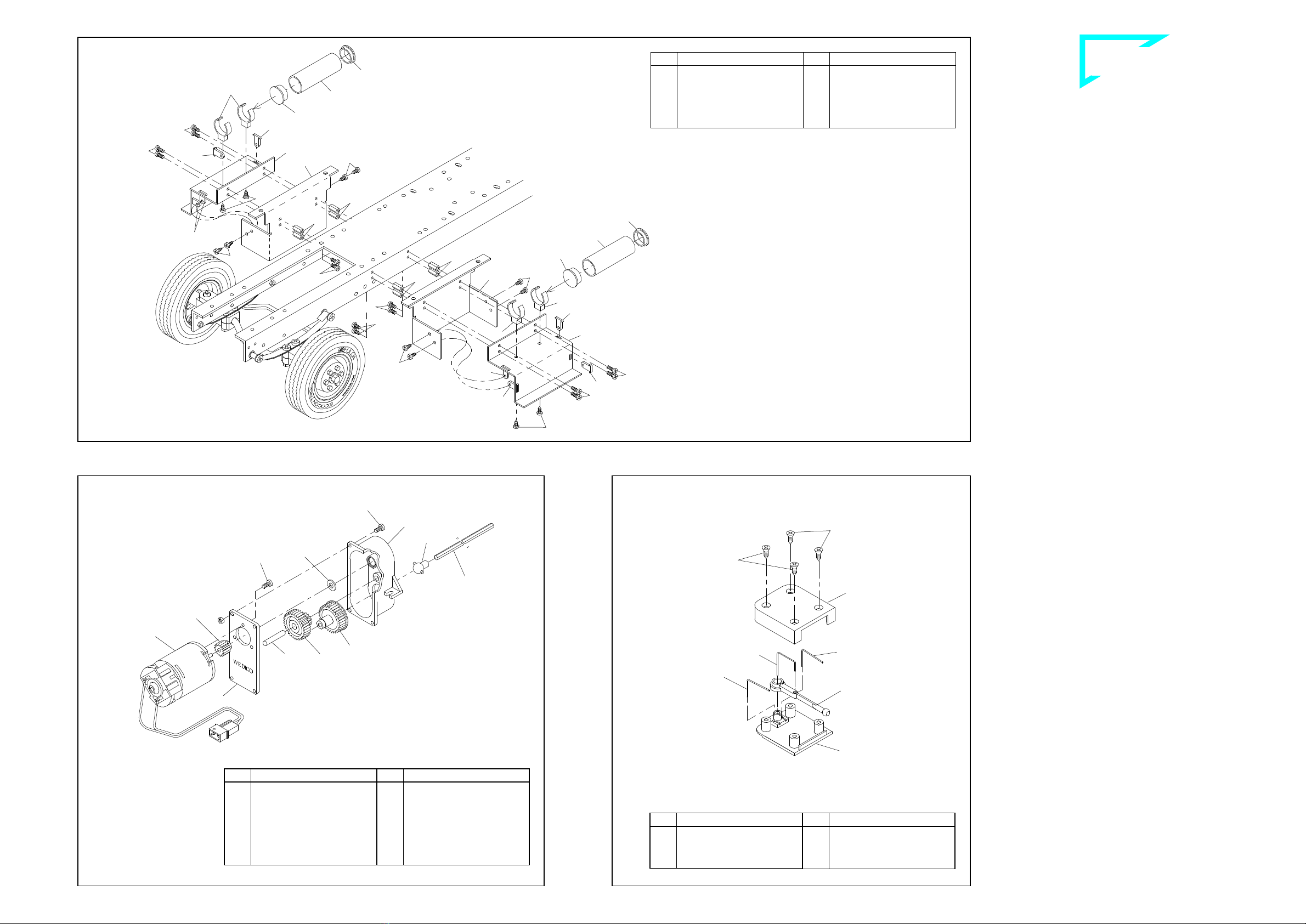
NN `çãéçåÉåíë=~íí~ÅÜÉÇ=íç=íÜÉ==
êÉ~ê=Ñê~ãÉ=ëÉÅíáçå=
11.1 Mounting the fifth-wheel components
Attach the spring 74 to the link lever 44 with a screw 1and M3 nut. Insert the
bar 72 into the opening from above, securing it from below with the link lever
and a tapping screw 21. Mount the fifth-wheel 71 from above, inserting the
feet into the slots in the frame. Slide the shaft 73 through the holes at the si-
de of the frame and the feet of the fifth-wheel, catching the free end of the
spring 74 between the feet when doing so. The shaft is secured with two re-
taining washers 25.


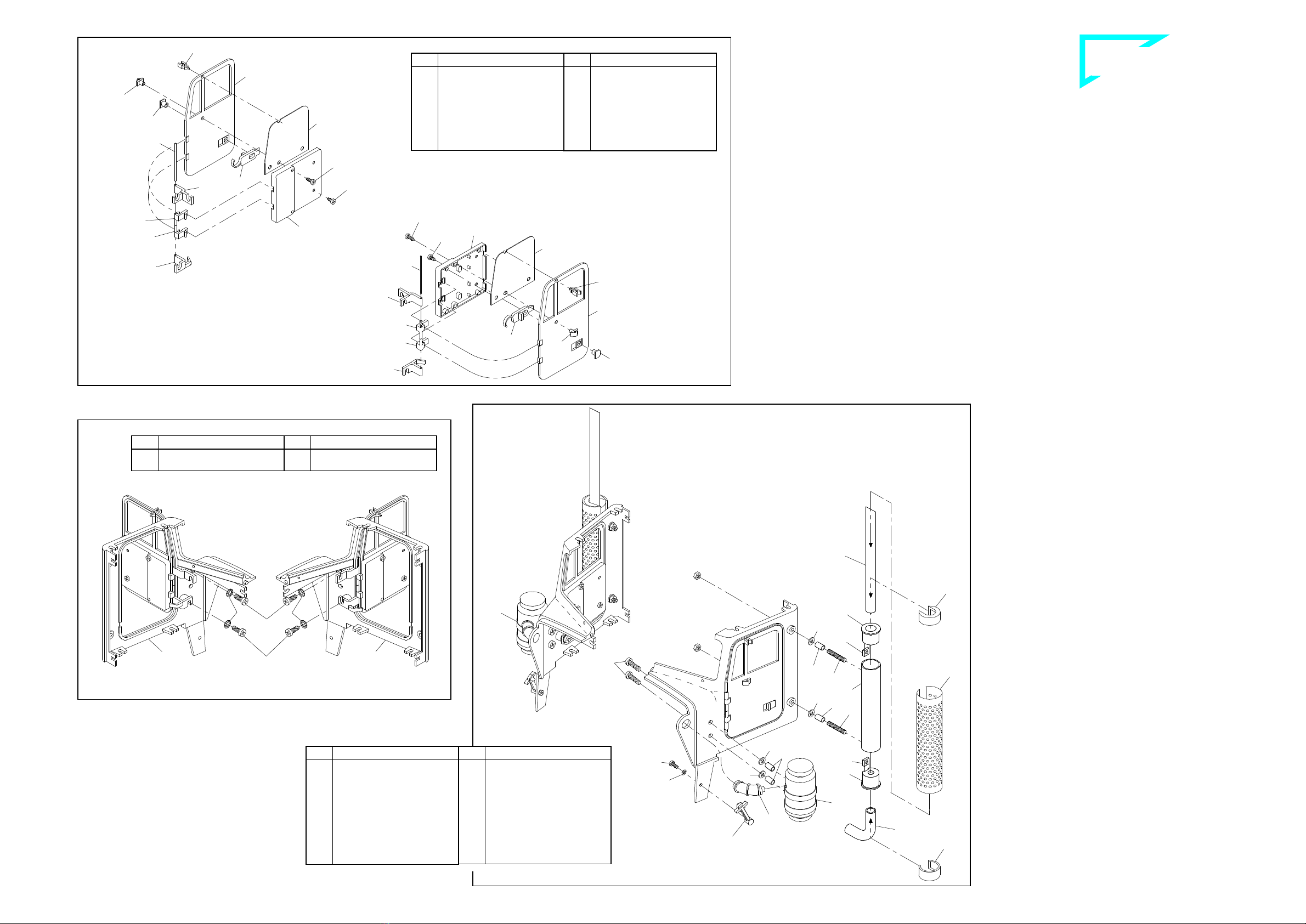
Please ensure when attaching the fifth-wheel that the ribbon cable with the
two circuit boards is located between the frame and the shaft (ill. 9).
11.2 Mounting the rear bumper assembly
First insert the bulbs 713 in the lamp caps 709 as shown in the figure. Now af-
fix the assembled caps to the rear bumper 47 using one each screw 57 and
M3 nut. From the rear insert the lenses into the bumper: outwards the blinker
lenses 341, inwards the rear light lenses 342. Attach the frame tail piece 46
underneath the frame using screws 1and M3 nuts. Then the bumper and
carrier plate 710 are set in front of the frame tail piece and attached with
screws 2and M3 nuts.


Take particular care that the bulb cables are not clamped between the
bumper and the frame tail piece; this could cause a short circuit!
Using two adhesive pads 655, affix the PCB support 723 on the front surface
of the carrier plate, centred and flush with the bottom edge.
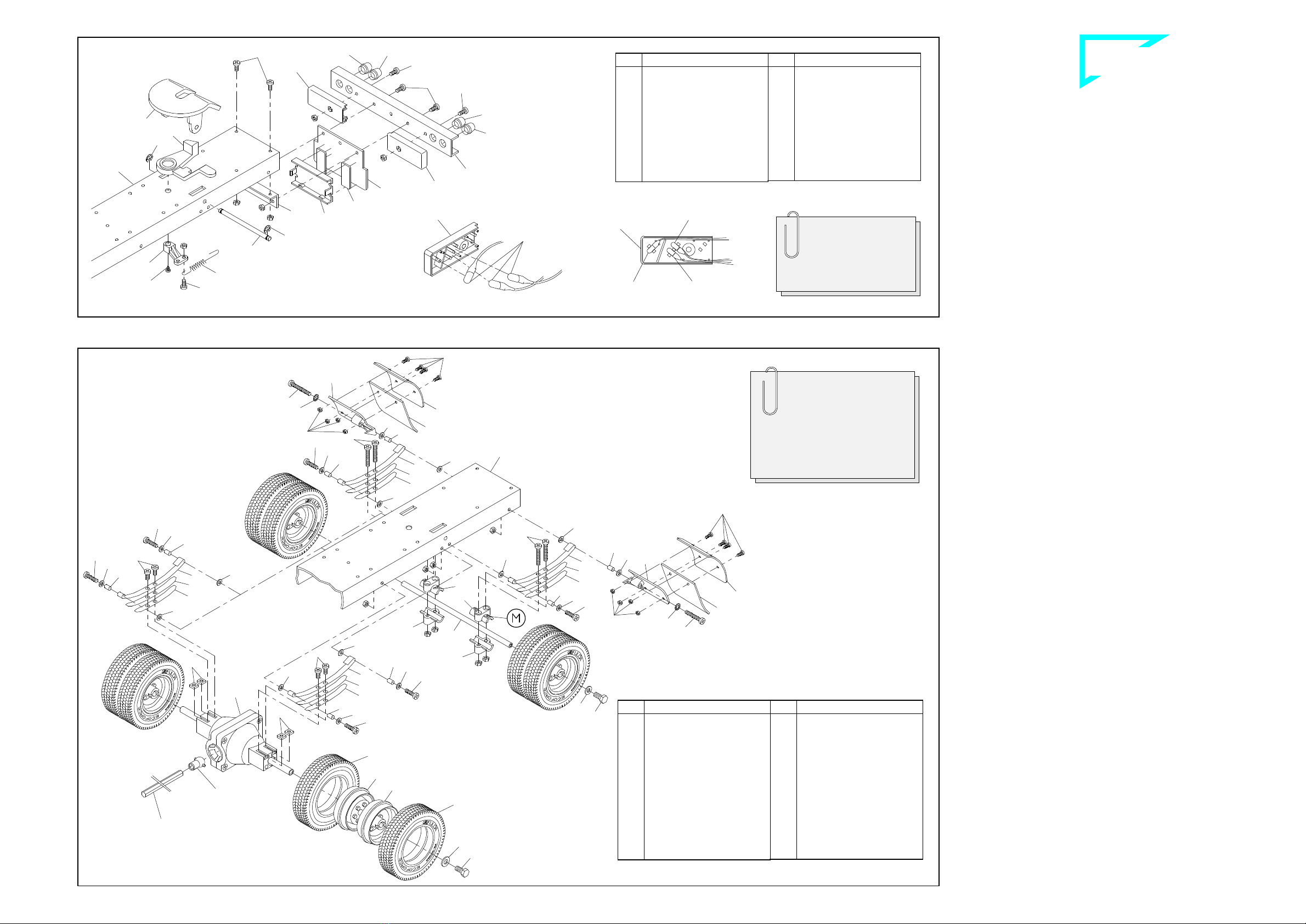
NO oÉ~ê=~ñäÉ=ëÉÅíáçå=
12.1 Mounting the mud guards
The mud guard support 715 is marked with an "X" and will later be mounted
on the passenger’s side, the mud guard support 716 marked "O" on the
driver's side. First attach to these supports the mud flaps 717 and the mud
guards 714 with four screws 114 and nuts 109 each. Then use screws 6, ser-
rated washers 15, bushings 26, two washers 13 and M3 nuts to attach the
supports to the holes at the rear of the frame.
12.2 Mounting the spring set and axle
Attach the open ends of the two long spring leaves 32 to the bushing and use
a screw 3, bushing 26, washer 13 and M3 nut to screw the closed end to the
frame. Press one each M3 nut into the hexagonal recess at the lower spring
carrier 70. The axle 68 can now be mounted together with the spring carriers,
one medium spring leaf 33 each, a short spring leaf 34 and screws 4.


Ensure that the end of the spring carrier 70 identified with an "M" is to-
ward the wheel.


The ribbon cable with the two lamp PCBs should be mounted when atta-
ching the rear axle and the differential!
12.3 Mounting the spring set and differential
First attach the long spring leaves 32 to the frame. Once you have inserted
one square nut 12 each into the grooves at the side of the differential the
springs can be attached with screws 1. The differential has two cams on the
wheel mounts; the grooves in the hubs are aligned exactly with these cams.
The wheels are affixed using screws 17 (which will cut their own threads) and
washers 20. Press the joint ball 64 into the joint socket at the mounted diffe-
rential.


In no case should you use an M3 screw more than 6 mm long to affix the
spring set as this would cause binding and damage the shafts on the dif-
ferential!
12.4 Mounting the wheels
Once you have mounted the drive axle tyres 1160 on the rims 52 the wheels
are mounted on the shaft, with the wheel nuts facing one another and the
chromed rims toward the outside; secure with a washer 20 and a screw 17.
The wheels should turn easily but there should not be too much play.
41-e.DOC / K-Peter Page 6
Rear axle section ill. 12
Components attached to the rear frame section ill. 11
Drive shaft
(grey)
(chromed)
Inserting the bulbs
Frame
Bulb for blinker
Bulb for
brake light
Bulb for rear light
Qty.
No. Assembly part
1 73
Shaft for fifthwheel
1 74
Draw spring
2 341
Blinker lens high, orange
4 342
Lens/rear light high, red
2 655
Adhesive pad,
double-sided
2 709
Lamp cap
1 710
Carrier plate for
support PCB
6 713
Bulb 3V
1 723
PCB support, small
Qty.
No. Assembly part
7 ---
Nut M3
3 1
Screw M3 x 6
2 2
Screw M3 x 8
1 21
Tapping screw 2.2 x 4.5
2 25
Retaining washer 3.2
1 44
Link lever
1 46
Frame tail piece
1 47
Bumper, rear
2 57
Screw M3 x 10
1 71
Standard fifthwheel
1 72
Bar for kingpin
Note!
The kit contains two
additional red lenses 342
for the US chassis version
equipped with red blinkers.
Qty.
No. Assembly part
4 52
Rim, grey
4 52
Rim, chromed
1 64
Ball joint
1 66
Standard differential,
mounted
1 68
Rear axle 144mm
4 70
Spring carrier, plastic
8 109
Nut M2
8 114
Screw M2 x 6
2 714
Mud guard
1 715
Mudguard support “X“
1 716
Mudguard support “O“
2 717
Mud flap
8 1160
Drive axle tyre “Ecoforce“
Qty.
No. Assembly part
12 ---
Nut M3
4 1
Screw M3 x 6
6 3
Screw M3 x 12
4 4
Screw M3 x 16
2 6
Screw M3 x 25
4 12
Square nut M3
16 13
Washer 3.2
2 15
Serrated washer 3.2
4 17
Hex head screw M4 x 8
4 20
Washer 4.3
8 26
Bushing 4 x 0.5 x 7
4 32
Spring long, “AF“
4 33
Spring medium, “AF“
4 34
Spring short, “AF“
709
713
709
For a better overview the il-
lustration is showing
an assembly without rear
bumper and fifth-wheel
Frame
`çãéäÉíÉ=háí=mÉíÉêÄáäí=
`çãéäÉíáçå=çÑ=~ëëÉãÄäó=Öêç éë
114
114
114
114
843
843
843
846
846
846
846
846
846
846
845
845
844
844
369
369
369
368
368
370
370
370
370
21
21
21
21
742 21
21
843
742
742
720
721
721
722
719
724
564
564
2
58
391
2
60
62
61
63
59
708
64
41-e.DOC / K-Peter Page 7
NP píÉéÄç~êÇ=ëÉÅíáçå=
First fix the threaded bushings 843 with screws 742 laterally onto the
sides of the frame and afterwards screw the bridging clamps 369
with screws 21 onto the stepboard plates 845. Into their slots pin the
plate connections 846, lay the plates onto the stepboards 844 and fix
them with screws 21 onto the stepboards. The right and the left step-
board are then secured with screws 114 onto the threaded bushings.
Into the case for air tank 368 press then on both sides each one co-
ver 370 and slide the case into the bridging clamps 369.
NQ jç åíáåÖ=íÜÉ=ãçíçê=~åÇ=ÖÉ~êÄçñ=
Use screws 2to bolt the gear cover 59 to the motor 708 (we supply
the white motor pinion 60 (14t.) already mounted to the motor shaft).
Before assembling the gearing lubricate the gears and shafts lightly
with Vaseline. Then clip the joint ball 64 in the gear wheel 62. Lay this
gear wheel, the double pinion 61 with shaft 63 and -not to forget!- the
shim 391 in the gear housing 58 and use screws 2and M3 nuts to
secure the gear housing to the cover.
NR ^ëëÉãÄäáåÖ=íÜÉ=ÄäáåâÉê=ëïáíÅÜ=
Slide two single-bent springs 721 into the corresponding holes and
slots in the base plate 720. Insert the double-bent spring 722 into the
two holes on the lever blinker switch 724 and then place the eye of
the lever over the boss on the base plate. The cover plate 719 is now
secured to the base plate with countersunk screws 564.
Stepboard section ill. 13
Assembling the blinker switch ill. 15Mounting the motor and gearbox ill. 14
Qty.
No. Assembly part
8 742
Screw M2 x 5
8 843
Threaded bushing M2 x 8
2 844
Stepboard Peterbilt
2 845
Stepboard plate
8 846
Connection stepboard
plate
Qty.
No. Assembly part
12 21
Tapping screw 2.2 x 4.5
8 114
Screw M2 x 6
2 368
Case for air tank
4 369
Bridging clamp
for air tank
4 370
Cover for air tank
Qty.
No. Assembly part
1 62
Gear wheel with joint
socket
1 63
Shaft 5 x 24 for gear 116
1 64
Ball joint
1 391
Shim 5 x 10 x 1
1 708
Bühler motor incl. 14
teeth pinion
1 1048
Drive shaft 300mm
Qty.
No. Assembly part
4 ---
Nut M3
7 2
Screw M3 x 8
1 58
Case for gear 116
1 59
Cap for gear 116
(1)
60
Motor pinion, white,
14teeth
1 61
Double pinion for gear
116
Qty.
No. Assembly part
2 721
Spring, single bent
1 722
Spring, double bent
1 724
Lever for blinker switch
Qty.
No. Assembly part
4 564
Countersunk tapping
screw 2.2 x 4.5
1 719
Cover for blinker switch
1 720
Base for blinker switch
1048
B-334-1
B-50-6
B-41-6
`çãéäÉíÉ=háí=mÉíÉêÄáäí=
`çãéäÉíáçå=çÑ=~ëëÉãÄäó=Öêç éë
2
13
655
723
929
655
760 4
13
2
2
13
13
21
21
21
21 848
849
849
849
849
850
850
850
850
NS jç åíáåÖ=íÜÉ=ÇêáîÉ= åáí=~åÇ=íÜÉ=ëíÉÉê~ÖÉ=
16.1 Gearbox
Once assembled, the gearbox is inserted from above into the ope-
ning in the frame and secured at the sides with screws 2, washers 13
and M3 nuts. At the same time the drive shaft 1048 (see ill. 15) is in-
serted at the joint balls between the gearbox and the differential.
16.2 Mounting the servo unit
Start by screwing on the servo supporting angle 760 underneath to
the frame; for this purpose use screws 2and nuts M3. Accordingly to
the drawing add now two screws 4with washers 13 and nuts M3 to
the steering servo. Finally use washers 13 and nuts M3 to fix the
complete unit onto the servo supporting angle.
16.3 Mounting the PCB support
Use two adhesive pads 655 to affix the PCB support 723 in front of
the gearbox under the frame.
16.4 Attaching the blinker switch
Attach the blinker switch with two adhesive pads 655 that way onto
the steering servo, that the clamp-type connector 929 lays in front of
the vertical leg of the frame tail piece (please refer to point 18.2).
NT ^ëëÉãÄäó=çÑ=íÜÉ=Å~Ä=êÉ~ê=é~åÉä=
Into the four slots of the rear panel 848 lay each one bar 849. From
inside press onto these outer bars each one bar 850; fix them with
screws 21.
41-e.DOC / K-Peter Page 8
Assembly of the cab rear panel ill. 17
Installation of drive unit and steerage ill. 16
steering servo
(not incl. in the kit)
Ribbon cable from
the switch panel
fully assembled
blinker switch
Moment of torsion of the servo should
be at 20 Ncm. The servo supporting angle
will fit servos with the following data:
L x W x H:........................41 x 20 x 38 mm
Gauge for screwing ....................48 ±2 mm
Qty.
No. Assembly part
1 723
PCB support, small
1 760
Servo angle 1, small
1 929
Clamp-type connector, 3-
pole
Qty.
No. Assembly part
10 ---
Nut M3
4 2
Screw M3 x 8
2 4
Screw M3 x 16
10 13
Washer 3.2
2 655
Adhesive pad, double-
sided
Qty.
No. Assembly part
4 849
Bar (outside), rear panel
4 850
Bar (inside), rear panel
Qty.
No. Assembly part
8 21
Tapping screw 2.2 x 4.5
1 848
Rear panel, Peterbilt
green
brow
n
white
B-41-7
B-220-9
`çãéäÉíÉ=háí=mÉíÉêÄáäí=
`çãéäÉíáçå=çÑ=~ëëÉãÄäó=Öêç éë
1
1 1
1
775
775
776
776
2
15
109
847
949
46
17mm
41-e.DOC / K-Peter Page 9
Attachment of the cab and the hood onto the chassis ill. 18
NU ^íí~ÅÜãÉåí=çÑ=íÜÉ=Å~Ä=~åÇ=íÜÉ=ÜççÇ=çåJ
íç=íÜÉ=ÅÜ~ëëáë=
18.1 Attachment of the cab and the hood
Fix the cab onto both steps with screws 1, serrated washers 15 and
nuts M3. Add the premounted rear panel onto the rear of the cab.
Now use screws 776 and nuts 109 to attach the support for the radia-
tor 775 -at the front on the right side- onto the chassis frame.
Pin then the right hinge pin of the tilting hook on the radiator into the
fore hole of the premounted support 775. Lay now the left support
775 onto the left hinge pin of the tilting hook of the radiator and fix
the support with screws 776 and nuts 109 onto the chassis. Tilt the
hood towards the front units of the cab and leave the locks (locking
device 834) catching the holes of the hood.
18.2 Attachment of the bumper


When mounting the Bulbar, Art.-No. 408: Replace screws 11 by
screws 949 (included with this kit).
Mount first the frame tail piece 46 with two screws 2and four nuts
M3 from underneath onto the frame. Afterwards fix two screws 11
with nuts M3 onto the bumper 847, and behind, at a distance of
17mm, mount one each additional nut. Using another set of these
nuts (each one of them), fix the bumper onto the frame tail piece.
premounted
rear panel
tilting hook
of the ra
diator
Qty.
No. Assembly part
4 109
Nut M2
2 775
Support, radiator Peterb.
4 776
Countersunk screw
M2 x 6
1 847
Bumper front, chromed
2 949
Screw M3 x 35
Qty.
No. Assembly part
14 ---
Nut M3
4 1
Screw M3 x 6
2 2
Screw M3 x 8
2 11
Screw M3 x 30
4 15
Serrated washer 3.2
1 46
Frame tail piece
B-41-8
`çãéäÉíÉ=háí=mÉíÉêÄáäí=
`çãéäÉíáçå=çÑ=~ëëÉãÄäó=Öêç éë
397 24
856
24
115
397
24
24
115
109
114
114
109
109
114
858
858
863
21
24
24
24
24
21
24
21
109
857
857
860
860
859
859
858
858
861
855
24 109
24
390
1264
568
1265
701
210
560
630 629
NV mêÉé~ê~íáçå=çÑ=íÜÉ=päÉÉéÉê=í~áä=Çççê=
Pin the toggle switches of the switch panel through the holes provi-
ded in the tail door 1265, and secure them from behind with knurled
nuts 210. Clip those jack bushes 701 coming off the PCB into the
corresponding holes in the tail door. From behind pin on the insula-
ting discs red 629 and black 630 and secure the unit with knurled
nuts 560. The black insulating disc serves to identify the jack with the
two black conductors!


When installing the jack bushes into the tail door make sure that
their centre solder eyes are facing outwards.
Finally add the label indicating the switches beneath the toggle swit-
ches (please follow ill. 23b).
OM ^ëëÉãÄäó=çÑ=êççÑI=Ñäççê=~åÇ=Çççêë=
20.1 Antenna socket
Affix the components for the antenna socket 568 as shown in the il-
lustration. Please note that the antenna cable from the remote con-
trol receiver will have to be soldered to the antenna socket.
20.2 Floor and front panel
Attach the lock 861 for the tail door with screw 114, washer 24 and
nuts 109 from underneath onto the floor 855. From top add then the
hinge bushings 858 onto the floor and fix them from underneath with
screws 21. Now use two screws 397 and washers 24 to mount the
front panel 856 onto the floor.
20.3 Side doors and roof
Slide each one hinge pin 859 through the holes of the bent hinge
strut of the side doors and, accordingly to the illustration, lay one
each spring wire 860 around the hinge pins. Thereby insert the lower
end of the spring wires into the second hole of the bottom hinge
struts.
Take now the right side door and press the upper end of the hinge
pin into the outer hole and the upper end of the spring wire into the
inner hole of the roof. Fix then the roof with screws 115, washers 24
and nuts 109 onto the front panel. Thereby you have to insert the lo-
wer end of the hinge pin into the hole of the premounted hinge bus-
hing 858.
Now attach the left side door with the hinge pin and the spring wire
by the same way onto the roof and the hinge bushing; for this purpo-
se lightly lift the roof.
20.4 Tail door
Now both hinge bushings 858 have to be attached with screws 114,
washers 24 and nuts 109 onto the tail door. Slide the hinge pin 863
through the holes of the hinge bushings. Fix the door thus prepared
onto the lower hinge bushing with screw 21 onto the floor and insert
the upper end of the hinge pin into the hole of the roof.
41-e.DOC / K-Peter Page 10
Preparation of the Sleeper tail door ill. 19
Assembly of roof, floor and doors ill. 20
to front PCB
Switch panel
to battery
to blinker switch
to rear PCB
to terminal strip
for roof lamps
to charging cable
to speed controller
Tail door
For a better overview the cables of the switch panel
have not been considered in this drawing
M1:1
859 Hinge pin
860 Spring wire /door
863 Hinge pin for tail door
Qty.
No. Assembly part
2 701
Jack bush 3.5mm
1 1265
Tail door, Sleeper,
Compl. kit Peterbilt “C“
1 ---
Sticker for switch
Qty.
No. Assembly part
4 210
Knurled nut M5
2 560
Knurled nut M6
1 629
Insulating disc, red
1 630
Insulating disc, black
Qty.
No. Assembly part
2 857
Side door, Sleeper
Peterbilt
4 858
Hinge bushing, doors
2 859
Hinge pin ∅1.5 x 95
2 860
Spring wire ∅1 x 98
1 861
Lock for tail door
1 863
Hinge pin for tail door
∅1,5 x 101
1 1264
Roof Sle
eper, Compl. kit
Peterbilt “C“
Qty.
No. Assembly part
3 21
Tapping screw 2.2 x 4.5
11 24
Washer 2.2
5 109
Nut M2
3 114
Screw M2 x 6
2 115
Screw M2 x 8
1 390
Welsh plug, oval
2 397
Tapping screw 2.2 x 6.5
1 568
Roof, Sleeper Peterbilt
1 855
Floor, Sleeper Peterbilt
1 856
Front panel, Sleeper Pe-
terbilt
B-41-9
B-41-10
At this point do
not lead any
wire through!