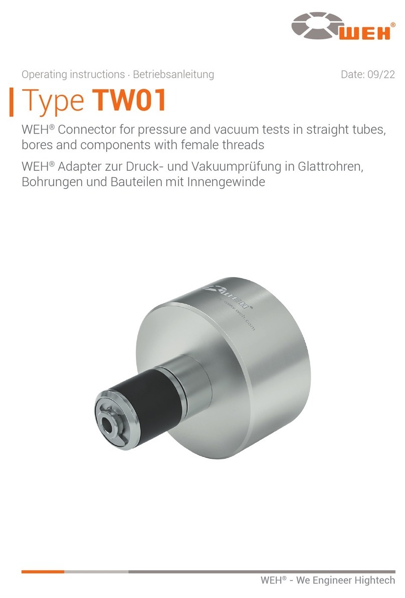
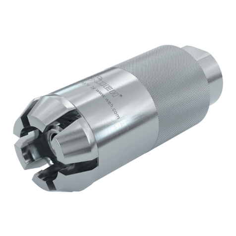
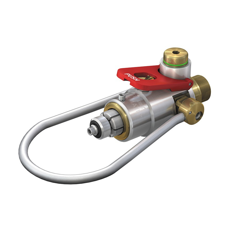
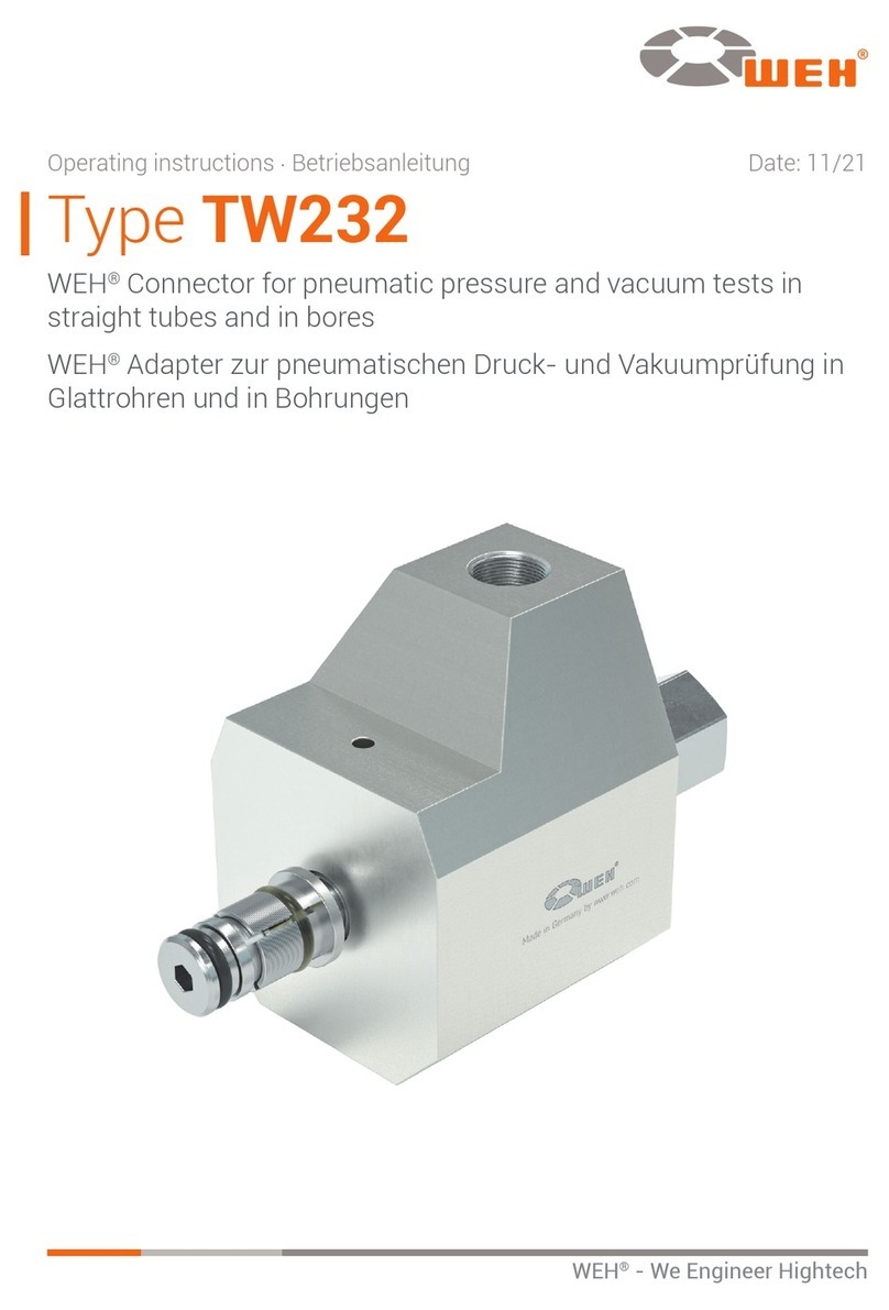
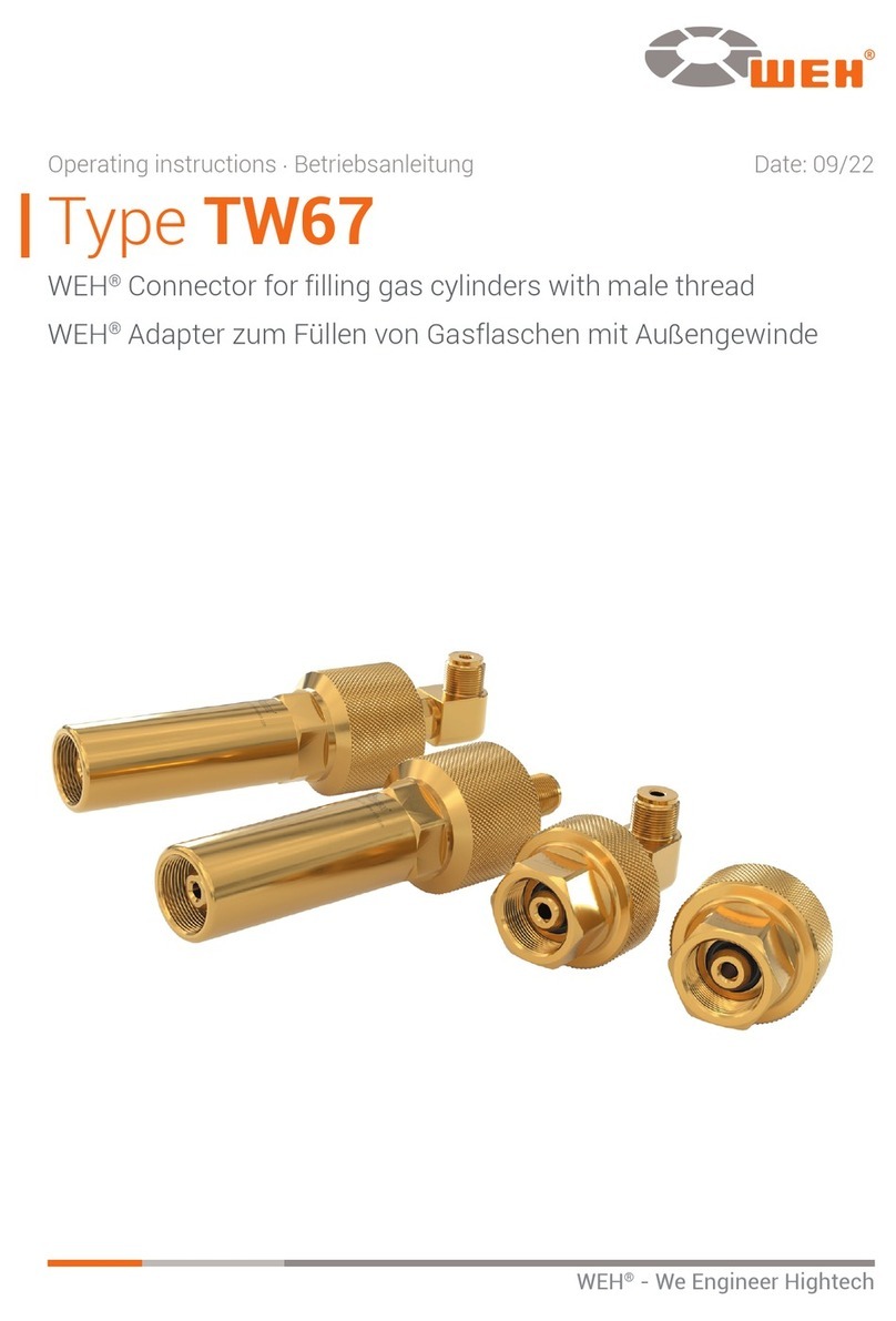
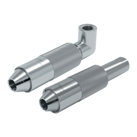
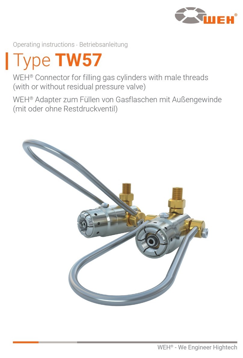
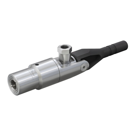
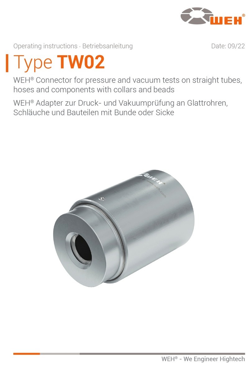
Weh TW54 User manual

WEH®- We Engineer Hightech
Type TW54
Operating instructions ⋅Betriebsanleitung
WEH®Connector for filling gas cylinders with
female threads (with or without residual pressure valve)
WEH®Adapter zum Füllen von Gasflaschen mit
Innengewinde (mit oder ohne Restdruckventil)


Die deutsche Version ist das Original.
Hersteller: WEH GmbH Verbindungstechnik - im Nachfolgenden „WEH“ genannt.
LANGUAGES
TYPE TW54 � � � � � � � � � � � � � � � � � � � � � � � � � � � � � � � � � � � � � � � � � � � � � � � � � � � � � 4
WEH®Connector for filling gas cylinders with
female threads (with or without residual pressure valve)
TYP TW54 � � � � � � � � � � � � � � � � � � � � � � � � � � � � � � � � � � � � � � � � � � � � � � � � � � � � � 32
WEH®Adapter zum Füllen von Gasflaschen mit
Innengewinde (mit oder ohne Restdruckventil)
AE
DE
The German version is the original.
Manufacturer: WEH GmbH Precision Connectors – hereinafter referred to as “WEH”.

CONTENTS
1. INTRODUCTION 6
1.1 For your guidance 6
1.2 General information 7
1.3 Warranty and liability 7
1.4 General safety instructions 8
1.5 Definition of qualified personnel 8
2. INTENDED USE 9
3. PRODUCT OVERVIEW / PRODUCT DESCRIPTION 10
4. TECHNICAL DATA 13
5. STORAGE 14
5.1 Safety instructions for proper storage 14
5.2 Storage 15
6. REQUIRED TOOLS 15
7. INSTALLATION 16
7.1 Safety instructions for installation 16
7.2 Installing the media hose line 17
7.3 Checking the connection for leaks 17
Type TW54
WEH®Connector for filling gas cylinders with
female threads (with or without residual pressure valve)
MD-10017-L51-R2.1.0-03
Page 4
Operating instructions
AE

The German version is the original.
Manufacturer: WEH GmbH Precision Connectors – hereinafter referred to as “WEH”.
8. OPERATION 18
8.1 Safety instructions for operation 18
8.2 Connection 19
8.3 Disconnection 22
9. INSPECTION | MAINTENANCE 23
9.1 Safety instructions for inspection and maintenance 23
9.2 Maintenance intervals 24
9.3 Overview of minimum intervals for inspection and maintenance 25
9.4 Maintenance 26
10. LUBRICATION 28
10.1 Safety instructions for lubrication 28
10.2 Lubrication 28
11. TROUBLESHOOTING 29
12. DISPOSAL 31
13. ACCESSORIES | SPARE PARTS 31
MD-10017-L51-R2.1.0-03 Page 5
Operating instructions AE

1. INTRODUCTION
Dear Customer,
Thank you for deciding to use our products.
The WEH®TW54 Connector has been specially developed for filling gas cylinders
(200 bar and 300 bar) with female threads, with or without residual pressure valve.
Observe and follow all instructions and warnings in these operating instructions�
Non-observance may result in personal injury and/or property damage�
1�1 For your guidance
The markings and symbols contained in these operating instructions have the following
meanings:
- items are indicated by a dash
Îcalls for action are indicated by an arrow
Figures
The illustrations and/or images used in these operating instructions are particularly provided
for illustrative purposes only and may differ in some details from the actual product. For
binding information, please refer to your individual orders.
Abbreviations
For explanation of abbreviations and definitions of terms see Technical Appendix of the
corresponding catalog or www.weh.com
Definition of signal words
Caution: Sections marked ‘Caution’ warn you of hazards that could result in minor,
usually reversible, personal injury if you do not comply with the instruction.
Attention: Sections marked ‘Attention’ warn you of situations that could lead to property
damage and disruptions in operation if you do not comply with the instruction.
Note: Sections marked ‘Note’ indicate that malfunctions in operation may occur if you
do not comply with the instruction.
Please note: Sections marked with ‘Please note’ provide you with additional information
for smooth operation.
MD-10017-L51-R2.1.0-03
Page 6
Operating instructions
AE

1�2 General information
ÎFirst read these operating instructions to avoid misuse and resulting damage.
- In these operating instructions you will find all the necessary information and
instructions for the WEH®Product.
ÎThen check the contents of your delivery. Each delivery must contain:
- a delivery note
- an original WEH Test report (not applicable to spare parts)
- WEH operating instructions
ÎIf any documents are missing, please contact WEH or your responsible distributor.
1�3 Warranty and liability
- Our General Terms and Conditions apply.
ÎRead these operating instructions and safety instructions carefully and follow the
information contained therein.
- The information in these operating instructions reflects to the state of knowledge at
the time of printing. Failure to comply may void the warranty. Any side agreements to
these operating instructions require the written approval of the Head of the Quality
Department at WEH.
- Violation of these operating instructions result in the lapse of all warranty claims.
WEH will accept no liability for consequential damage, in particular damage due to
personal injury and/or other legal interests.
Caution: WEH®Products may only be repaired by WEH.
ÎContact WEH or the responsible distributor if the WEH®Product requires
maintenance. Special maintenance work that may be performed by the operator is
described in these operating instructions and is specially marked.
ÎOnly use original WEH®Spare parts. These are exactly suited to the intended
application and subject to strict quality controls.
- You are responsible for the correct operation of the replacement or repair. WEH is not
responsible for the performance or any damage and/or losses arising from it. WEH
assumes no warranty, product liability or other liability for any replacement or repair
performed by you or a third party. If you or a third party does not have the necessary
skills and qualification for proper performance, you must refrain from performing
replacement or repair. Otherwise, there is a particular risk of endangering yourself
and third parties.
MD-10017-L51-R2.1.0-03 Page 7
Operating instructions AE

1�4 General safety instructions
ÎAlways comply with all applicable local, national and international requirements,
stipulations, decrees, laws, standards, provisions, directives, norms, regulations,
prohibitions and instructions as well as all applicable industrial, quality and technical
standards. In particular, make sure that you and all users comply with the applicable
requirements related to occupational health and safety as well as product safety
requirements and that all required permissions, certificates and approvals have been
obtained.
ÎThese operating instructions should be provided to anyone responsible for the
installation, operation and maintenance of this WEH®Product.
ÎContact WEH before using the WEH®Product if the instructions in these operating
instructions are unclear in any way.
ÎTake appropriate safety measures if operating conditions exist that could endanger
the user.
ÎIn case of any damage that may affect the proper functioning of the WEH®Product, do
not use the WEH®Product until the situation has been clarified. Disassembly of the
WEH®Product may only be performed by WEH.
ÎComply with the assembly data indicated in these operating instructions. Tightening
with higher torques/assembly turns can result in damage or even fractures when the
system is pressurized.
ÎDo not use any auxiliary materials or cleaning agents other than those indicated in
these operating instructions. Using other auxiliary materials or cleaning agents may
cause damage to the WEH®Product or to downstream components.
- WEH is not responsible for damage caused by external forces or other external
influences.
- It is assumed that only transport and storage facilities suitable for the storage of the
WEH®Product are used.
1�5 Definition of qualified personnel
- Qualified personnel, as defined by these instructions, are persons who, based on
their professional training, their knowledge (including the relevant standards and
regulations), experience and manual skills, can independently assess and properly
perform assigned work tasks (in conjunction with WEH®Products) and can thus
independently recognize and prevent potential dangers at an early stage.
MD-10017-L51-R2.1.0-03
Page 8
Operating instructions
AE

2. INTENDED USE
- The WEH®TW54 Connector has been specially developed for filling gas cylinders
with female threads, with or without residual pressure valve. The connector comes in
many different sizes and forms.
- This WEH® Connector has been specially developed for your application and
requirements that you specified when placing your order. The connection only works
properly together with your connection or medium and may only be attached to this
connection, or may only be operated using this medium. Operation with a mixture of
media can lead to damages due to residue or contamination, particularly in combination
with oxygen. For this reason, make sure that the necessary framework conditions
(e.g. cleanliness) are met for operation with the respective medium.
- The WEH®Connector is not suitable for emptying gas cylinders under pressure.
ÎAlways ensure that the WEH®Product is used only within the range of its intended use.
Please note in particular the technical data of the WEH®Product in Chapter 4 as well
as the marking on the WEH®Product itself.
- This WEH®Product is generally classified as pressure accessory in accordance
with Article 2 (5) of the Pressure Equipment Directive 2014/68/EU and is
considered to be similar to piping. This WEH®Product may not be used as safety
accessory. Furthermore, it is pointed out, that this WEH®Product is designed and
placed on the market in accordance with the requirements of Article 4 (3) of the
Pressure Equipment Directive 2014/68/EU. The assessment with regard to a
different classification can, however, be made on request.
Caution: Any use beyond the scope of application is considered as unintended use
and may result in personal injury and/or property damage.
MD-10017-L51-R2.1.0-03 Page 9
Operating instructions AE

3. PRODUCT OVERVIEW / PRODUCT DESCRIPTION
Product description
TW54 with spring-loaded residual pressure valve pin and bail actuation
Pos� Description
1 Bail actuation
2 RPV pin
3 Front part
4 Adjustment screw
5 Safety peg
7 Front seal
Definition of ports
B1 Media inlet
1 2 3 4
5
7
MD-10017-L51-R2.1.0-03
Page 10
Operating instructions
AE

TW54 with spring-loaded residual pressure valve pin, bail actuation, flexible wire rope
and locking device
Pos� Description
1 Flexible wire rope
2 RPV pin
3 Front part
4 Adjustment screw
5 Safety peg
6 Bail actuation
7 Front seal
8 Locking device
Definition of ports
B1 Media inlet
2 3 4
5
6
8
1
7
MD-10017-L51-R2.1.0-03 Page 11
Operating instructions AE

TW54 with spring-loaded residual pressure valve pin and actuation lever
Pos� Description
1 Actuation lever
2 RPV pin
3 Front part
4 Adjustment screw
5 Safety peg
7 Front seal
Definition of ports
B1 Media inlet
7
2
3
4
5
1
MD-10017-L51-R2.1.0-03
Page 12
Operating instructions
AE

4. TECHNICAL DATA
Please note: Depending on the application, the technical data of your WEH®Product
may differ from these operating instructions. Please therefore observe the marking on
the WEH®Product itself.
Characteristics Basic version
Pressure range PN = 200 bar | PS = 250 bar*
PN = 300 bar | PS = 375 bar*
Temperature range +5°C to +80°C
+5°C to +60°C (O2)
ConnectionA Female thread connection based on the relevant country standard
e.g. DIN, CGA, BS, NF etc.
Medium** Nitrogen, oxygen, CO2, air, noble gases, mixed gases, medical gases
Part materials Wear-resistant stainless steel, corrosion-resistant surfaces, brass
Sealing materials According to gas type
Design*** With or without RPV pin
Actuation*** Manual actuation via bail actuation, locking device etc.
Conformity /
Tests /
Approvals
- Adiabatic ignition test completed
*Please observe the pressure limits specified in the relevant cylinder valve standard.
These values may be lower than the max. allowable operating pressure of the WEH®Product.
** Other gases possible depending on the order confirmation
***depending on the application
MD-10017-L51-R2.1.0-03 Page 13
Operating instructions AE

5. STORAGE
5�1 Safety instructions for proper storage
ÎMake sure that you always comply with these following safety instructions and
storage time.
Attention: Improper storage of the WEH®Product can significantly reduce the
maximum service life.
ÎProtect the WEH®Product against damage, contamination, inappropriate storage
and excessive temperature fluctuations.
ÎStore the WEH®Product, the accessories and spare parts in the original packaging
until they are used for the first time and during periods when they are not being used.
ÎStore the WEH® Product within a temperature range of +5 °C to +80 °C (+5 °C to
+60°C for O2). Storage temperatures outside this range may affect the service life of
the WEH®Product.
ÎDo not store the WEH®Product in the vicinity of heat sources. Avoid humidity and
condensation. The ideal relative air humidity for storage is approx. 65%.
ÎDo not store the WEH®Product together in the same space with solvents, chemicals,
acids, fuels or disinfectants.
ÎProtect the WEH®Product against light (especially against direct sunlight), oxygen,
ozone, heat, UV rays, solvents and other negative environmental influences. The
service life of parts made of elastomer or plastic may be substantially reduced by
such environmental factors.
ÎDo not stack WEH®Products. For storage and retrieval, follow the first-in-first-out
(FIFO) principle.
MD-10017-L51-R2.1.0-03
Page 14
Operating instructions
AE

5�2 Storage
ÎFollow the safety instructions in Chapter 5.1 and observe the following storage
times. The appropriate storage period applies from the date of delivery (i.e. the date
of invoicing or goods issue date as recorded by WEH or its sales partner). If the
WEH®Product is installed in a complete system, the storage time depends on the
component with the shortest storage time.
Up to 3 years
ÎBefore use, check the surfaces of the external seals for cracks.
Attention: Any elastomer seals with fine cracks on the surface must
be replaced.
Note: If you should have any doubts about the aging state of the
stored WEH® Product, please contact WEH.
Attention: Before commissioning, check the WEH® Product for leak
tightness. On this topic, see Chapter 7. Installation on page 16.
> 3 years - Before use, all elastomer seals must be replaced.
ÎFor this, send the WEH®Product to WEH for maintenance.
6. REQUIRED TOOLS
Part no� Description Installation
Mainte-
nance &
Lubrication
-- Suitable open-ended spanner
(suitable for the relevant spanner widths) X
-- Suitable calibrated torque wrench
(suitable for the corresponding torque) X
W136538 WEH®O-ring picker set*X
E99-44923 WEH®Lubricant X
*The WEH® O-ring picker is manufactured from plastic and has to be considered as a
consumable product.
MD-10017-L51-R2.1.0-03 Page 15
Operating instructions AE

7. INSTALLATION
7�1 Safety instructions for installation
ÎCheck the information provided in these operating instructions and the label on the
WEH® Product. The information must conform to your application.
ÎOnly connect the WEH®Product to faultless connections.
ÎCheck the WEH®Product for transport damages, contamination and other damage. If
you should detect anything wrong with the WEH®Product, it may no longer be used.
Replace the WEH®Product or send it to WEH for maintenance.
ÎRemove transport securing devices (such as protection caps) before installing the
WEH®Product. Transport securing devices serve the purpose of protecting the
product and connection ports during transport and storage. The transport securing
devices are not, for example, designed to withstand pressure or to be used as plugs.
ÎEnsure that the system is depressurized. Installation must only be effected in
depressurized condition.
ÎAvoid using excessively short media hose lines and narrow bending radii. Lateral
forces may cause leakages or damage to components and make it more difficult to
attach the WEH®Connector properly.
ÎUse arrestor cables, partitions, etc. for additional safety where being used for
hazardous applications or under hazardous conditions.
ÎBefore installation, check if the counterparts are designed to withstand the assembly
data (see Chapter 7.2 Installing the media hose line) that WEH determined for this
WEH®Product.
Note: The assembly data (torques, assembly turns etc.) are values which apply
exclusively to the components delivered by WEH.
ÎPosition the WEH®Product in your system so that the red marking on the front part
(pos. 3) is visible. This must be visible for the operator.
MD-10017-L51-R2.1.0-03
Page 16
Operating instructions
AE

7�2 Installing the media hose line
Please note: Subsequent mentions of descriptions and position numbers refer to
Chapter 3. Product overview / product description on page 10.
ÎUnscrew the protection cap from the port.
ÎWhen mounting the filling hose, hold an open-ended
spanner against the spanner flat AF(1) (Figure 1).
ÎScrew the media inlet "B1" pressure-tight onto the
connection port of the filling hose (Figure 1).
For the tightening torque, please refer to the table below.
Note: For NPT thread, first wrap Teflon tape round the
tapered screw fitting (1.5layers). Screw it finger-tight into
the port and install it in accordance with the information in
the table below.
Connections
male thread
Torque
G thread
Assembly turns
NPT thread*
NPT 1/4" -- 2.0–3.0
NPT 3/8" -- 2.0–3.0
M16x1.25 20 Nm ± 2 Nm --
W21.8x1/14" 20 Nm ± 2 Nm --
G1/4" 30 Nm ± 2 Nm --
G3/8" 40 Nm ± 2 Nm --
G1/2" 50 Nm ± 2 Nm --
* One turn corresponds to 360°
ÎPlease note the connection size marked on your product.
- Other connection sizes are available on request.
7�3 Checking the connection for leaks
ÎConnect the connector to a closed cylinder valve.
ÎSlowly apply the operating pressure to the connector and media hose line.
Caution: The cylinder valve must be closed/locked.
ÎCheck the connector, the connection to the media hose line and the connection to
the cylinder valve for leak tightness.
Figure 1
AF(1)
B1
MD-10017-L51-R2.1.0-03 Page 17
Operating instructions AE

8. OPERATION
8�1 Safety instructions for operation
Please note: Subsequent mentions of descriptions and position numbers refer to
Chapter 3. Product overview / product description on page 10.
ÎApply pressure to the WEH®Connector only once it has been connected to a cylinder
valve.
ÎDo not use excessive force when actuating.
ÎFollow the steps in exactly the right order when connecting and disconnecting the
WEH®Connector.
ÎAttach and detach the WEH®Connector only when it is not under pressure.
Note: The connector is equipped with a safety peg (pos. 5) The safety peg protrudes
if subjected to pressure of between 15bar and 20bar. This will cause it to block the
actuator. As a result, the connector cannot be disconnected under pressure. Once
the filling operation has finished and the system is fully depressurized, the safety
peg will retract again. Then you can easily return the actuator to its initial position.
Unlocking the actuator before the equipment is fully depressurized and before the
safety peg has fully retracted can result in damage to the safety peg.
ÎConnect the WEH®Connector only onto cylinder valves in perfect working order.
ÎAlign the WEH®Connector correctly with the test piece to prevent damage to the
front seal caused by any sharp edges that the test piece may have.
ÎOnce the connection has been made, always test the connection by tugging a little
on the WEH®Connector to make sure that is fully engaged and that the clamping
jaws are gripping correctly before introducing the pressurized test medium.
ÎThe clamping jaws of the WEH®Connector are designed to grip the cylinder valve
firmly. Keep fingers and other objects away from the clamping jaws when actuating
the connector.
Caution: Possible consequences of failing to observe this instruction may include:
– Risk of fingers being crushed while connecting
– Risk of personal injury and damage to property by parts that may become
detached under high pressure
– Risk of personal injury by media escaping at high pressure
– Risk to human safety by hoses not being secured
ÎKeep the WEH®Connector free of oil, grease and dust.
Attention: Contamination in the gas channel can cause oxygen combustion.
MD-10017-L51-R2.1.0-03
Page 18
Operating instructions
AE

ÎThe WEH®Connector is not fitted with an integrated shut-off valve and thus will not
prevent loss of medium in case of improper connection or after disconnecting. Apply
pressure to the connector only once it has been properly connected. It is important
to disconnect the connector only under absolutely safe conditions. In particular, the
connector must be fully depressurized during the connection process.
8�2 Connection
Connecting a TW54 with bail actuation and actuation lever
ÎFold the actuation unit (pos. 1) upwards (Figure 2).
The clamping jaws will close together.
ÎInsert the connector loosely and straight into the cylinder
valve until a noticeable seal contact has been established
(Figure 3). Doing so will prevent any damage to the front
seal caused by any sharp edges on the cylinder valve and
ensure a correct connection.
Attention: Make sure that the connector is pressed onto
the cylinder valve until a noticeable seal contact has been
established.
Note: Insert the connector with RPV pin into the cylinder
valve until the RPV pin is pushed open in the cylinder valve
and the sealing piston creates a seal.
ÎFold the actuation unit (pos. 1) downwards. It must be
possible to lower the bail/lever easily and without any
force. In its end position, the actuation unit must be
below the horizontal of the connector (Figure 4). The red
marking on the front part (pos. 3) must disappear under
the housing and must no longer be visible (Figure 5 and
Figure 6).
Attention: If the clamping jaws do not grip correctly in the
cylinder valve, if the actuation unit is not below the
horizontal or if the red marking on the front part is visible,
then the connector is not properly connected. The
connector may spring out of place and medium may
escape.
Figure 2
Figure 3
Figure 6Figure 5Figure 4
MD-10017-L51-R2.1.0-03 Page 19
Operating instructions AE

ÎPull lightly on the connector in the direction opposite that of the connection to make
sure that the connector is firmly in place.
- The connector is now connected pressure-tight to the cylinder valve.
ÎOpen the cylinder valve.
ÎTo start the filling procedure, apply pressure to media inlet “B1”.
Attention: The safety peg (pos. 5) at the connector must be extended after pressure
is applied. The actuator is blocked, the connector cannot be disconnected when it is
pressurized.
Connecting a TW54 with bail actuation, flexible wire rope and locking device
ÎPress the locking device (pos. 8) upwards (Figure 7).
ÎFold the bail actuation (pos. 6) downwards. The flexible
wire rope will fold upwards and the clamping jaws will
close together (Figure 8).
ÎInsert the connector loosely and straight into the cylinder
valve until a noticeable seal contact has been established
(Figure 9). Doing so will prevent any damage to the front
seal caused by any sharp edges on the cylinder valve and
ensure a correct connection.
Attention: Make sure that the connector is pressed onto
the cylinder valve until a noticeable seal contact has been
established.
Note: Insert the connector with RPV pin into the cylinder
valve until the RPV pin is pushed open in the cylinder valve
and the sealing piston creates a seal.
Figure 7
Figure 8
Figure 9
MD-10017-L51-R2.1.0-03
Page 20
Operating instructions
AE
Table of contents
Languages:
Other Weh Cables And Connectors manuals