3WM4 C2454640000/02/07.2017
Allgemeine Sicherheitshinweise
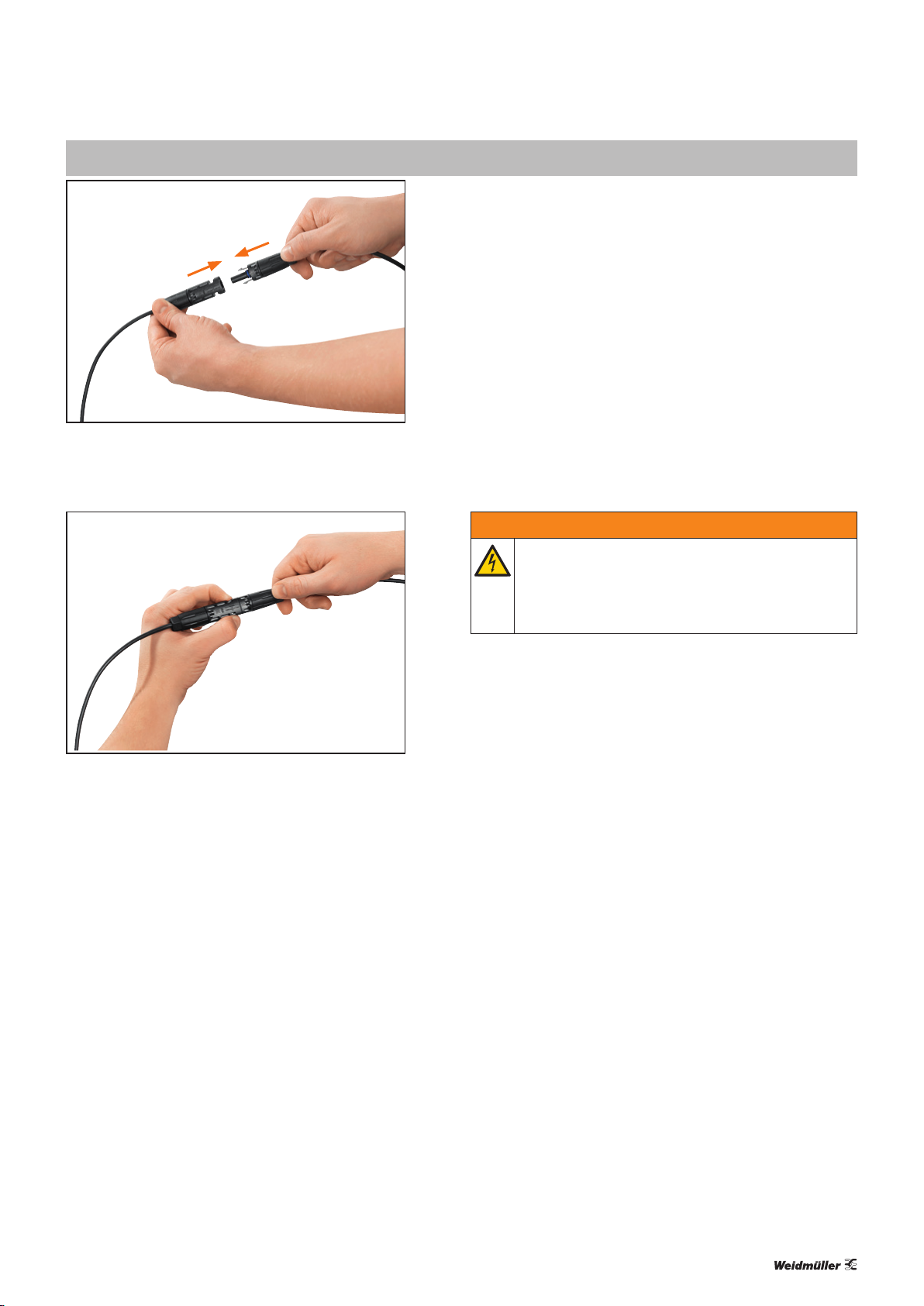
–Die elektrischen Verbindungen dürfen nicht unter Last
gesteckt und getrennt werden.
–Die Produkte dürfen nur von Elektrofachkräften installiert
werden.
–Die PV-Steckverbinder dürfen nicht in direkten Kontakt
mit Produkten oder Medien (inklusive Gase) geraten, wel-
che Benzin, Kerosin oder Weichmacher enthalten.
Sicherheitshinweise für die Montage
WARNUNG
Gefährliche Spannung!
Je nach Lichteinstrahlung kann vom Modul erzeugte
Spannung anliegen. Die elektrischen Verbindun-
gen dürfen nicht unter Last gesteckt und getrennt
werden!
Beachten Sie folgende Hinweise:
–Schützen Sie alle nicht verbundenen Steckverbinder wäh-
rend der Montage vor Schmutz und Wasser.
–Stellen Sie vor der Montage sicher, dass der O-Ring des
Steckverbinders schmutzfrei ist.
–Achten Sie während der Montage darauf, dass
WM4C-Kontakte nicht mit WM4-Gehäusen kombiniert
werden und umgekehrt.
–Stellen Sie sicher, dass spannungsführende Teile wie
Kontakte oder Kabel keinen Erdschluss erzeugen.
–Wenn Sie andere Komponenten, Hilfsmittel oder Werk-
zeuge als die von Weidmüller angegebenen bei der Mon-
tage einsetzen, kann die Einhaltung der technischen Spe-
zifikationen nicht garantiert werden.
–Die PV-Steckverbinder dürfen keinen mechanischen
Belastungen ausgesetzt werden.
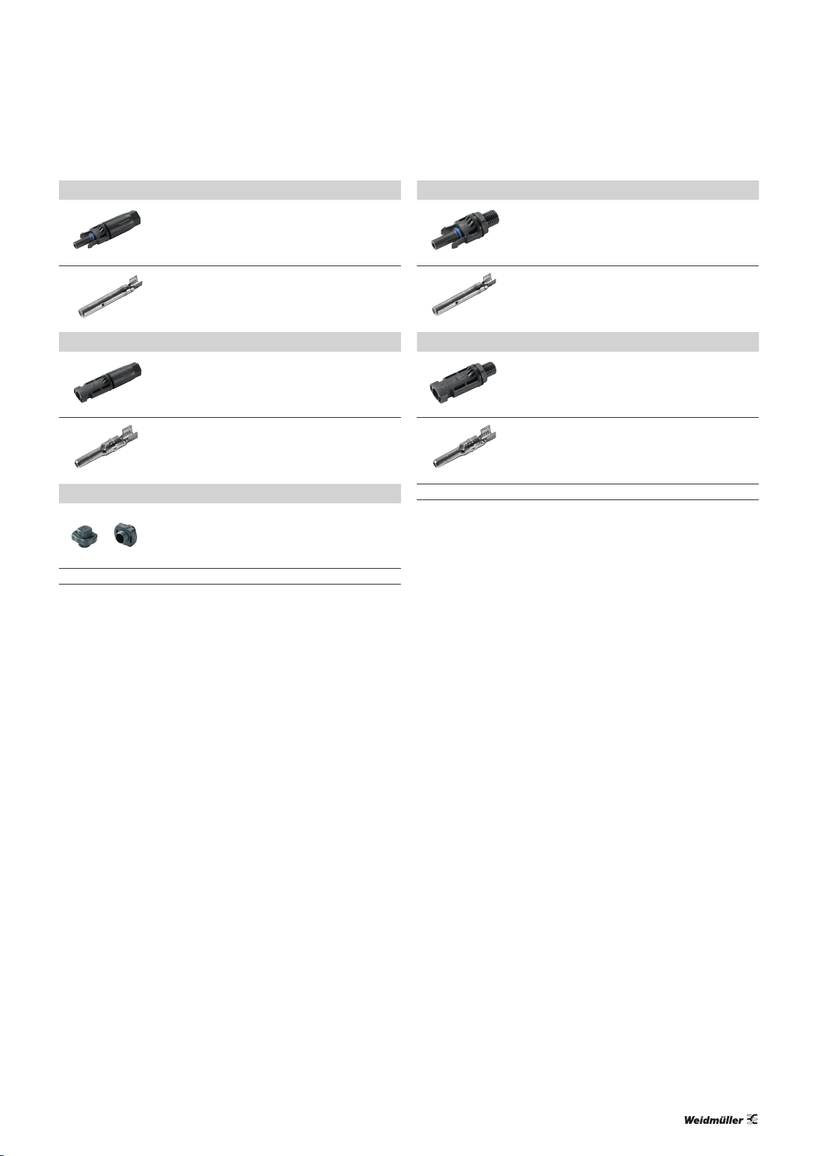
Bestimmungsgemäßer Gebrauch
Die WM4C-Steckverbinder sind für den Einsatz in Photo-
voltaikanlagen vorgesehen. Sie dürfen nur innerhalb der be-
schriebenen technischen Spezikationen verwendet werden.
WM4C-Kontakte sind nicht kompatibel mit WM4-Gehäusen
und umgekehrt.
Die Gewährleistung beschränkt sich auf die Kombination
von Weidmüller-PV-Steckverbindern.
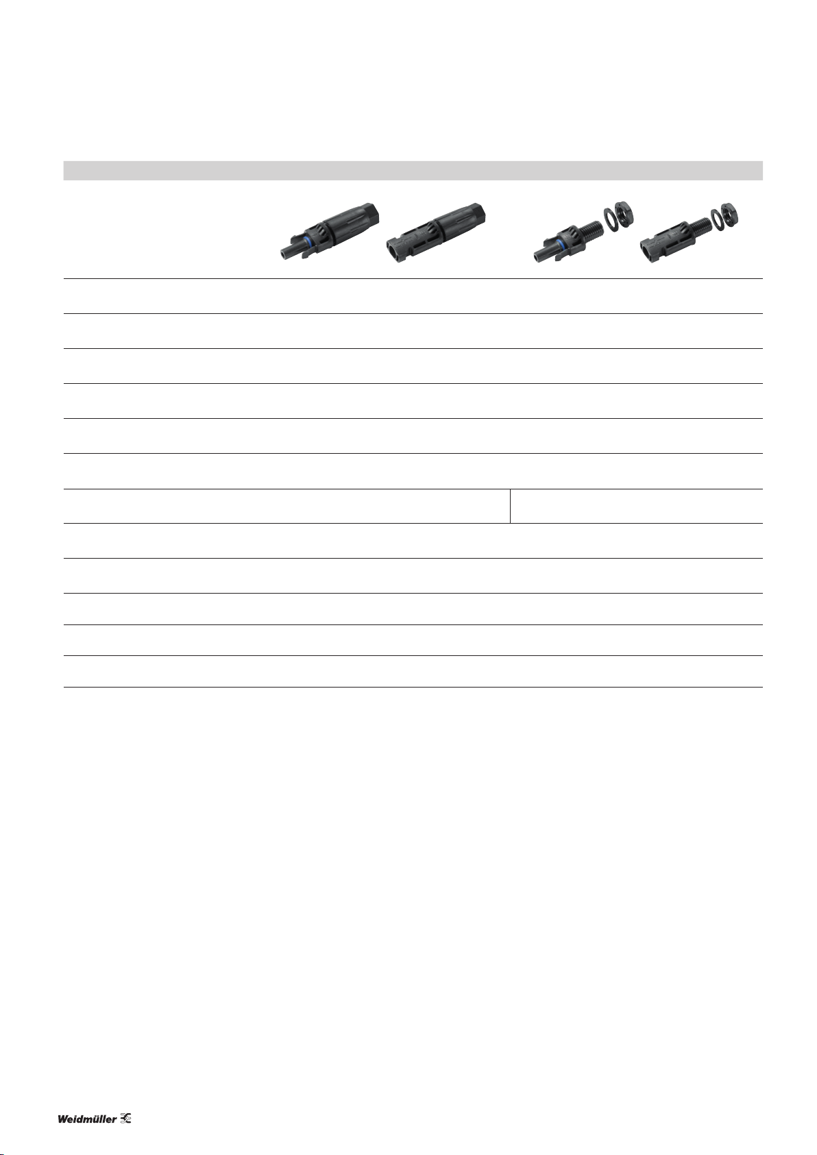
Empfohlenes Werkzeug
Werkzeug Best.-Nr.
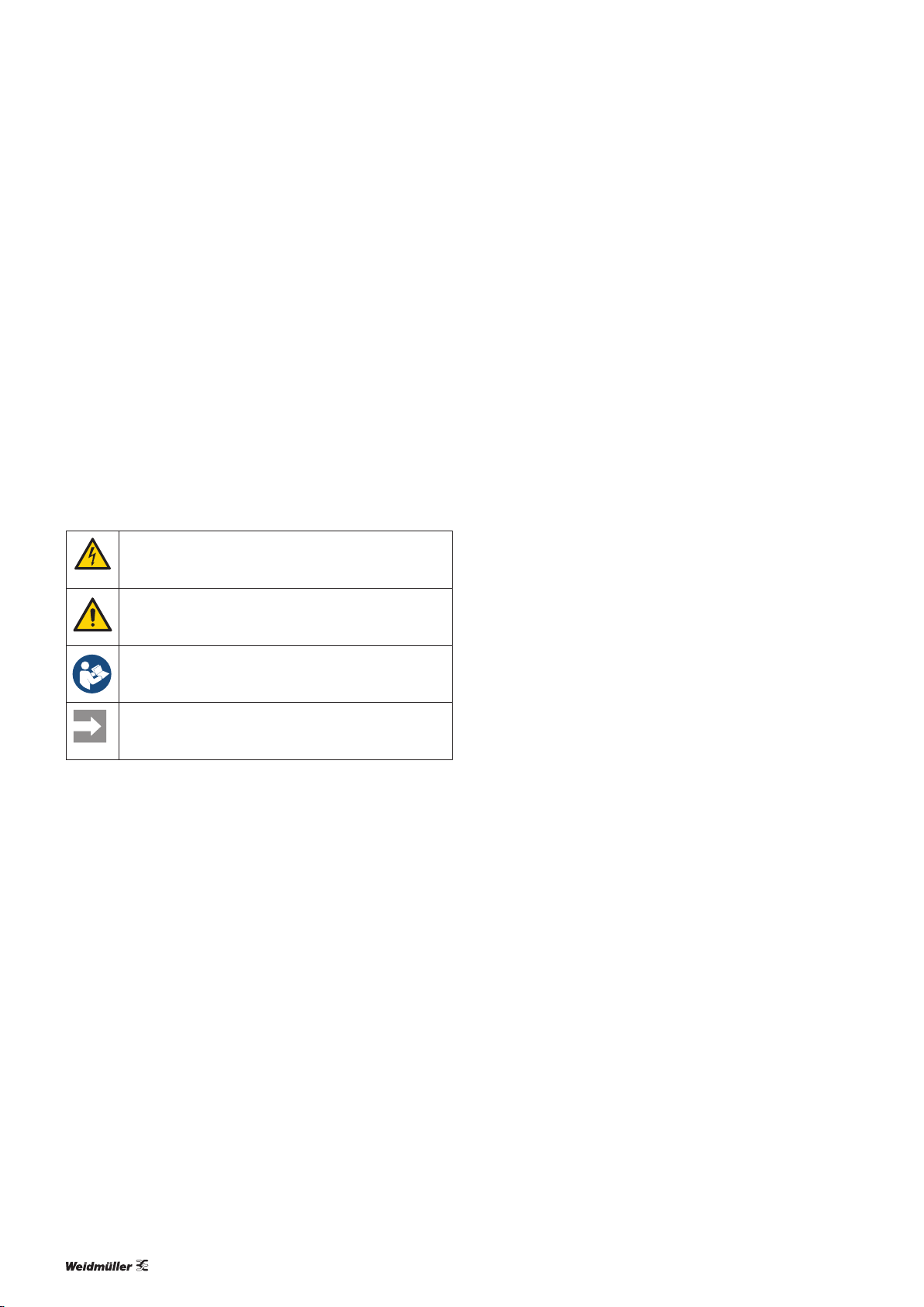
Abisolierzange multi-stripax®PV 1190490000
Crimpwerkzeug CTFPVWM4 1222870000
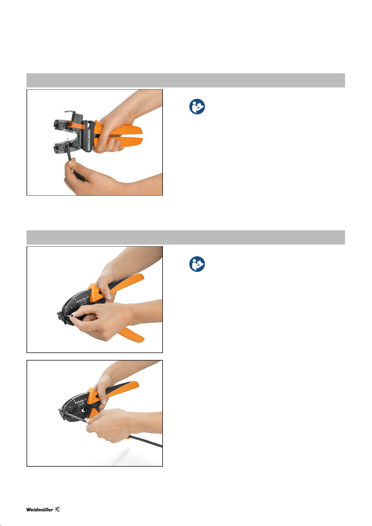
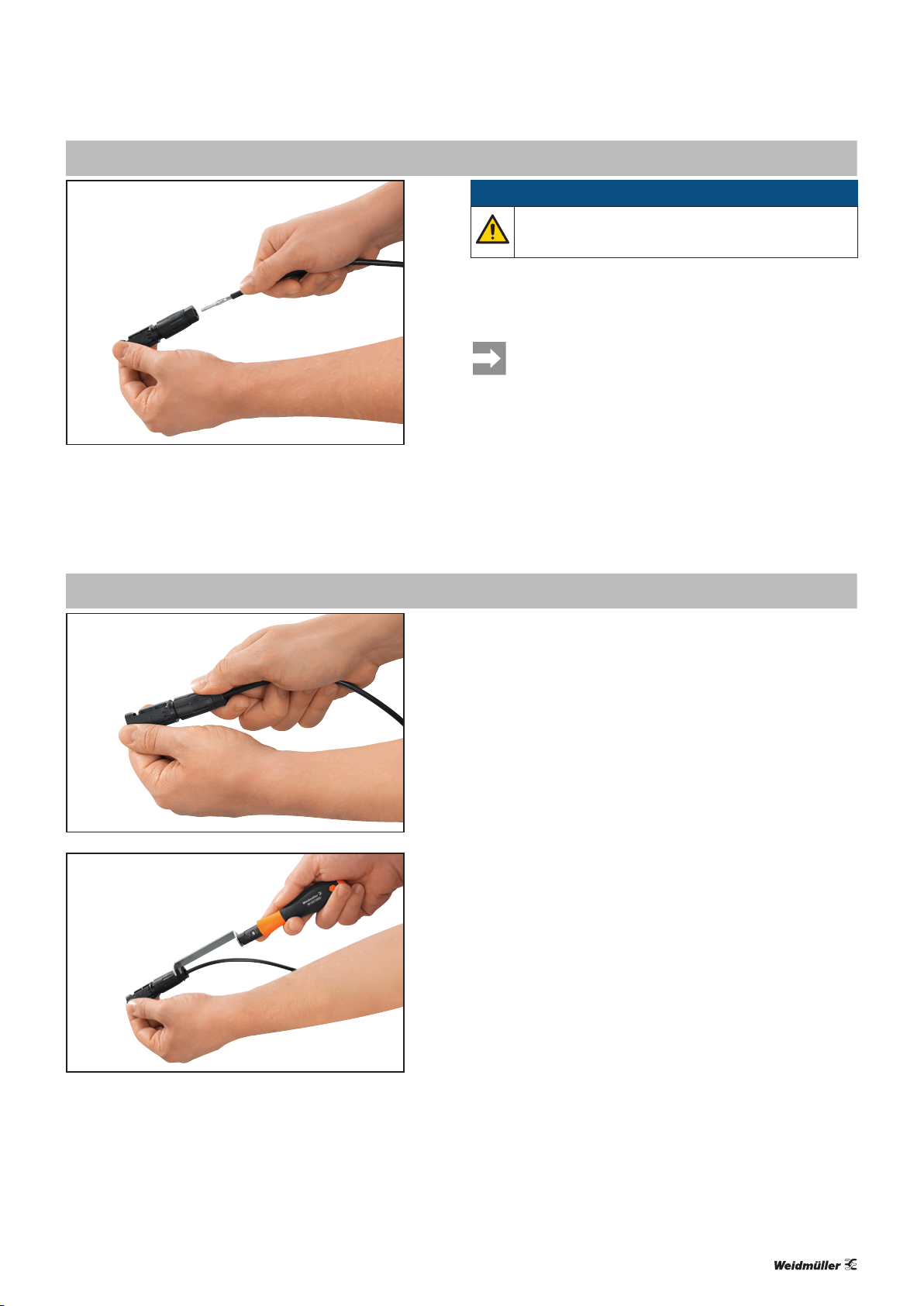
Montagewerkzeug Screwty 15 (für WM4 C)
Montagewerkzeug Screwty 18 (für BOX WM4 C)
1290830000
1254670000
Drehmomentschraubendreher DMS MANUELL 9918370000