Weil-McLain STAR-34 Owner's manual

Part Number 550-110-268/0699
Special gas vent system vent and combustionSpecial gas vent system vent and combustion
Special gas vent system vent and combustionSpecial gas vent system vent and combustion
Special gas vent system vent and combustion
air supplementair supplement
air supplementair supplement
air supplement
Venting Supplement
StaRStaR
StaRStaR
StaR-34-34
-34-34
-34
To the installer: ThisVentingSupplementmustonlybeusedbyaqualifiedinstaller/service
technician. Read these instructions completely before beginning the
installation.Failure to follow these instructions in proper order can cause
severe personal injury,death or substantial property damage.
To install a new vent system follow instructions in:
•ThisVentingSupplement.
•GV Boilers Vent/Air Intake Termination Assembly Instructions, if
using Weil-McLainVent/Air Intake Termination Kit.— OR —
•GV Water Boiler Series 2 & 3 Direct vent Through-roof or Through-
unused-chimney Venting Supplement, if using Weil-McLain
Through-Roof or Through-Unused-Chimney Termination Kit.
•StaR-34 manufacturer’s instructions supplied with vent material.
Forinstallationsabove5,500feetuse onlydirectvent(ductedcombustion
air) when sidewall venting. All of the vertical (through-roof or through-
unused-chimney)methodsinthisVentingSupplementareacceptable.Can
result in severe personal injury, death or substantial property damage if
ignored.
Flex-L International, Inc. StaR-34 AL29-4C®
Stainless Steel Special GasVent System may be
used in new installations of GV-3 through GV-6
boilers.
WW
WW
Water boiler — Series 3ater boiler — Series 3
ater boiler — Series 3ater boiler — Series 3
ater boiler — Series 3
GOLDGOLD
GOLDGOLD
GOLD GVGV
GVGV
GV
The following terms are used throughout this Venting Supplement to bring attention to the
presence of hazards of various risk levels or to important information concerning the life of
the product.
Indicates presence of hazards that will cause severe personal injury, death
orsubstantial property damage.
Indicates presence of hazards that can cause severe personal injury,death
orsubstantial property damage.
Indicatespresence of hazardsthatwillor cancause minor personal injury
orpropertydamage.
Indicates special instructions on installation, operation or maintenance
that are important but not related to personal injury or property damage.
Hazard definitions
Part Number 550-110-268/0699
2
GOLD GV Water boiler — Series 3
Combustion air supply
RefertoGV Series 3 Boiler Manual forsizingfreeareaofcombustion/ventilationairopenings.
All boilers experience some condensation in section assembly during start-up. Unlike most
conventionalboilers,condensationisminimizedintheGV Series 3 Boiler byabuilt-inmixing
system,maintainingboilerreturnwatertemperatureabove1300F,duringsteadystateoperation.
Flue gas condensate is slightly acidic. In most cases pH level is not harmful to vents or drains.
When combustion air is contaminated by vapors from products and areas, listed in Table 1
below,condensate acidic levels increase. Higher acidic levels attack many materials,including
stainless steel commonly used in high efficiency systems.
You may choose to use outside combustion air for any of the following reasons:
• Installation is in an area containing contaminants listed in Table 1 below,which will
induce acidic contamination.
• You want to reduce infiltration into your home through openings around windows
anddoors.
Special note
Topreventpotentialof severepersonalinjuryordeath,checkforareasand
products listed above before installing boiler. If found:
•remove products permanently — OR —
•provide outside combustion air
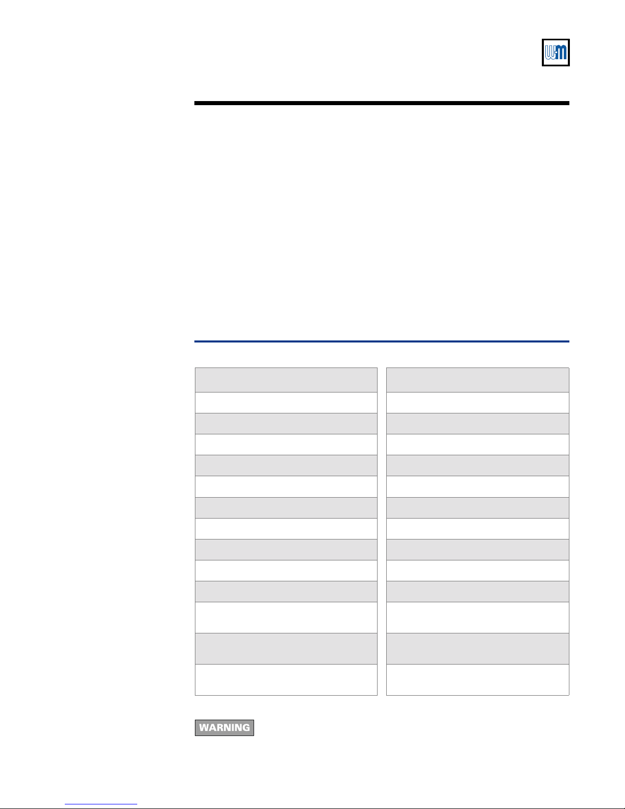
Table 1 Corrosive contaminants
Products to avoid Areas likely to have contaminants
Spray cans containing chloro/fluorocarbons Dry cleaning/laundry areas and establishments
Permanent wave solutions Swimming pools
Chlorinated waxes/cleaners Metal fabrication plants
Chlorine-based swimming pool chemicals Beauty shops
Calcium chloride used for thawing Refrigeration repair shops
Sodium chloride used for water softening Photo processing plants
Refrigerant leaks Auto body shops
Paint or varnish removers Plastic manufacturing plants
Hydrochloric acid/muriatic acid Furniture refinishing areas and establishments
Cements and glues New building construction
Antistatic fabric softeners used in clothes
dryers Remodeling areas
Chlorine-type bleaches, detergents, and clean-
ing solvents found in household laundry rooms Garages with workshops
Adhesives used to fasten building products and
other similar products
Part Number 550-110-268/0699 3
StaR-34 Venting Supplement
Vent termination
Venting method definitions
Direct vent — Uses outside combustion air with combustion
airconnectorpipingsealedatalljointsandseams.Alsoknownas
“sealedcombustion”.
Non-Direct vent — Uses inside combustion air with no
combustion air connector piping.
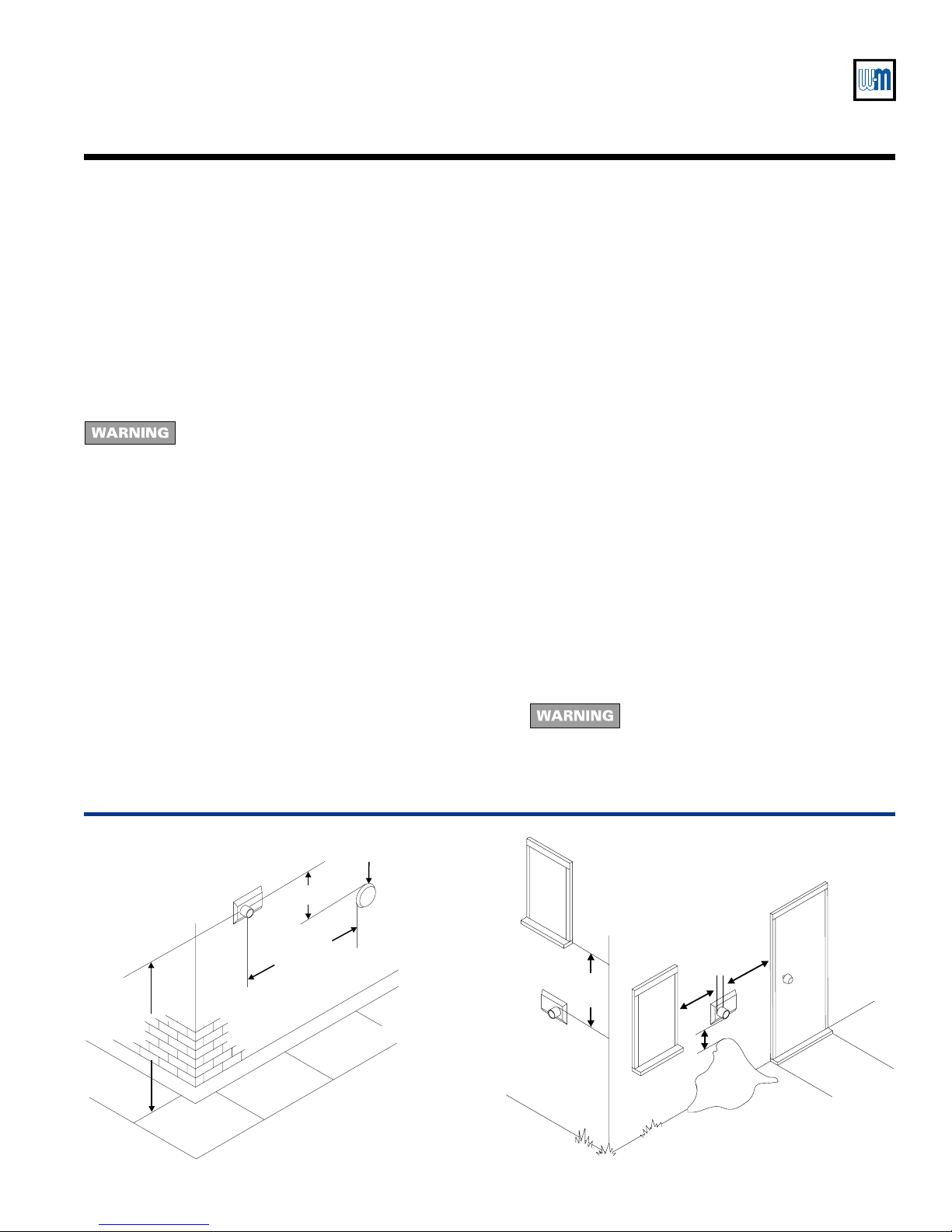
Figure 1 Vent termination locations
26807
Snow
1 foot
1 ft 1 ft
1 ft
Properly locate vent termination
Follow instructions on this page when
determiningventlocationtoavoidpossibility
ofseverepersonalinjury,deathorsubstantial
property damage.
1. When using direct vent method — Refer to separate
instructionspackedwithWeil-McLaindirectventtermination
kit and vent pipe manufacturer's instructions for additional
locations.
2. Forlocationof non-directventverticaltermination,seevent
pipemanufacturer's instructions.
3. Gaseswillformwhiteplumeinwinter.Plumecouldobstruct
windowview.
4. Prevailing winds could cause freezing of condensate and
water/ice buildup on building, plants or roof.
5. Locateorguardventtoprevent accidentalcontactbypeople
or pets.
6. Do not terminate vent in window well, stairwell, alcove,
courtyard,or other recessed areas.
7. Non-Direct vent installations only — Vent must terminate
more than 1 foot below or to side of all doors or windows.
See Figure 1.
8. Vent must terminate more than 1 foot above grade or
anticipatedsnowline.Inaddition,ventterminationmustbe
atleast7feetabovepublicwalkwayand3feetaboveanyforced
air intake within 10 feet. Stay well away from trees, shrubs,
and decorative items. Site conditions may dictate greater
clearances.See Figure 1.
9. Vent must terminate at least 4 feet horizontally, and in no
case above or below, unless a 4 foot horizontal distance is
maintained,fromelectricmeters,gasmeters,regulators,relief
valves, and other equipment.
10. Locate or guard vent to prevent condensate from damaging
exteriorfinishes.
11. Do not extend exposed vent pipe outside of building.
Condensate could freeze and block vent pipe.
12. Ventmust terminateatleast6 feetaway fromadjacentwalls.
13. Donotterminateventcloserthan5feetbelowroofoverhang.
14. Donotterminateventaboveanydoororwindow.Condensate
can freeze,causing ice formations.
15. Do not useexisting chimneyasraceway if anotherappliance
or fireplace is vented into or through chimney.
16. Do not connect:
•Any other appliance to vent pipe.
•Multiple boilers to a common vent pipe.
17. Do not wrap or insulate vent pipe and fittings.
18. Canadian installations — See CAN/CGA B149.1 or B149.2
InstallationCode.
19. A gas vent extending through an exterior
wallshallnotterminateadjacenttothewall
orbelowbuildingextensionssuchaseaves,
parapets, balconies or decks. Failure to
comply could result in severe personal
injury, death or substantial property
damage.
26808
Forced
air intake
Public Walkway
3 feet
If within 10 feet
7 feet

Part Number 550-110-268/0699
4
GOLD GV Water boiler — Series 3
Installation
Pre-installation planning
1. Follow national, state,local or provincial codes or
regulationswhenventing GV boiler.
2. Chooseventmethodfromthoseshownon page5.
3. Selectventrun components fromTable 2. Table 3
states maximum vent run lengths and number of
elbows.DonotexceeddatainTable 3.Longervent
runswillslightlyreduceboileroutput.SeeFigure 2.
4. If installing with direct vent method, use same
maximumrun lengthand number of elbowsfrom
Description Flex-L International, Inc.
Part Number (Note 1)
GV starter tee --
GV termination coupling SRAWGVT
45
o
elbow SRE4503
90
o
elbow SRE9003
6" pipe SR06P03
1' pipe SR12P03
2' pipe SR24P03
3' pipe SR36P03
5' pipe SR60P03
Joiner band SRJB-14
Weil-McLain Vent/Air Intake Termination Kit 382-200-430 (Note 2)
Weil-McLain Through-Roof or Through-Unused-Chimney Termination Kit 382-200-435 (Note 2)
Notes
1. Flex-L International, Inc. part number. Parts available through Flex-L International, Inc.
2. Weil-McLain part number. Parts available through Weil-McLain distributor.
Table 2
Parts list
step 2.Vent and combustion air connector piping
configurationsmustmatch.Usesuitable3"material
for combustion air connector piping,such as:
•Dryer vent
•Galvanizedsteel
•PVC (3" I.D.)
5. Refer to vent termination WARNING, item 19 on
page 3.
Table 3
Vent and combustion air connector piping
lengths and number of elbows
Figure 2 Boiler output
Maximum vent
length (feet) Total number of elbows
0 2 3 4 5 6 7 8
GV-3 through GV-5 100 80 70 60 50 40 30 20
GV-6 80 60 50 40 30 20 10 --
GV-6
GV-5
GV-4
GV-3
020 40 60 80 100
Total equivalent length (feet) of vent
(from boiler to vent termination)
% Output
95
96
98
97
99
100
26800
Part Number 550-110-268/0699 5
StaR-34 Venting Supplement
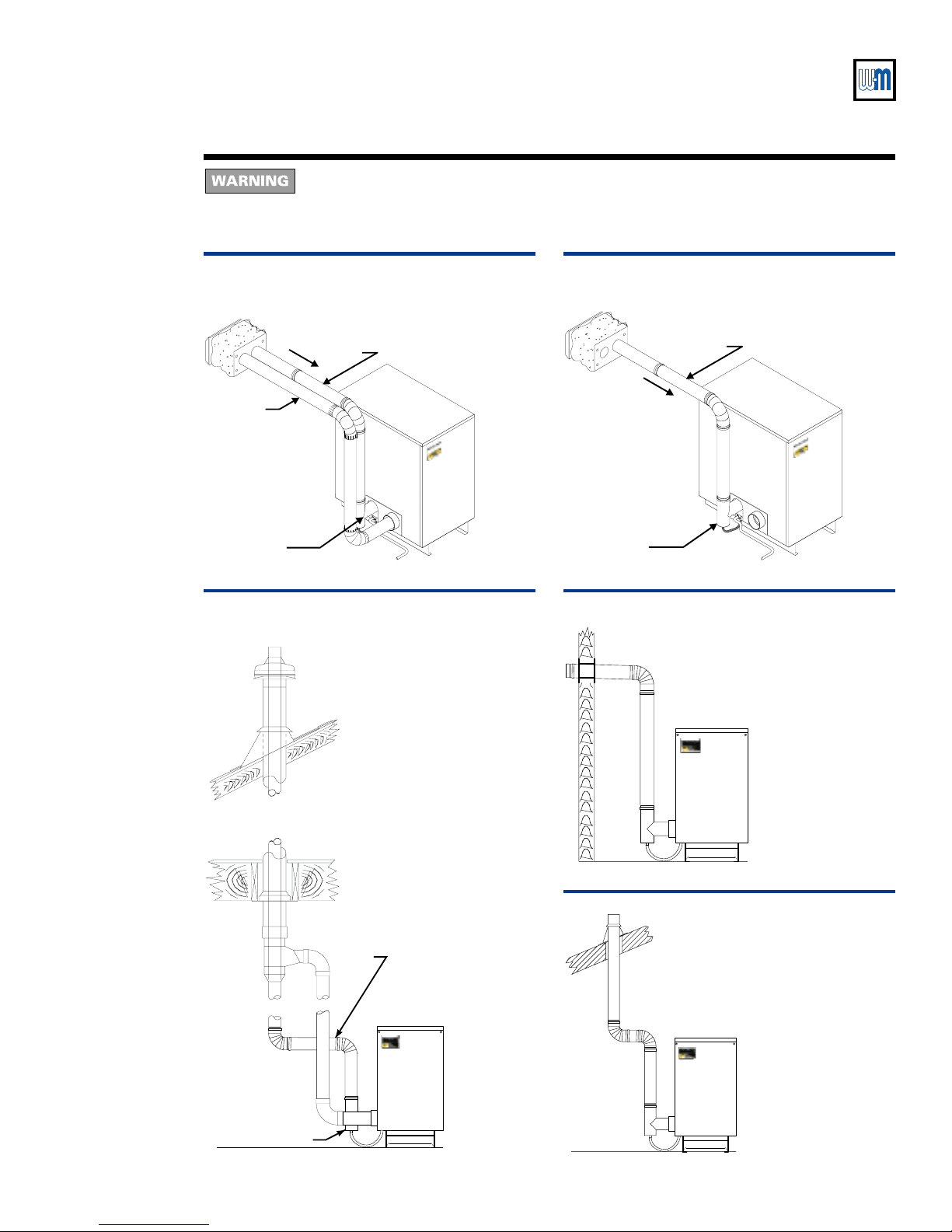
26801
Air pipe
Vent pipe
StaR-34
vent starter tee
Slope
Slope vent pipe downward, toward
boiler, minimum ¼” per foot.
Figure 3 GV direct vent through sidewall
(using Weil-McLain Vent/Air Intake
Termination Kit)
Figure 5 GV direct vent (using Weil-McLain
Through-Roof or Through-Unused-
Chimney Termination Kit)
26803
Slope vent pipe
downward, toward
boiler, minimum
¼” per foot.
StaR-34
vent starter tee
Select
vent
method
Figure 7 GV non-direct vent through roof
26805
Slope vent pipe
downward,
toward boiler,
minimum ¼”
per foot.
StaR-34
vent starter tee
26804
Slope vent pipe
downward, toward
boiler, minimum
¼” per foot.
StaR-34
vent starter tee
Figure 6 GV non-direct vent through sidewall
(using termination coupling)
(See WARNING above.)
26802
Vent pipe
StaR-34
vent starter tee
Slope
Slope vent
pipe
downward,
toward boiler,
minimum ¼”
per foot.
Figure 4 GV non-direct vent through sidewall
(using Weil-McLain Vent/Air Intake
Termination Kit) (See WARNING above.)
For altitudes more than 5,500 feet above sea level — Do not use non-direct vent through
sidewall methods as shown in Figures 4 and 6below.Can cause severe personal injury, death
or substantial property damage if ignored.

Part Number 550-110-268/0699
6
GOLD GV Water boiler — Series 3
Installation — assembly
Connect vent starter
tee to boiler Follow the instructions in the GV Series 3 Boiler Manual section IIII
IIII
IIbb
bb
bto connect the vent
starter tee to the boiler.
Construct vent and
optional
combustion air run
Followventpipemanufacturer'sinstructionsforsealingthevent.Ventand
combustion air connector piping must be sealed gas-tight to prevent
possibilityoffluegasspillageandcarbonmonoxideemissions,resultingin
severe personal injury or death.
1. Follow StaR-34 manufacturer's instructions to construct vent run and for methods of
supporting vent runs.
•Clean joints before sealing. See vent pipe manufacturer's instructions to clean joints.
•Use their specified sealant (maximum 250 0F flue temperature).Do not use screws.
•Do not mix types or manufacturers of vent materials.
•Maintain minimum one-inch clearance from combustible materials to vent pipe; 0"
clearance fornoncombustiblematerials.
•Install vent pipe with seams on top of vent runs.
•If needed, male end of vent pipe may be cut to provide correct length.See vent pipe
manufacturer'sinstructions foruse.
2. If installing with direct vent method, use instructions provided with Weil-McLain
termination kit. See Figures 3, 4 or 5 on page 5.
Venting through sidewall
Connect vent run to
termination 1. If using Weil-McLainVent/Air Intake Termination Kit, see instructions provided in that
kit.Applies to direct (Figure 3,page 5) or non-direct vent (Figure 4, page 5) method.
2. If using non-direct method with termination coupling only, seeFigures 8 and 9.
•If passingthrough noncombustiblewall,providehole diameterlarge enoughtoinsert
the pipe through.Sleeve and spacers are not required.
3. Maintain minimum one-inch clearance from combustible materials to vent pipe; 0"
clearance fornoncombustiblematerials.
4. Refer to vent termination WARNING,item 19 on page 3.
1. Direct vent method — follow instructions supplied in Weil-McLain Through-Roof or
Through-Unused-Chimney Termination Kit to assemble termination.
2. Non-Direct vent method (only through the roof, not through chimney):
•Vent pipe must extend through roof flashing,jacket or thimble.See Figure 10.
•Vent may pass through floor,inside wall or concealed space when installed according
to vent pipe manufacturer's instructions.
3. Maintain minimum one-inch clearance from combustible materials to vent pipe.
Venting through existing chimney or roof
Part Number 550-110-268/0699 7
StaR-34 Venting Supplement
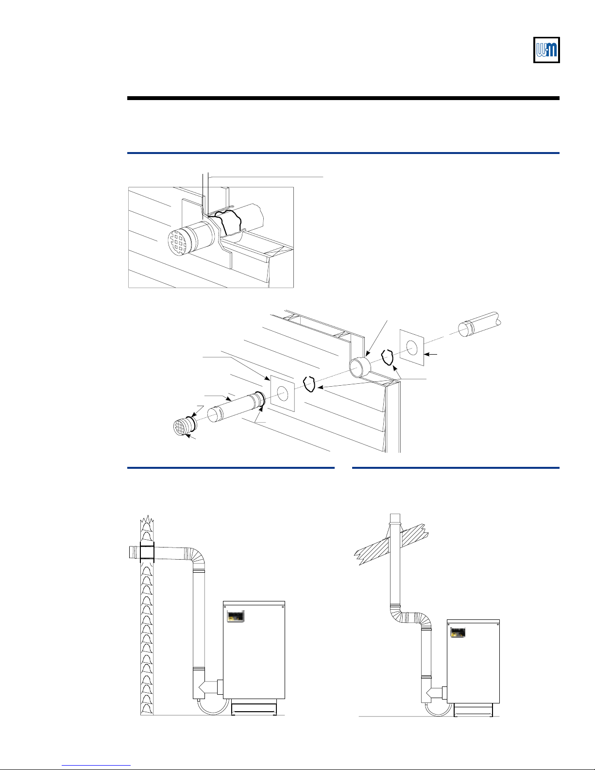
Figure 8 Sidewall termination installation (non-direct venting)
26809
¼" to ¾" between stop
on termination and
metal plate
4" galvanized sleeve
(through 4 " hole for
wall)
¹⁄₈
combustible Pipe section
Metal plate
Spacers (2)
(to support and
center vent in
sleeve)
Metal plate
Pipe section
Termination coupling
Sealant
Sealant
26804b
StaR-34
vent starter tee
Figure 9 Non-direct vent through sidewall (using
termination coupling)
Follow StaR-34 manufacturer’s instructions
for proper installation of vent runs, including
slope and support.
Figure 10 Non-Direct vent through roof
Follow StaR-34 manufacturer’s instructions
for proper installation of vent runs, including
slope and support.
26805b
StaR-34
vent starter tee
Part Number 550-110-268/0699
8
GOLD GV Water boiler — Series 3
Weil-McLain
500 Blaine Street
Michigan City, IN 46360-2388
http://www.weil-mclain.com
Installation — assembly continued
Finish the vent
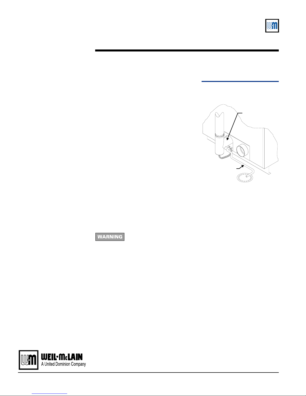
installation Figure 11
Installation of condensate tubing
Sealantrecommendedbyventpipemanufacturermustbeusedasindicated
in their instructions. Vent and combustion air connector piping must be
sealed gas-tight to prevent possibility of flue gas spillage and carbon
monoxide emissions,resulting in severe personal injury or death.
1. See Figure 11 to install condensate tubing
(providedbyothers).Usecondensatepump
iffloordrainishigherthancondensatedrain
on boiler.
If required:
• use a low-profile pump — OR —
• setboileronfoundation(seeGV Series
3 Boiler Manual) to allow gravity flow
to pump.
2. Size pump in gal/hr. (boiler model):
• 0.78(GV-3)
• 1.17(GV-4)
• 1.56(GV-5)
• 1.95(GV-6)
Refertopumpmanufacturer'sinstructions.
Drain to a non-freezing area.
Installing condensate tubing
If vent pipe or combustion air pipe must be reassembled
Whenventpipeorcombustionairpipeisdisconnectedforanyreason,itmustbereassembled
andresealedaccordingtothisVentingSupplement,thedirectventterminationkitinstructions
and the vent pipe manufacturer's instructions.
26806
StaR-34
vent starter tee
5/8" O.D. tubing,
provided by
others
Vent
Table of contents


