Viking Range RDIPR101R User manual

1
VIKING RANGE CORPORATION D3 Downdraft Ventilators
WARNING
READ AND SAVE THESE INSTRUCTIONS
WARNING
TO REDUCE THE RISK OF FIRE, ELECTRIC SHOCK, OR IN-
JURY TO PERSONS, OBSERVE THE FOLLOWING:
1. Use this unit only in the manner intended by the manufacturer.
If you have questions, contact the manufacturer at the address
or telephone number in the warranty.
2. Before servicing or cleaning unit, switch power off at service
panel and lock the service disconnecting means to prevent
power from being switched on accidentally. When the service
disconnecting means cannot be locked, securely fasten a
prominent warning device, such as a tag, to the service panel.
3. Installation work and electrical wiring must be done by a
qualified person(s) in accordance with all applicable codes
and standards, including fire-rated construction codes and
standards.
4. Sufficient air is needed for proper combustion and exhausting
of gases through the flue (chimney) of fuel burning equip-
ment to prevent backdrafting. Follow the heating equipment
manufacturer’s guideline and safety standards such as those
published by the National Fire Protection Association (NFPA),
and the American Society for Heating, Refrigeration and Air
ConditioningEngineers (ASHRAE),andthelocalcodeauthori-
ties.
5. When cutting or drilling into wall or ceiling, do not damage
electrical wiring and other hidden utilities.
6. Ducted fans must always be vented to the outdoors.
7. To reduce the risk of fire, use only metal ductwork.
8. Do not install this product with the activating switch directly
behind a burner or element. Minimum distance between the
switch and the edge of the cook top or range top should be 4
inches.
9. Loose-fitting or hanging clothing should never be worn when
operating this appliance. They may be ignited by burners/
elements on cooktop.
10. Children should not be left alone or unattended in the area
where this appliance is in use.
11. This unit must be grounded.
TO REDUCE THE RISK OF A RANGE TOP GREASE FIRE:
a) Never leave surface units unattended at high settings.
Boilovers cause smoking and greasy spillovers that may
ignite. Heat oils slowly on low or medium settings.
b) Always turn hood ON when cooking at high heat or when
cooking flaming foods.
c) Clean ventilating fans frequently. Grease should not be
allowed to accumulate on fan or filter.
d) Use proper pan size. Always use cookware appropriate
for the size of the surface element.
TO REDUCE THE RISK OF INJURY TO PERSONS IN THE
EVENT OF A RANGE TOP GREASE FIRE, OBSERVE THE
FOLLOWINGa:
1. SMOTHER FLAMES with a close-fitting lid, cookie sheet,
or metal tray, then turn off the burner. BE CAREFUL TO
PREVENT BURNS. If the flames do not go out immediately,
EVACUATE AND CALL THE FIRE DEPARTMENT.
2. NEVER PICK UP A FLAMING PAN - You may be
burned.
3. DO NOT USE WATER, including wet dishcloths or towels
- a violent steam explosion will result.
4. Use an extinguisher ONLY if:
A. You know you have a Class ABC extinguisher, and you
already know how to operate it.
B. The fire is small and contained in the area where it
started.
C. The fire department is being called.
D. You can fight the fire with your back to an exit.
aBased on “Kitchen Firesafety Tips” published by NFPA.
CAUTION
1. For general ventilating use only.Do not use to exhaust hazard-
ous or explosive materials and vapors.
2. To avoid motor bearing damage and noisy and/or unbalanced
impellers, keep drywall spray, construction dust, etc. off power
unit.
3. Clean filters and grease-laden surfaces frequently.
4. Do not repair or replace any part of this appliance unless
specifically recommended in this manual. All other servicing
should be done by a qualified technician.
5. Please read specification label on product for further informa-
tion and requirements.
MODEL WIDTH BLOWER (purchase separately)
RDIPR101R 30" w/ remote control VIDV500 Interior or VEDV900 Exterior
RDIPR161R 36" w/ remote control VIDV500 Interior or VEDV900 Exterior
RDIPR151R 45" w/ remote control VIDV500 Interior, VEDV900 Exterior, or VEDV1200 Exterior
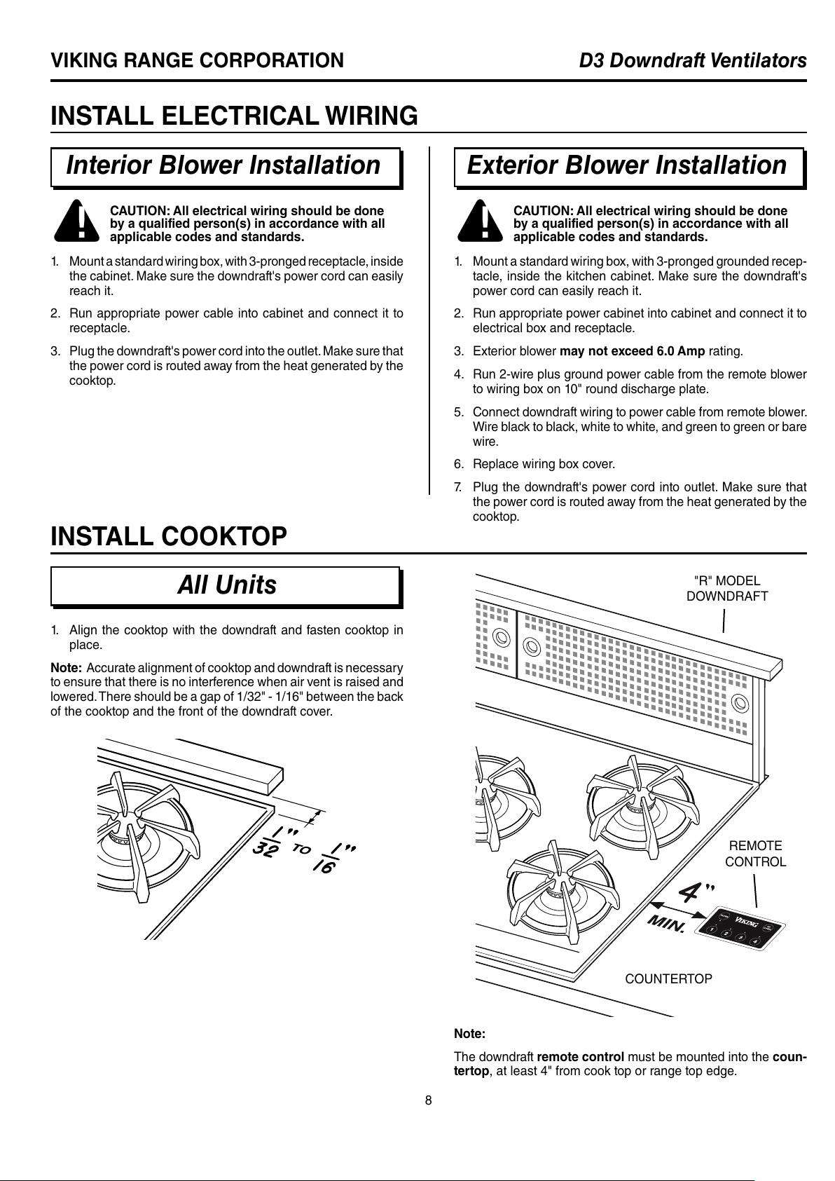
WARNING - To reduce the risk of burns or ignition of clothing by reaching across burners, the downdraft remote control MUST
be mounted in the countertop - at least 4" from the burners. See "INSTALL COOKTOP" section on page 8.
!
INSTALLER:
Save this manual for Electrical
Inspector and Homeowner to use.
HOMEOWNER:
Use and Care Information on Page 11.
!
INTENDED FOR DOMESTIC COOKING ONLY
!
All manuals and user guides at all-guides.com
all-guides.com

2
D3 Downdraft VentilatorsVIKING RANGE CORPORATION
AIR
VENT
COUNTER
TOP
BLOWER
BOX
CHIMNEY TOP
COOK TOP
GEAR
MOTOR
COVER
TYPICAL INSTALLATION
120 VAC
GROUNDED
OUTLET
Thisdowndraft blowersystem is
designed to be used to exhaust
airborne contaminants when
cooking with a variety of gas
or electric cooktops. It can be
mounted in island, peninsula,
or conventional wall locations.
This unit can be easily installed
following these basic steps:
• Cut out the countertop
opening.
• Mount the unit in the cabi-
net.
• Install the Model VIDV500
Interior Blower
• Connect the ductwork and
electrical.
• Install the cooktop.
Note: the high level of air flow
of this appliance may effect the
gas flame on some types of gas
cooktops.This is NORMAL and
will cause no harm, but can be
corrected bylowering the speed
of the blower.
PLANNING
Interior Blower Installation Exterior Blower Installation
Note: the high level of air flow of this appliance may effect the
gas flame on some types of gas cooktops. This is NORMAL and
will cause no harm, but can be corrected by lowering the speed
of the blower.
TYPICAL INSTALLATION
120 VAC
GROUNDED
OUTLET
AIR
VENT
GEARMOTOR
COVER
This downdraft blower system
is designed to be used to ex-
haust airborne contaminants
when cooking with a variety
of gas or electric cooktops.
It can be mounted in island,
peninsula,orconventionalwall
locations.
Thisunitcanbe easilyinstalled
following these basic steps:
• Cut out the countertop
opening.
• Mount the unit in the
cabinet.
• Install 10" round dis-
charge plate
• Install Model VEDV900 or
VEDV1200 (DIPR151RSS
only) External Blower
• Connect the ductwork
and electrical.
• Install the cooktop.
COOK TOP
COUNTER TOP CHIMNEY TOP
10" ROUND
DISCHARGE
PLATE
10" ROUND DUCTWORK
ELECTRICAL
SPECIFICATIONS
120 VAC • 60 Hz • 4.0 A
TAKE MEASUREMENTS
All Units
1. Refer to the cooktop installation instructions for dimensions
of cooktop, countertop cut-out, and cabinet requirements.
The Model RDIPR101RSS will fit in most 30" wide cabinets,
the Model RDIPR161RSS will fit in most 36" wide cabinets,
and the Model RDIPR151RSS will fit most 45" wide cabinets.
However, it is recommended that oversized cabinets be used
for easier installation.
2. Cooktop depth can vary greatly from one to another.This may
cause the fit of these two appliances to be rather tight.
Pay special attention to the areas of potential interference high-
lighted above. A countertop with (A) a raised lip and/or (B) a
backsplash may not allow enough flat countertop for a proper
installation. Note that 2" of flat countertop is required behind
cooktop and that 1-3/4" is necessary between the back edge of
the cooktop and the inside of cabinet back.
ELECTRICAL
SPECIFICATIONS
120 VAC • 60 Hz • 6.0 A (max.)
3-1/4" X 10"
DUCT CONNECTOR
All manuals and user guides at all-guides.com

3
VIKING RANGE CORPORATION D3 Downdraft Ventilators
1. The interior down-
draft blower system is
designed for use with
3-1/4" x 10" ductwork
(can be transitioned
to 6" round). Three
different discharge
directions are avail-
able with side-to-
side adjustment for
accurate alignment of
ductwork.
2. For best performance:
Choose the ducting
option which allows
the shortest length
of ductwork and a
RIGHT
DISCHARGE
DOWN DISCHARGE
LEFT
DISCHARGE
PLAN THE DUCTWORK
Interior Blower Installation Exterior Blower Installation
10" ROUND
DISCHARGE
PLATE
1. The exterior downdraft
blower system is designed
for use with 10" round duct-
work.
2. For best performance:
Plan ducting which has the
shortest length of ductwork
and a minimum number of
elbows. Check location of
floor joists, wall studs, elec-
trical wiring or plumbing for
possible interference.
EQUALS 6 FT. OF
STRAIGHT DUCT
10" ROUND
ELBOW
EQUALS 6 FT. OF
STRAIGHT DUCT
6" ROUND
ELBOW
EQUALS 8 FT. OF
STRAIGHT DUCT
3. The system will operate most efficiently when the ductwork
does not exceed 40 feet of equivalent duct. The chart, above,
shows equivalent feet of elbows and transitions.The number
of feet of straight duct plus the equivalent feet of transitions
and/or elbows to be used should equal 40 feet or less.
NOTE: The equivalent feet of various roof and wall caps has
been taken into consideration. Do not include them in this
calculation.
3-1/4" X 10" TO 6" RD.
TRANSITION 3-1/4" X 10"
90OELBOW
minimum number of elbows and transitions. Check location
of floor joists, wall studs, electrical wiring or plumbing for
possible interference.
3. The system will operate most efficiently when the ductwork
does not exceed 40 feet of equivalent duct. The illustration,
above,showsequivalentfeetof a 10" round elbow.Thenumber
of feet of straight duct plus the equivalent feet of elbows to be
used should equal 40 feet or less.
NOTE: The equivalent feet of various roof and wall caps has
been taken into consideration. Do not include them in this
calculation.
Interior Blower Installation Exterior Blower Installation
TAKE MEASUREMENTS (CONTINUED)
EQUALS
2 FT. OF
STRAIGHT DUCT
SIDE VIEW
OF DOWNDRAFT
WITH
VIDV500
INTERIOR
BLOWER
SIDE VIEW
OF DOWNDRAFT
WITH
10" ROUND ELBOW
(for connection
to VEDV900
or VEDV1200
(DIPR150RSS only))
VIDV500
INTERIOR
BLOWER
All manuals and user guides at all-guides.com

4
D3 Downdraft VentilatorsVIKING RANGE CORPORATION
PLAN THE CABINET CUTOUTS
Interior Blower Installation Exterior Blower Installation
CENTER LINE
OF COUNTER
CUTOUT
CENTER LINE
OF DUCT CUTOUT
1" to 8"
5½"
10¼" x 3½"
CUTOUT
(TYP.)
CENTER LINE
OF COUNTER
CUTOUT
CENTER
LINES OF
DUCT
CUTOUT
16
3
/
8
"
5½"
10¼" x 3½"
CUTOUT
(TYP.)
CENTER LINE
OF COUNTER
CUTOUT
CENTER LINES
OF DUCT
CUTOUT
19¾"
10" ROUND
CUTOUT
(TYP.)
10¼"
CENTER LINE
OF COUNTER
CUTOUT
CENTER
LINE
OF DUCT
CUTOUT
2¾"
10¼"
10" ROUND
DIA. CUTOUT
(TYP.)
3½"
6¼"
CENTER LINE
OF DUCT CUTOUT
(can be located within this area)
CENTER LINE
OF COUNTER
CUTOUT
19¾"
10¼"
10" ROUND
CUTOUT
(TYP.)
CENTER
LINES OF
DUCT
CUTOUT
CENTER LINE
OF COUNTER
CUTOUT
CENTER
LINES OF
DUCT CUTOUT
24
1
/
8
"
10¼" x 3½"
CUTOUT
(TYP.)
5½"
BOTTOM
DISCHARGE
RIGHT SIDE
DISCHARGE
LEFT SIDE
DISCHARGE
BOTTOM
DISCHARGE
RIGHT SIDE
DISCHARGE
LEFT SIDE
DISCHARGE
!
CAUTION:
BEFORE CUTTING HOLE IN
CABINET FOR DUCTWORK,
check for interference with floor
joists, wall studs, electrical wir-
ing, or plumbing.
All manuals and user guides at all-guides.com

5
VIKING RANGE CORPORATION D3 Downdraft Ventilators
PLAN THE WIRING
Interior Blower Installation Exterior Blower Installation
PREPARE THE DOWNDRAFT
Interior Blower Installation
The downdraft is shipped without a blower. Purchase a Model
VIDV500 Interior Blower and mount it to the downdraft as follows:
1. Place the downdraft on its back on a table of flat work surface.
2. Remove the 4 nuts and 2 clamp channels.
3. Remove 2 screws and the gear motor cover.
4. Carefully position the blower under the bottom flange of the
downdraft with the 3¼" x 10" discharge pointed in the desired
direction.
5. Connect motor plug.
6. Replace the gear motor cover and 2 sheet metal screws.
7. Replace the 2 clamp channels and start the 4 nuts, do not
tighten.
8. Slide blower left of right to desired position. Use cover plate
(supplied) to close up any open space.
9. Tighten 4 nuts to secure top of blower.Use additional screws
(supplied) through bottom flange to secure bottom in blower.
NUTS
BLOWER
COVER
PLATE
CLAMP
CHANNELS
SCREWS
GEARMOTOR
COVER
MOTOR
PLUG
3¼" X 10"
DISCHARGE
ADDITIONAL
SCREWS
BOTTOM
FLANGE
PLEASENOTE:Externalblowersmustbehard-wiredusinglocally-
supplied wire and connected to the downdraft plug (included).
1. The Interior Downdraft Blower system draws 4 AMPS and
requires a 120 VAC, 60 Hz circuit.
2. The downdraft has a 2 ft. long power cord with a 3-pronged
plug.Plan to provide a grounded outlet in a location which will
allow the unit’s power cord to reach.
IMPORTANT - LOCATION OF ELECTRICAL OUTLET:
If Model RDIPR101RSS is being installed in a 30" wide
cabinet...
or Model RDIPR161RSS is being installed in a 36" wide
cabinet...
or Model RDIPR151RSS is being installed in a 45" wide
cabinet...
...the outlet cannot be located on the back wall
of cabinet.
In these cases, the width of the downdraft covers nearly the
entire width of the back wall of the cabinet. So you must
either:
• mounttheelectricalboxtoasidewallorcabinetfloor
- at least 12 inches from the back wall.
• mount the electrical boxto a wall stud behind the
cabinet - where it will not be covered by the downdraft
Thenprovide a clearance hole in the backwall of the
cabinet.
1. The Exterior Downdraft Blower system draws 6 AMPS and
requires a 120 VAC, 60 Hz circuit.
2. The downdraft has a 2 ft. long power cord with a 3-pronged
plug.Plan to provide a grounded outlet in a location which will
allow the unit’s power cord to reach.
IMPORTANT - LOCATION OF ELECTRICAL OUTLET:
If Model RDIPR101RSS is being installed in a 30" wide
cabinet...
or Model RDIPR161RSS is being installed in a 36" wide
cabinet...
or Model RDIPR151RSS is being installed in a 45" wide
cabinet...
...the outlet cannot be located on the back wall
of cabinet.
In these cases, the width of the downdraft covers nearly the
entire width of the back wall of the cabinet. So you must
either:
• mounttheelectricalboxtoasidewallorcabinetfloor
- at least 12 inches from the back wall.
• mount the electrical boxto a wall stud behind the
cabinet - where it will not be covered by the downdraft
Thenprovide a clearance hole in the backwall of the
cabinet.
All manuals and user guides at all-guides.com

6
D3 Downdraft VentilatorsVIKING RANGE CORPORATION
PREPARE THE DOWNDRAFT
Exterior Blower Installation
The downdraft is shipped without a blower. Purchase a Model
VEDV900 Exterior Blower and mount the 10" discharge plate
to the downdraft as follows:
1. Place the downdraft on its back on a table of flat work surface.
2. Remove the 4 nuts and 2 clamp channels.
3. Remove 2 screws and the gear motor cover.
4. Carefully position the10" discharge plate under the bottom
flange of the downdraft.
5. Connect motor plug.
6. Replace the gear motor cover and 2 sheet metal screws.
7. Replace the 2 clamp channels and start the 4 nuts, do not
tighten.
8. Slide blower left of right to desired position. Use cover plate
(supplied) to close up any open space.
9. Tighten 4 nuts to secure top of blower.Use additional screws
(supplied)throughbottomflangetosecurebottomofdischarge
plate.
NUTS
COVER
PLATE
CLAMP
CHANNELS
SCREWS
GEARMOTOR
COVER
MOTOR
PLUG
10" ROUND
DISCHARGE
PLATE
ADDITIONAL
SCREWS
BOTTOM
FLANGE
CUT COUNTERTOP OPENING
All Units 1. Measure and cut the countertop opening for your width of
cooktop and downdraft.
Cooktop Width & Model 30" RDECU206 36" RDECU266 45" RDECU256
30" RDGSU200 36" RDGSU260
For use with Downdraft Models RDIPR101RSS RDIPR161RSS RDIPR151RSS
Cutout Dimensions A 29-1/8" 34-7/8" 42-7/8"
B 20-5/8" 20-5/8" 20-5/8"
C 27" 33" 42"
D 2-1/4" 2-1/4" 2-1/4"
E 1-1/16" 15/16" 7/16"
F 1-1/16" 15/16" 7/16"
A
C
B
D
F
E
BLOWER MODEL DIMENSIONS
VIDV500 18.25" x 18.214" x 7.569"
VEDV900 28.25" x 24.75" x 7.16"
VEDV1200 22" x 30.828" x 12.724"
All manuals and user guides at all-guides.com
all-guides.com

7
VIKING RANGE CORPORATION D3 Downdraft Ventilators
1. Cut hole in cabinet as well as holes in wall or floor as neces-
sary.
2. Mount the roof or wall cap and work back towards the cabinet,
attaching all ductwork,elbows and transitions as previously
planned.Tape all ductwork connections to make them secure
and air tight.
3. Connect ductwork (and transition, if required) to downdraft.
If necessary, LOOSEN nuts and screws that hold the blower
in place, and slide blower left or right to meet ductwork. Re-
tighten screws and nuts.
Note: A 3-1/4" x 10" collar is provided for installers who prefer
to rivet the ductwork to the unit. This will allow blower to be re-
moved and replaced easily in service situations without disturbing
ductwork.
6" RD. ELBOW
& DUCTWORK
3-1/4" X 10"
TO 6" RD.
TRANSITION
BLOWER
COLLAR
SCREWS
1. Cut hole in cabinet as well as holes in wall or floor as neces-
sary.
2. Mount the exterior blower and work back towards the cabinet,
attaching all ductwork,elbows and transitions as previously
planned.Tape all ductwork connections to make them secure
and air tight.
3. Connect ductwork to downdraft. If necessary, LOOSEN nuts
and screws that hold remote blower adapter plate in place, and
slide outlet assembly left or right to meet ductwork.Re-tighten
screws and nuts.
LEVELING BRACKET -
FLANGE FACING IN
LEVELING BRACKET -
FLANGE FACING OUT
MOUNTING SCREWS
MOUNT THE UNIT
All Units
!
CAUTION:
BEFORE CUTTING HOLE IN
CABINET FOR DUCTWORK,
check for interference with floor
joists, wall studs, electrical wir-
ing, or plumbing.
1. Set downdraft into opening.Extend leveling brackets to floor
of cabinet so downdraft sits straight. (Note: Leveling brackets
can be removed and re-attached in other positions. Bottom
flange may have to face inward in tight cabinet installations.)
2. Secure the downdraft to the countertop as follows: Hold the
downdraft against the back of countertop cut-out and tighten-
ing the two mounting screws (one on each end of unit) on
underside of countertop. Use a wood shim between screw
and underside of granite countertops.
3. Screw leveling brackets to bottom of cabinet.Tighten screws
holding leveling bracket to unit on each side.
ELBOW
ELBOW
10" ROUND DUCT
INSTALL DUCTWORK
Interior Blower Installation Exterior Blower Installation
All manuals and user guides at all-guides.com

8
D3 Downdraft VentilatorsVIKING RANGE CORPORATION
INSTALL ELECTRICAL WIRING
Interior Blower Installation
1. Mountastandardwiring box,with 3-prongedreceptacle, inside
the cabinet. Make sure the downdraft's power cord can easily
reach it.
2. Run appropriate power cable into cabinet and connect it to
receptacle.
3. Plug the downdraft's power cord into the outlet.Make sure that
the power cord is routed away from the heat generated by the
cooktop.
!
CAUTION: All electrical wiring should be done
by a qualified person(s) in accordance with all
applicable codes and standards.
Exterior Blower Installation
1. Mount a standard wiring box, with 3-pronged grounded recep-
tacle, inside the kitchen cabinet. Make sure the downdraft's
power cord can easily reach it.
2. Run appropriate power cabinet into cabinet and connect it to
electrical box and receptacle.
3. Exterior blower may not exceed 6.0 Amp rating.
4. Run 2-wire plus ground power cable from the remote blower
to wiring box on 10" round discharge plate.
5. Connect downdraft wiring to power cable from remote blower.
Wire black to black, white to white, and green to green or bare
wire.
6. Replace wiring box cover.
7. Plug the downdraft's power cord into outlet. Make sure that
the power cord is routed away from the heat generated by the
cooktop.
!
CAUTION: All electrical wiring should be done
by a qualified person(s) in accordance with all
applicable codes and standards.
INSTALL COOKTOP
All Units
Note:
The downdraft remote control must be mounted into the coun-
tertop, at least 4" from cook top or range top edge.
COUNTERTOP
REMOTE
CONTROL
"R" MODEL
DOWNDRAFT
1. Align the cooktop with the downdraft and fasten cooktop in
place.
Note: Accurate alignment of cooktop and downdraft is necessary
to ensure that there is no interference when air vent is raised and
lowered.There should be a gap of 1/32" - 1/16" between the back
of the cooktop and the front of the downdraft cover.
All manuals and user guides at all-guides.com

9
VIKING RANGE CORPORATION D3 Downdraft Ventilators
INSTALLATION OF REMOTE CONTROL SWITCH
1. Using the template below, lay out the 3-hole pattern on the
counter top. Mark the centers of the three holes to be drilled.
2. Carefullydrillthe threeholesthroughthe countertop.Becareful
not to damage or chip the counter top surface when drilling
the holes.
WARNING: To reduce the risk of burns or ignition
of clothing by reaching across burners,the remote
control must be mounted at least 4" from cook top
or range top edge.
Keep in mind you do not want to place the control where it
will be in the way for cooking, or where hot pans could be
set, or hot liquids spilled on the control.
3. Remove the control from the plastic bag. Remove the paper
from the adhesive back of the control, line the control up with
the three holes and position the control so it is parallel with
the front of the counter top. Press down firmly for 60 seconds.
4. Remove the two nylon thumbnuts from the plastic bag and
thread onto the two studs on the control from below the coun-
ter top. Hand tighten only. The thumbnuts just need to be
snugged by hand. They are there to hold the control in place
until the adhesive sets up.
5. Removecablefromtheplasticbagand plug intobackof control
from below counter top. Route cable through cabinet to lower
right hand corner of downdraft. Plug other end of cable into
the downdraft unit.(Receptacle hole for cabinet is on the lower
right hand side of the downdraft.)
6. Stuff excess cable out of the way and secure the cable so it
is not damaged from items stored in the cabinet.
TOP EDGE
CUT OUT ON DOTTED LINE
1/4" DIA.
HOLE
1/4" DIA.
HOLE
1" DIA.
HOLE
All manuals and user guides at all-guides.com

10
D3 Downdraft VentilatorsVIKING RANGE CORPORATION
This page has been
left blank intentionally.
BACKSIDE OF
REMOTE SWITCH
TEMPLATE
All manuals and user guides at all-guides.com

11
VIKING RANGE CORPORATION D3 Downdraft Ventilators
USE AND CARE
Always turn the downdraft blower
on before you begin cooking to
establish an air flow in the kitchen.
Lettheblowerrun forafew minutes
to clean the air after you turn the
cooktopoff.This willkeepthewhole
kitchen cleaner and brighter. The
activating switch is pressed and
the air vent rises.
Cleaning
Use a mild detergent suitable for painted surfaces. DO NOT USE
ABRASIVECLOTH,STEELWOOL PADS, OR SCOURING POW-
DERS.Vacuum blower to clean. Do not immerse blower in water.
Wash the 2 aluminum/stainless
steel grease filters in a mild de-
tergent solution or a dishwasher.
Remove them from the air vent
by grasping the tab at the top of
each filter.
Servicing
It may be necessary to remove the downdraft blower system from
the cabinet in order to service components such as the blower
motor or air vent mechanism.
Disconnect power to the cooktop and remove it first. Reverse the
steps under “MOUNT THE UNIT” to remove the downdraft from
the cabinet.
All Units
OPERATION
All Units
UP / DOWN-----Raises and
lowers vent.
Turns blower ON when vent is UP and
OFF when vent is DOWN.
DELAY-----------Allows blower to run for 10 min. after button
is pressed. Delay is activated by holding
down any speed control button until the LED
indicator flashes. Blower will run for 10 min.
- then shut OFF. VENT WILL NOT LOWER.
You must press UP / DOWN to lower vent.
When DELAY is activated, the speed level
light will blink.
BLOWER SPEEDS ------Bloweroperatesat 4differentspeed
levels. Press button ONCE to turn
blower ON to desired speed.Press
button AGAIN to turn blower OFF.
FILTER LIGHT ------------Comes ON after 30 hours of opera-
tion to remind you to clean filters.
Press button to reset.
OPTIONAL REMOTE CONTROL PAD
All Units
MODEL DESCRIPTION
DSRCGY Gray, with Stainless
Steel Frame
WARNING: Always disconnect electric power
supply before cleaning and/or servicing unit.
REMOTE CONTROL
FOR MODELS
RDIPR101RSS
RDIPR151RSS
RDIPR161RSS
All manuals and user guides at all-guides.com
all-guides.com

99044906B
F20126
D3
BUILT-IN REAR DOWNDRAFT WARRANTY
THREE YEAR FULL WARRANTY
Built-in downdraft ventilators, all of their component parts and accessories, except as detailed below*, are warranted to be free
from defective materials or workmanship in normal household use for a period of thirty-six (36) months from the date of original
retail purchase. Viking Range Corporation, warrantor, agrees to repair or replace, at its option, any part which fails or is found
to be defective during the warranty period. For the purpose of this warranty, normal household use shall not include use of this
downdraft ventilator with a cooking unit that has a grill.The Viking warranty does not cover any additional ventilation products not
provided by Viking used in conjunction with Viking downdrafts or ventilator kits. This includes, but is not limited to, such devices
as booster fans or in-line blowers. Any malfunction caused to Viking ventilation products as a direct result of the use of such
equipment is not covered under the Viking warranty.
Painted and decorative items are warranted to free from defective materials or workmanship for a period of ninety (90) days from
the date of original retail purchase. ANY DEFECTS MUST BE REPORTED TO THE SELLING DEALER WITHIN NINETY (90)
DAYS FROM DATE OF ORIGINAL RETAIL PURCHASE.
FIVE YEAR LIMITED WARRANTY
Any ventilator motor which fails due to defective materials or workmanship in normal household use during the second through
the fifth year from the date of original retail purchase will be repaired or replaced, free of charge for the part itself, with the owner
paying all other costs, including labor.
This warranty extends to the original purchaser of the product warranted hereunder and to each transferee owner of the product
during the term of the warranty.
This warranty shall apply to products purchased and located in the United States and Canada. Products must be purchased in
the country where service is requested. Warranty labor shall be performed by an authorized Viking Range Corporation service
agency or representative. Warranty shall not apply to damage resulting from abuse, accident, natural disaster, loss of electrical
power to the product for any reason, alteration, outdoor use, improper installation, improper operation or repair or service to the
product by anyone other than an authorized Viking Range Corporation service agency or representative. This warranty does not
apply to commercial usage.Warrantor is not responsible for consequential or incidental damage whether arising out of breach of
warranty, breach of contract, or otherwise. Some jurisdictions do not allow the exclusion or limitation of incidental or consequential
damages, so the above limitation or exclusion may not apply to you.
Owner shall be responsible for proper installation, providing normal care and maintenance, providing proof of purchase upon
request, and making the appliance reasonably accessible for service. If the product or one of its component parts contains a
defect or malfunction during the warranty period, after a reasonable number of attempts by the warrantor to remedy the defects or
malfunctions, the owner is entitled to either a refund or replacement of the product or its component part or parts. Replacement of
a component part includes its free installation.Warrantor’s liability on any claim of any kind, with respect to the goods or services
covered hereunder, shall in no case exceed the price of the goods or service or part there of which gives rise to the claim.
WARRANTY SERVICE: Under the terms of this warranty, service must be performed by a factory authorized Viking Range
Corporation service agent or representative. Service will be provided during normal business hours, and labor performed at
overtime or premium rates shall not be covered by this warranty. To obtain warranty service, contact the dealer from whom the
product was purchased, an authorized Viking Range Corporation service agent, or Viking Range Corporation. Provide model and
serial number and date of original purchase. For the name of your nearest authorized Viking Range Corporation service agency,
call the dealer from whom the product was purchased or Viking Range Corporation. IMPORTANT: Retain proof of original
purchase to establish warranty period.
The return of the Owner Registration Card is not a condition of warranty coverage. You, however, should return the Owner
Registration Card so that Viking Range Corporation can contact you should any question of safety arise which could affect you.
Any implied warranties of merchantability and fitness applicable to the above described ventilator motor are limited in duration
to the period of coverage of the applicable express written limited warranties set forth above. Some jurisdictions do not allow
limitations on how long an implied warranty lasts, so the above limitation may not apply to you. This warranty gives you specific
rights, and you may also have other rights which may vary from jurisdiction to jurisdiction.
VIKING RANGE CORPORATION
111 Front Street
Greenwood, Mississippi 38930 USA
(662) 455-1200
Specifications subject to change without notice.
For more product information, call 1-888-VIKING1 (845-4641), or visit the Viking
web site at http://www.vikingrange.com
All manuals and user guides at all-guides.com

13
VIKING RANGE CORPORATION D3 Downdraft Ventilators
AVERTISSEMENT
LIRE ET CONSERVER CES INSTRUCTIONS
AFIN DE DIMINUER LES RISQUES D’INCENDIE, D’ÉLECTROCUTION OU
DE BLESSURES, SUIVEZ CES DIRECTIVES:
1. Utilisez ce produit en suivant les recommandations du manufacturier.
Pour toute question, contactez le manufacturier à l’adresse ou au
numéro de téléphone indiqués dans la garantie.
2. Avant de réparer ou de nettoyer cette hotte, coupez le courant au pan-
neau d’alimentation et verrouillez-en l’accès afin d’éviter que le courant
ne soit accidentellement remis en fonction. S’il vous est impossible
de le verrouiller, apposez un indicateur voyant sur le panneau comme,
par exemple, une étiquette de couleur vive.
3. L’installation de la hotte ainsi que le câblage électrique doivent être
effectués par une ou des personnes compétentes selon les normes et
les règles en vigueur, incluant celles qui régissent la prévention des
incendies.
4. Une circulation d’air efficace est requise afin d’assurer la combustion
et l’évacuation complète des gaz par le tuyau d’évacuation (chemi-
née) des équipements à combustion et pour prévenir les retours
d’air. Conformez-vous aux normes et mesures de sécurité pour les
manufacturiers d’appareils de chauffage publiées par la “National Fire
Protection Association (NFPA)” et par la “American Society for Heating,
Refregiration and Air Conditioning Engineers (ASHRAE)”, ainsi qu’aux
normes en vigueur dans votre région.
5. Lorsque vous coupez ou percez un mur ou un plafond, prenez garde
d’endommager les fils électriques ou autres installations qui pourraient
y être dissimulés.
6. Les installations ventilées doivent toujours être reliées à des conduits
rejetant l’air à l’extérieur.
7. Afin de diminuer les risques d’incendie, n’utilisez que des conduits
de ventilation en métal.
8. Ne pas installer ce produit en plaçant le commutateur directement
derrière un brûleur ou un élément. La distance entre le switch et le
bord de la cuisson ou de la gamme haut devrait être d'au moins 10
cm (4 po).
9. Nepasporterde vêtements amples ou accrochantslorsdel’utilisation
de cet appareil. Ils pourraient s’enflammer au contact de l’un des
brûleurs ou des éléments de la cuisinière.
10. Ne jamais laisser un enfant seul ou sans surveillance à proximité de
cet appareil lors de son utilisation.
11. Ce ventilateur doit être relié à une mise à la terre.
AFINDEDIMINUERLESRISQUESD’INCENDIEPOUVANTSEDÉCLENCH-
ER SUR LA SURFACE DE CUISSON:
1. Ne jamais laisser sans surveillance des unités de surface réglées à
feu vif. En plus de générer de la fumée, les débordements de graisse
peuvent prendre feu. Chauffer les huiles lentement à feu doux ou
moyen.
2. Toujours mettre en marche la hotte durant la cuisson à feu vif ou la
cuisson d’aliments à flamber.
3. Nettoyer régulièrement les ventilateurs d’aération. On ne doit tolérer
aucune accumulation de graisse sur le ventilateur ou sur le filtre.
4. Utiliser une casserole de grosseur appropriée. Toujours utiliser une
batterie de cuisine proportionnelle à l’élément de surface.
AFIN DE DIMINUER LES RISQUES DE BLESSURES POUVANT SURVE-
NIR LORSQU’UN FEU SE DÉCLENCHE SUR LA SURFACE DE CUISSON,
SUIVEZ CES DIRECTIVES:
1. ÉTOUFFEZ LES FLAMMES avec un couvercle hermétique, une tôle à
biscuits ou un plateau en métal puis éteignez la cuisinière. PRENEZ
GARDE AUX BRÛLURES. Si vous ne parvenez pas à éteindre immé-
diatement les flammes, ÉVACUEZ LES LIEUX ET CONTACTEZ VOTRE
POSTE LOCAL DE LUTTE CONTRE LES INCENDIES.
2. NE VOUS EMPAREZ JAMAIS D’UN PLAT QUI S’EST ENFLAMMÉ – Vous
risqueriez de vous brûler.
3. N’UTILISEZ JAMAIS D’EAU, incluant les linges à vaisselles ou ser-
viettes mouillés car cela peut provoquer une violente explosion de
vapeur.
4. Utilisez un extincteur SEULEMENT si:
A. Ils’agit d’unextincteurdeclasse ABCetquevous savezcommentvous
en servir.
B. Il s’agit d’un petit feu qui ne se propage pas ailleurs que sur la
cuisinière. C. Vous avez appelé votre poste local de lutte
contre les incendies.
D. Vous pouvez combattre le feu tout en ayant accès à une sortie.
* Basé sur “Kitchen Fire Safety Tips” édité par NFPA.
ATTENTION
1. Pour ventilation générale seulement. Ne l´utilisez pas pour évacuer
les vapeurs ou matériaux dangereux ou que peuvent exploser.
2. Pour éviter d´endommager les coussinets du moteur et des turbines
bruyantes et/ou mal équilibrées, assurez que l´unité motrice est
exempte de poussière provenant des murs en pierres sèches et la
construction.
3. Nettoyer souvent les filtres et les surfaces graisseuses.
4. Neréparerouremplacerquelespiècesrecommandéesdanscemanuel.
Toute autre réparation doit être confiée à un technicien qualifié.
5. Veuillez lire l´étiquette de spécifications sur le produit pour d´autres
renseignements et exigences.
MODÈLE LARGEUR VENTILATEUR (vendu séparément)
RDIPR101R 76,2 cm (30 po) télécommande VIDV500 intérieur ou VEDV900 extérieur
RDIPR161R 91,4 cm (36 po) télécommande VIDV500 intérieur ou VEDV900 extérieur
RDIPR151R
114,3 cm (45 po) télécommande VIDV500 intérieur, VEDV900 extérieur, ou VEDV1200 extérieur
AVERTISSEMENT – Pour réduire les risques de brûlure ou que des vêtements s’enflamment en traversant les brûleurs, une hotte de
modèle la télécommande DOIT être installée à au moins 10 cm (4 po) des brûleurs de la cuisinière. Consultez les instructions à la page
20 "INSTALLATION DE LA SURFACE DE CUISSON".
INSTALLATEUR: Remetez ce manuel
au protpriétaire de maison.
PROPRIÉTAIRE DE MAISON: Mode
d’utilisation et soin à la page 23.
!
AVERTISSEMENT
D3 Ventilateurs encastrées
!
DESTINÉ À LA CUISINE DOMESTIQUE SEULEMENT
!
All manuals and user guides at all-guides.com

14
D3 Downdraft VentilatorsVIKING RANGE CORPORATION
Remarque : Le débit d’air élevé
de cet appareil peut affecter la
flamme de certaines surfaces de cuisson au gaz. Cet effet est
NORMAL et inoffensif, mais il peut être corrigé en réduisant la
vitesse de la soufflerie.
CONDUIT
D’AÉRATION
COMPTOIR
BOÎTIER DU
VENTILATEUR
BOUCHE DE
CHEMINÉE
RACCORD DE CONDUIT 8,3 cm X
25,4 cm (3-1/4 po X 10 po)
SURFACE DE
CUISSON
COUVERCLE
DU MOTEUR
INSTALLATION TYPE
PRISE 120
VCA AVEC
MISE À LA
TERRE
Ceventilateur encastréest conçu
pour évacuer les contaminants
de l’air lors de l’utilisation d’une
surface de cuisson au gaz ou
électrique. Il peut être installé
dans un îlot, une péninsule ou un
comptoir conventionnel appuyé
contre un mur.
• Pour l’installation, procédez
simplement comme suit :
• Découpez l’ouverture dans
le comptoir.
• Installez l’appareil dans
l’armoire.
• Installez le ventilateur intéri-
eur modèle VIDV500.
• Raccordez les conduits et
effectuez les connexions
électriques.
• Installez la surface de cuis-
son.
PRÉPARATION
TYPICAL INSTALLATION
PRISE 120
VCA AVEC
MISE À LA
TERRE
CONDUIT
D’AÉRATION
COUVERCLE
DU MOTEUR
Ce ventilateur encastré est
conçu pour évacuer les conta-
minants de l’air lors de l’utilisa-
tion d’une surface de cuisson
au gaz ou électrique. Il peut
être installé dans un îlot, une
péninsule ou un comptoir
conventionnel appuyé contre
un mur.
Pour l’installation, procédez
simplement comme suit :
• Découpez l’ouverture
dans le comptoir.
• Installez l’appareil dans
l’armoire.
• Installez la plaque
d’évacuation de 25,4 cm
(10 po)
• Installez le ventila-
teur extérieur modèle
VEDV900 ou VEDV1200
(DIPR151RSS seulement)
• Raccordez les conduits et
effectuez les connexions
électriques.
• Installez la surface de
cuisson.
COMPTOIR BOUCHE DE
CHEMINÉE
CONDUIT
ROND DE
25,4 cm (10
po)
PLAQUE D’ÉVACUATION DE
25,4 cm (10 po)
SPÉCIFICATIONS
ÉLECTRIQUES
120 VCA • 60 Hz •
6,0 A (max.)
SPÉCIFICATIONS
ÉLECTRIQUES
120 VCA • 60 Hz • 4,0 A
PRISE DES MESURES
Tous les appareils
1. Consultez les instructions d’installation pour connaître les di-
mensions de la surface de cuisson, du découpage à effectuer
dans le comptoir et les exigences pour l’armoire. Le modèle
RDIPR101RSS s’insèrent dans la plupart des armoires de
76,2 cm (30 po) de largeur, le modèle RDIPR161RSS dans
la plupart des armoires de 91,4 cm (36 po) de largeur, et le
modèle RDIPR151RSS dans la plupart des armoires de 114,3
cm (45 po) de largeur. Il est cependant recommandé d’utiliser
des armoires plus grandes pour faciliter l’installation.
2. La profondeur des surfaces de cuisson peut varier beaucoup
d’un modèle à l’autre.Il est possible que l’installation des deux
appareils soit particulièrement serrée.
Faites particulièrement attention aux points encerclés ci-contre
pouvant nuire éventuellement.Un comptoir à rebord surélevé (A)
ou à dosseret arrondi (B) risque de ne pas offrir une surface plate
suffisamment grande pour permettre une installation adéquate.
Une surface plate de 5 cm (2 po) est nécessaire derrière la plaque
de cuisson et une distance de 4,4 cm (1-3/4 po) est requise entre
l’arrière de la plaque de cuisson et le fond de l’armoire.
SURFACE DE
CUISSON
Remarque : Le débit d’air élevé de cet appareil peut affecter la
flamme de certaines surfaces de cuisson au gaz. Cet effet est
NORMAL et inoffensif, mais il peut être corrigé en réduisant la
vitesse de la soufflerie.
Installation du ventilateur intérieur Installation du ventilateur extérieur
COMPTIOR
SURFACE DE
CUISSION
VENTILATEUR
ENCASTRÉS
AVANT AU DOS
L'INTERIEUR DE LA AR-
MOIRE PROFONDEUR
44,5 mm (1¾ po)
50,8 mm (2 po)
D3 Ventilateurs encastrées
All manuals and user guides at all-guides.com

15
VIKING RANGE CORPORATION D3 Downdraft Ventilators
SORTIE
GAUCHE
SORTIE INFÉRIEURE
SORTIE
DROITE
PRÉPARATION DES CONDUITS
Installation du ventilateur intérieur Installation du ventilateur extérieur
PLAQUE
D’ÉVACUATION
DE 25,4 cm
(10 po)
1. Le ventilateur encastré ex-
térieur est conçu pour des
conduits ronds de 25,4 cm
(10 po).
2. Pour un rendement opti-
mal : Choisissez pour les
conduits le trajet le plus
court possible avec un min-
imum de coudes.Assurez-
vous que les solives du
plancher, les montants des
murs, les câbles électriques
et les tuyaux de nuisent
pas.
ÉGALE UN CONDUIT
DROIT DE 183 CM
(6 PI)
COUDE ROND
DE 25,4 cm
(10 po)
ÉGALE UN CONDUIT
DROIT DE 183 CM (6 PI)
ÉGALE UN CONDUIT
DROIT DE 61 CM (2 PI)
ÉGALE UN CONDUIT
DROIT DE 244 CM (8 PI)
TRANSITION DE 8,3 cm X
25,4 cm (3-1/4 po X 10 po)
À 15,3 cm (6 po) ROND.
COUDE À 90° DE
8,3 cm X 25,4 cm
(3-1/4 po X 10 po)
29 "
5
16
2 "
1
8
VIDV500
INTERNAL
BLOWER
5"
2"
1"
3 "
1
4
3 "
5
8
1
4
7 "
11
16
SIDE VIEW
VIPR DOWNDRAFT VENTILATORS
18"
FROM
COUNTERTOP
TO BOTTOM
OF AIR BOX
"
29 "
5
16
2 "
1
8
2"
1"
3 "
1
4
3 "
5
8
1
4
7 "
11
16
FROM
COUNTERTOP
TO BOTTOM
OF AIR BOX
"
3 "
3
16
1
4
"
13
1
4
"
13
1 "
9
16
10" ROUND
ELBOW
3. L’évacuation est plus efficace lorsque les conduits ne
dépassent pas 12 m (40 pi) de longueur ou l’équivalent.
L’illustration ci-dessus indique l’équivalent en longueur des
coudes et des transitions. La longueur des conduits droits
plus l’équivalent pour les coudes et les transitions ne doit
pas excéder 12 m (40 pi).
REMARQUE : L’équivalent en longueur pour les chapeaux
de toit et de mur a été pris en considération. Ne pas inclure
ces éléments dans votre calcul.
PRISE DES MESURES (SUITE)
ÉGALE UN
CONDUIT
DROIT DE
61 CM
(2 PI)
VUE DE CÔTÉ
DE LA HOTTE
AVEC
VENTILATEUR
INTÉRIEUR
VIDV500
VUE DE CÔTÉ DE LA
HOTTE AVEC COUDE
ROND DE 25,4 cm (10
po) (pour connexion
au ventilateur extérieur
VEDV900 ou VEDV1200
(DIPR150RSS seulement))
VENTILATEUR
INTÉRIEUR
VIDV500
74,6 cm (29
5/16 po)
DU COMPTOIR
AU DESSOUS DU
BOÎTIER
5 cm (2 po)
45,7 cm
(18 po)
5,4 cm
(2 1/8
po)
9,2 CM
(3 5/8 po)
12,7 cm
(5 po)
19,5 cm
(7 11/16 po) 8,2 cm (3
1/4 po)
Installation du ventilateur intérieur Installation du ventilateur extérieur
1. Le ventilateur encas-
tré intérieur est conçu
pour des conduits
de 8,3 cm x 25,4 cm
(3-1/4 po x 10 po) (ou
transformés en con-
duits ronds de 15,3
cm/6 po). Il existe trois
directions possibles
pour la sortie avec
un ajustement latéral
pour un parfait aligne-
ment du conduit.
2. Pour un rendement
optimal : Choisissez
pour les conduits le
trajet le plus court pos-
sible avec un minimum
3. L’évacuation est plus efficace lorsque les conduits ne
dépassent pas 12 m (40 pi) de longueur ou l’équivalent.
L’illustration ci-dessus indique l’équivalent en longueur d’un
coude rond de 25,4 cm (10 po). La longueur des conduits
droits plus l’équivalent pour les coudes ne doit pas excéder
12 m (40 pi).
REMARQUE : L’équivalent en longueur pour les chapeaux
de toit et de mur a été pris en considération. Ne pas inclure
ces éléments dans votre calcul.
de coudes et de transitions.Assurez-vous que les solives
du plancher, les montants des murs, les câbles électriques
et les tuyaux de nuisent pas.
74,6 cm
(29 5/16 po)
DU COMPTOIR
AU DESSOUS DU
BOÎTIER
5,4 cm
(2 1/8
po)
19,5 cm
(7 11/16 po) 8,2 cm (3
1/4 po)
9,2 cm
(3 5/8 po)
33,6 cm
(13 1/4
po)
4 cm
(1 9/16 po)
33,6 cm
(13 1/4 po)
8,1 cm
(3 3/16 po)
COUDE ROND
DE 25,4 cm
(10 po)
5 cm (2 po)
0,95 cm
(3/8 po) 0,95 cm
(3/8 po)
D3 Ventilateurs encastrées
7 mm
(1/4 po) 7 mm
(1/4 po)
All manuals and user guides at all-guides.com

16
D3 Downdraft VentilatorsVIKING RANGE CORPORATION
PRÉPARATION DU DÉCOUPAGE DE L’ARMOIRE
Installation du ventilateur intérieur Installation du ventilateur extérieur
CENTER LINE
OF COUNTER
CUTOUT
CENTER LINE
OF DUCT CUTOUT
1" to 8"
5½"
10¼" x 3½"
CUTOUT
(TYP.)
CENTER LINE
OF COUNTER
CUTOUT
CENTER
LINES OF
DUCT
CUTOUT
16
3
/
8
"
5½"
10¼" x 3½"
CUTOUT
(TYP.)
CENTER LINE
OF COUNTER
CUTOUT
CENTER LINES
OF DUCT
CUTOUT
19¾"
10" ROUND
CUTOUT
(TYP.)
10¼"
CENTER LINE
OF COUNTER
CUTOUT
CENTER
LINE
OF DUCT
CUTOUT
2¾"
10¼"
10" ROUND
DIA. CUTOUT
(TYP.)
3½"
6¼"
CENTER LINE
OF DUCT CUTOUT
(can be located within this area)
CENTER LINE
OF COUNTER
CUTOUT
19¾"
10¼"
10" ROUND
CUTOUT
(TYP.)
CENTER
LINES OF
DUCT
CUTOUT
CENTER LINE
OF COUNTER
CUTOUT
CENTER
LINES OF
DUCT CUTOUT
24
1
/
8
"
10¼" x 3½"
CUTOUT
(TYP.)
5½"
SORTIE
VERS LE BAS
SORTIE À
DROITE
SORTIE À
GAUCHE
SORTIE
VERS LE BAS
SORTIE À
DROITE
SORTIE À
GAUCHE
!
ATTENTION : AVANT
DE DÉCOUPER L’ARMOIRE POUR LES
CONDUITS, assurez-vous que les
solives du plancher, les montants des
murs, les câbles électriques et les
tuyaux de nuisent pas.
61,2 cm (24 1/8 po)
LIGNE DE CENTRE
DU DÉCOUPAGE
DU COMPTOIR
14 cm (5 1/2 po)
LIGNES DE
CENTRE
DU DÉCOU-
PAGE POUR
CONDUIT
LIGNES DE
CENTRE
DU DÉCOU-
PAGE POUR
CONDUIT
LIGNE DE CENTRE
DU DÉCOUPAGE
DU COMPTOIR
LIGNE DE
CENTRE DU
DÉCOUPAGE
DU COMPTOIR
LIGNES DE
CENTRE
DU DÉCOU-
PAGE POUR
CONDUIT
LIGNES DE
CENTRE
DU DÉ-
COUPAGE
POUR
CONDUIT
2,5 cm (1 po) à
20,3 cm (8 po)
LIGNE DE
CENTRE
DU DÉCOU-
PAGE POUR
CONDUIT
LIGNE DE CENTRE
DU DÉCOUPAGE
DU COMPTOIR
50,2 cm
(19 3/4 po)
26 cm (10 1/4 po)
TROU
ROND
(TYP.) 25,4
cm (10 po)
TROU ROND
(TYP.) 25,4
cm (10 po)
LIGNE DE
CENTRE DU
DÉCOUPAGE
DU COMPTOIR
LIGNE DE CENTRE
DU DÉCOUPAGE DU
COMPTOIR
TROU ROND (TYP.)
25,4 cm (10 po)
LIGNE DE CENTRE DU DÉ-
COUPAGE POUR CONDUIT
(peut être située dans cette
partie)
LIGNES DE
CENTRE
DU DÉCOU-
PAGE POUR
CONDUIT
26 cm (10 1/4 po)
15,9 cm
(6 1/4
po)
41,6 cm
(16 3/8 po)
D3 Ventilateurs encastrées
TROU (TYP.)
8,26 x 25,4 cm
(3¼ x 10 po)
TROU (TYP.)
8,26 x 25,4 cm
(3¼ x 10 po)
TROU (TYP.)
8,26 x 25,4 cm
(3¼ x 10 po)
8,9 cm (3 1/2 po)
7 cm (2 3/4 po)
14 cm
(5 1/2 po)
14 cm (5 1/2 po)
50,2 cm
(19 3/4 po)
26 cm (10 1/4 po)
All manuals and user guides at all-guides.com
all-guides.com

17
VIKING RANGE CORPORATION D3 Downdraft Ventilators
PRÉPARATION DU CÂBLAGE
Installation du ventilateur intérieur Installation du ventilateur extérieur
1. Le ventilateur encastré intérieur consomme 4 AMPÈRES et
nécessite un circuit de 120 VCA, 60 Hz.
2. L’unité est munie d’un cordon électrique de 61 cm (2 pi) avec
une fiche à trois broches. Prévoyez l’installation d’une prise
avec mise à la terre à un endroit permettant le branchement
du cordon.
IMPORTANT – POSITION DE LA PRISE ÉLECTRIQUE :
Si le modèle RDIPR101RSS est installé dans une armoire
de 76,2 cm (30 po) de largeur...
ou le modèle RDIPR161RSS est installé dans une
armoire de 91,4 cm (36 po) de largeur...
ou le modèle RDIPR151RSS est installé dans une
armoire de 114,3 cm (45 po) de largeur...
...la prise ne peut pas être fixée au fond de l’armoire.
Dans ce cas, le boîtier de la hotte occupe presque toute
la largeur de l’armoire. Vous pouvez alors :
• installer la prise électrique sur les côtés ou sur le
plancherdel’armoire–à au moins 30 cm (12po) du
fond.
• installer la prise électrique sur un montant du mur
derrièrel’armoire– à un endroitoùellene serapas
masquée par la hotte, puis percer un trou d’accès dans
le fond de l’armoire.
PRÉPARATION DE LA HOTTE
Installation du ventilateur intérieur
La hotte est livrée sans ventilateur. Procurez-vous le ventilateur
intérieur modèle VIDV500 et installez-le dans la hotte comme
suit :
1. Placez la hotte sur le dos sur une table ou une surface de
travail droite.
2. Enlevez les 4 écrous et les 2 profilés.
3. Enlevez les 2 vis et le couvercle du moteur.
4. Placez soigneusement le ventilateur sous la bride inférieure
de la hotte, la sortie de 8,3 x 25,4 cm (3-1/4 x 10 po) tournée
dans la direction souhaitée.
5. Branchez la prise du moteur.
6. Replacez le couvercle du moteur et les 2 vis à métal.
7. Replacez les 2 profilés et engagez les 4 écrous, sans serrer.
8. Glissez le ventilateur à gauche ou à droite à la position sou-
haitée. Utilisez la plaque-couvercle (fournie) pour fermer
toute ouverture inutile.
9. Serrez les 4 écrous four fixer le dessus du ventilateur. Utilisez
les vis supplémentaires (fournies) dans la bride inférieure
pour fixer le bas du ventilateur.
VIS
VENTILATEUR
PLAQUE-
COUVERCLE
PROFILÉS
ÉCROUS
COUVERCLE
DU MOTEUR PRISE DU
MOTEUR
SORTIE DE 8,3
x 25,4 cm (3-1/4
x 10 po)
VIS
SUPPLÉMEN-
TAIRES
BRIDE INFÉRIEURE
D3 Ventilateurs encastrées
SVP NOTE: Des ventilateurs externes doivent être câblés en util-
isantlefillocal-fourni et êtrereliésà la prisede downdraft (incluse).
1. Le ventilateur encastré intérieur consomme 6 AMPÈRES et
nécessite un circuit de 120 VCA, 60 Hz.
2. L’unité est munie d’un cordon électrique de 61 cm (2 pi) avec
une fiche à trois broches. Prévoyez l’installation d’une prise
avec mise à la terre à un endroit permettant le branchement
du cordon.
IMPORTANT – POSITION DE LA PRISE ÉLECTRIQUE :
Si le modèle RDIPR101RSS est installé dans une armoire
de 76,2 cm (30 po) de largeur...
ou le modèle RDIPR161RSS est installé dans une
armoire de 91,4 cm (36 po) de largeur...
ou le modèle RDIPR151RSS est installé dans une
armoire de 114,3 cm (45 po) de largeur...
...la prise ne peut pas être fixée au fond de l’armoire.
Dans ce cas, le boîtier de la hotte occupe presque toute
la largeur de l’armoire. Vous pouvez alors :
• installer la prise électrique sur les côtés ou sur le
plancher de l’armoire – à au moins 30 cm (12 po) du
fond.
• installer la prise électrique sur un montant du mur
derrière l’armoire – à un endroit où elle ne sera pas
masquée par la hotte, puis percer un trou d’accès dans
le fond de l’armoire.
All manuals and user guides at all-guides.com

18
D3 Downdraft VentilatorsVIKING RANGE CORPORATION
PRÉPARATION DE LA HOTTE
Installation du ventilateur extérieur
La hotte est livrée sans ventilateur. Procurez-vous le ventilateur
extérieur modèle VEDV900 et installez la plaque d’évacuation
de 25,4 cm (10 po) dans la hotte comme suit :
1. Placez la hotte sur le dos sur une table ou une surface de
travail droite.
2. Enlevez les 4 écrous et les 2 profilés..
3. Enlevez les 2 vis et le couvercle du moteur.
4. Placez soigneusement la plaque d’évacuation de 25,4 cm (10
po) sous la bride inférieure de la hotte.
5. Branchez la prise du moteur.
6. Replacez le couvercle du moteur et les 2 vis à métal.
7. Replacez les 2 profilés et engagez les 4 écrous, sans serrer.
8. Glissez le ventilateur à gauche ou à droite à la position sou-
haitée. Utilisez la plaque-couvercle (fournie) pour fermer
toute ouverture inutile.
9. Serrez les 4 écrous four fixer le dessus du ventilateur. Utilisez
les vis supplémentaires (fournies) Utilisez les vis supplé-
mentaires (fournies) dans la bride inférieure pour fixer le bas
de la plaque d’évacuation.
VIS
PLAQUE-COUVERCLE
PROFILÉS
ÉCROUS
PRISE DU
MOTEUR
COUVERCLE
DU MOTEUR
VIS
SUPPLÉMENT-
AIRES
BRIDE INFÉRIEURE
DÉCOUPAGE DU COMPTOIR
Tous les modèles 1. Mesurez et découpez l’ouverture du comptoir selon la largeur
de la surface de cuisson et de la hotte.
PLAQUE D’ÉVACUA-
TION RONDE DE
25,4 cm (10 po)
D3 Ventilateurs encastrées
Surface de cuisson largeur et 76.2 cm (30 po) RDECU206 91.4 cm (36 po) RDECU266 114.3 cm (45 po) RDECU256
les encastrés modèles 76.2 cm (30 po) RDGSU200 91.4 cm (36 po) RDGSU260
Pour usage avec ventilateurs RDIPR101RSS RDIPR161RSS RDIPR151RSS
Dimensions de l'ouverture A 73.9 cm (29-1/8 po) 88.6 cm (34-7/8 po) 108.9 cm (42-7/8 po)
B 52.4 cm (20-5/8 po) 52.4 cm (20-5/8 po) 52.4 cm (20-5/8 po)
C 68.6 cm (27 po) 83.8 cm (33 po) 106.7 cm (42 po)
D 5.7 cm (2-1/4 po) 5.7 cm (2-1/4 po) 5.7 cm (2-1/4 po)
E 2.7 cm (1-1/16 po) 2.4 cm (15/16 po) 1.1 cm (7/16 po)
F 2.7 cm (1-1/16 po) 2.4 cm (15/16 po) 1.1 cm (7/16 po)
A
C
B
D
F
E
MODÈLE
DE VENTILATEUR DIMENSIONS
VIDV500 46.4 cm x 46.3 cm x 19.2 cm
(18.25 po) x (18.214 po) x (7.569 po)
VEDV900 71.8 cm x 62.9 cm x 18.2 cm
(28.25 po) x (24.75 po) x (7.16 po)
VEDV1200 55.9 cm x 78.3 cm x 32.3 cm
(22 po) x (30.828 po) x (12.724 po)
All manuals and user guides at all-guides.com

19
VIKING RANGE CORPORATION D3 Downdraft Ventilators
1. Découpez les trous dans l’armoire, le mur ou le plancher.
2. Installez le chapeau de toit ou de mur et travaillez en progres-
sant vers l’armoire. Installez tous les conduits, coudes et
transitions tel que prévu. Recouvrez tous les joints de ruban
adhésif pour qu’ils soient parfaitement étanches.
3. Raccordez le conduit (et la transition, si nécessaire) à la hotte.
Aubesoin,DESSERREZlesécrouset les vis qui maintiennent
le ventilateur, et glissez-le à gauche ou à droite pour l’aligner
avec le conduit. Resserrez les vis et les écrous.
Remarque : Un collet de 8,3 x 25,4 cm (3-1/4 x 10 po) est offert
auxinstallateursquipréfèrentriveterlesconduitsàl’appareil.Cette
pièce permet d’enlever le ventilateur et de le remonter facilement
à des fins d’entretien sans déranger les conduits.
COUDE ET CONDUIT
DE 15,2 cm (6 po)
ROND
TRANSITION 8,3 x
25,4 cm (3-1/4 x 10
po) À 15,2 cm (6
po) ROND.
VENTILATEUR
COLLET
VIS
1. Découpez les trous dans l’armoire, le mur ou le plancher.
2. Installezle ventilateurextérieur et travaillez enprogressant vers
l’armoire. Installez tous les conduits, coudes et transitions
tel que prévu.Recouvrez tous les joints de ruban adhésif pour
qu’ils soient parfaitement étanches.
3. Raccordez le conduit à la hotte.Au besoin, DESSERREZ les
écrous et les vis qui maintiennent la plaque d’adaptateur du
ventilateur, et glissez-la à gauche ou à droite pour l’aligner
avec le conduit. Resserrez les vis et les écrous.
BRIDE DE NIVELLE-
MENT – REBORD À
L’INTÉRIEUR
BRIDE DE NIVELLEMENT –
REBORD À L’EXTÉRIEUR
VIS DE MONTAGE
INSTALLATION DE L’ U NITÉ
Tous les modèles
!
ATTENTION :
AVANT DE DÉCOUPER L’AR-
MOIRE POUR LES CONDUITS,
assurez-vous que les solives du
plancher, les montants des murs,
les câbles électriques et les
tuyaux de nuisent pas.
1. Placez la hotte dans l’ouverture. Allongez les brides de
nivellement jusqu’au plancher de l’armoire afin que la hotte
s’appuie bien droite. (Remarque : vous pouvez enlever les
brides de nivellement et les fixer dans une autre position.
La bride inférieure peut être retournée vers l’intérieur si les
dimensions de l’armoire sont très justes.)
2. Fixez la hotte au comptoir comme suit : tenez la hotte contre
l’arrière de l’ouverture du comptoir et serrez les deux vis de
montage(à chaque boutdel’appareil)souslecomptoir.Utilisez
une cale de bois entre la vis et le dessous des comptoirs de
granite.
3. Vissez les brides de nivellement au plancher de l’armoire.
Serrez les vis en maintenant la bride de chaque côté de l’unité.
COUDE
COUDE
CONDUIT ROND DE
25,4 cm (10 po)
INSTALLATION DES CONDUITS
Installation du ventilateur intérieur Installation du ventilateur extérieur
D3 Ventilateurs encastrées
All manuals and user guides at all-guides.com

20
D3 Downdraft VentilatorsVIKING RANGE CORPORATION
CÂBLAGE ÉLECTRIQUE
Installation du ventilateur intérieur
1. Installez une boîte électrique standard avec une prise à trois
broches dans l’armoire. Vérifiez que la cordon électrique de
la ventilateur encastré puisse facilement l’atteindre.
2. Acheminez le câble d’alimentation jusqu’à l’armoire et raccor-
dez-le à la prise.
3. Branchez le cordon électrique de la hotte dans la prise.
Assurez-vous que le cordon est loin de la chaleur dégagée
par la surface de cuisson.
!
ATTENTION : Le câblage doit être effectué par un
électricien qualifié conformément aux codes et aux
normes en vigueur.
Installation du ventilateur extérieur
1. Installez une boîte électrique standard avec une prise à trois
broches dans l’armoire. Vérifiez que la cordon électrique de
la ventilateur encastré puisse facilement l’atteindre.
2. Acheminez le câble d’alimentation jusqu’à l’armoire et raccor-
dez-le à la boîte électrique et à la prise.
3. Leventilateurextérieurne doitpasexcéderuncourantnominal
de 6,0 ampères.
4. Acheminez un câble à deux brins et à fil de terre entre le
ventilateur et la boîte électrique de la plaque d’évacuation de
25,4 cm (10 po) de diamètre.
5. Raccordez les fils de la hotte au câble d’alimentation du ven-
tilateur. Raccordez le noir avec le noir, le blanc au blanc et le
vert au vert ou au fil nu.
6. Refermez la boîte électrique.
7. Branchez le cordon électrique de la hotte dans la prise.
Assurez-vous que le cordon est loin de la chaleur dégagée
par la surface de cuisson.
!
ATTENTION : Le câblage doit être effectué par un
électricien qualifié conformément aux codes et aux
normes en vigueur.
INSTALLATION DE LA
SURFACE DE CUISSON
Tous les modèles
1. Alignez la surface de cuisson avec la hotte et fixez-la en place.
Remarque : Il est nécessaire de bien aligner la cuisinière et la
hotte afin d’éviter toute obstruction au moment de relever ou
d’abaisser le conduit d’aération. Un jeu de 1 à 2 mm (1/32 - 1/16
po) est nécessaire entre l’arrière de la surface de cuisson et
l’avant du couvercle de la hotte.
Remarque : La télécommande doit être montée dans le
comptoir à au moins 10 cm (4 po) de cuisson ou de la gamme
bord supérieur
COMPTOIR
HOTTE MO-
DÈLE "R"
10 cm
(4 po)
TÉLÉCOM-
MANDE
0,8 mm
(1/32 po)
1,6 mm
(1/16 po)
à
D3 Ventilateurs encastrées
All manuals and user guides at all-guides.com
This manual suits for next models
2
Table of contents
Languages:
Other Viking Range Fan manuals

Viking Range
Viking Range 5 Series VGC Technical manual

Viking Range
Viking Range VDVI600 User manual

Viking Range
Viking Range VDVE900 User manual

Viking Range
Viking Range RVDD330R User manual

Viking Range
Viking Range CVDD5300 Technical manual

Viking Range
Viking Range VDD5300 Technical manual

Viking Range
Viking Range VIPR102 User manual

Viking Range
Viking Range DEV15001 User manual

Viking Range
Viking Range VIPR101SS User manual

Viking Range
Viking Range VINV1200 User manual