manuals.online logo
Brands
  1. Home
  2. •
  3. Brands
  4. •
  5. Weka Holzbau
  6. •
  7. Plumbing Product
  8. •
  9. Weka Holzbau VARBERG User manual

Weka Holzbau VARBERG User manual

This manual suits for next models

9

Other Weka Holzbau Plumbing Product manuals

Weka Holzbau FINTURA 3 User manual

Weka Holzbau

Weka Holzbau FINTURA 3 User manual

Weka Holzbau Laukkala Standard User manual

Weka Holzbau

Weka Holzbau Laukkala Standard User manual

Weka Holzbau 513.2020.24.00 User manual

Weka Holzbau

Weka Holzbau 513.2020.24.00 User manual

Weka Holzbau 530.2015.30 Operating instructions

Weka Holzbau

Weka Holzbau 530.2015.30 Operating instructions

Weka Holzbau 528 50 Series Assembly instructions

Weka Holzbau

Weka Holzbau 528 50 Series Assembly instructions

Weka Holzbau UPPSALA User manual

Weka Holzbau

Weka Holzbau UPPSALA User manual

Popular Plumbing Product manuals by other brands

Moen SANI-STREAM 8797 manual

Moen

Moen SANI-STREAM 8797 manual

Grohe Allure Brilliant 19 784 manual

Grohe

Grohe Allure Brilliant 19 784 manual

Cistermiser Easyflush EVO 1.5 manual

Cistermiser

Cistermiser Easyflush EVO 1.5 manual

Kohler Triton Rite-Temp K-T6910-2A installation guide

Kohler

Kohler Triton Rite-Temp K-T6910-2A installation guide

BEMIS FNOTAB100 Installation instruction

BEMIS

BEMIS FNOTAB100 Installation instruction

Hans Grohe ShowerTablet Select 700 13184000 Instructions for use/assembly instructions

Hans Grohe

Hans Grohe ShowerTablet Select 700 13184000 Instructions for use/assembly instructions

Akw Stone Wash Basin Installation instructions manual

Akw

Akw Stone Wash Basin Installation instructions manual

Enlighten Sauna Rustic-4 user manual

Enlighten Sauna

Enlighten Sauna Rustic-4 user manual

Moen ShowHouse S244 Series quick start guide

Moen

Moen ShowHouse S244 Series quick start guide

Sanela SLWN 08 Mounting instructions

Sanela

Sanela SLWN 08 Mounting instructions

Franke 7612982239618 operating instructions

Franke

Franke 7612982239618 operating instructions

Heritage Bathrooms Granley Deco PGDW02 Fitting Instructions & Contents List

Heritage Bathrooms

Heritage Bathrooms Granley Deco PGDW02 Fitting Instructions & Contents List

Tres TOUCH-TRES 1.61.445 instructions

Tres

Tres TOUCH-TRES 1.61.445 instructions

STIEBEL ELTRON WS-1 Operation and installation

STIEBEL ELTRON

STIEBEL ELTRON WS-1 Operation and installation

Miomare HG00383A manual

Miomare

Miomare HG00383A manual

BELLOSTA revivre 6521/CR1 quick start guide

BELLOSTA

BELLOSTA revivre 6521/CR1 quick start guide

American Standard Heritage Amarilis 7298.229 parts list

American Standard

American Standard Heritage Amarilis 7298.229 parts list

BorMann Elite BTW5024 quick start guide

BorMann

BorMann Elite BTW5024 quick start guide

manuals.online logo
manuals.online logoBrands
  • About & Mission
  • Contact us
  • Privacy Policy
  • Terms and Conditions

Copyright 2025 Manuals.Online. All Rights Reserved.

Montageanleitung für Elementsaunen
GB Assembly instructions for element saunas
F Notice de montage pour saunas
I istruzioni di montaggio per saune ad elementi
E Instrucciones de montaje de saunas de elementos
P Instruções de montagem para saunas em elementos
„VARBERG“ Art.-Nr.: 508.2020.00.00
„VARBERG Exklusiv“ Art.-Nr.: 508.2020.10.00
„VARBERG Trend” Art.-Nr.: 508.2020.11.00
Komfortsauna „ALMVIK“ Art.-Nr.: 508.2020.30.00
Ökosauna „ABIS“ Art.-Nr.: 508.2020.42.00F
Stand: 545
Technische Änderungen vorbehalten! © copyright weka Holzbau GmbH Neubrandenburg
1
- D -
Vorwort
Sehr geehrte Kundin, sehr geehrter Kunde,
danke, dass Sie sich für ein weka – Produkt entschieden haben.
Lesen Sie diese Anleitung vor dem Aufbau bitte vollständig durch, um Montagefehler oder
Beschädigungen zu vermeiden.
WICHTIG !
Prüfen Sie bitte sofort anhand der Packliste, ob das weka-Produkt vollständig
und unbeschädigt bei Ihnen angekommen ist.
Bitte vernichten Sie die Packliste erst nach Ablauf der Garantiezeit. Diese Liste dient Ihnen zur Kontrolle
auf Vollständigkeit der Einzelteile und ist mit dem Kaufbeleg aufzubewahren. Eventuelle Beanstandungen
können mit Hilfe dieser Liste problemlos behoben werden. Die Pos.-Nummern der Packliste stimmen nicht
mit den Pos.-Nummern folgender Montageanleitung überein.
Wir empfehlen Ihnen, die Montage mit 2 Personen durchzuführen.
Zur Verhütung von Unfällen ist zu vermeiden, dass sich Kinder während der Montage in unmittelbarer Nähe
befinden.
Weiterentwicklungen im Sinne des technischen Fortschritts behalten wir uns vor.
So können geringfügige Abweichungen in den Darstellungen entstehen.
Verpackungsmaterial nicht einfach wegwerfen! Papier-, Pappe- und Wellpappeverpackungen,
sowie Kunststoffverpackungsteile sollten in die entsprechenden Sammelbehälter gegeben werden.
Spezielle Hinweise
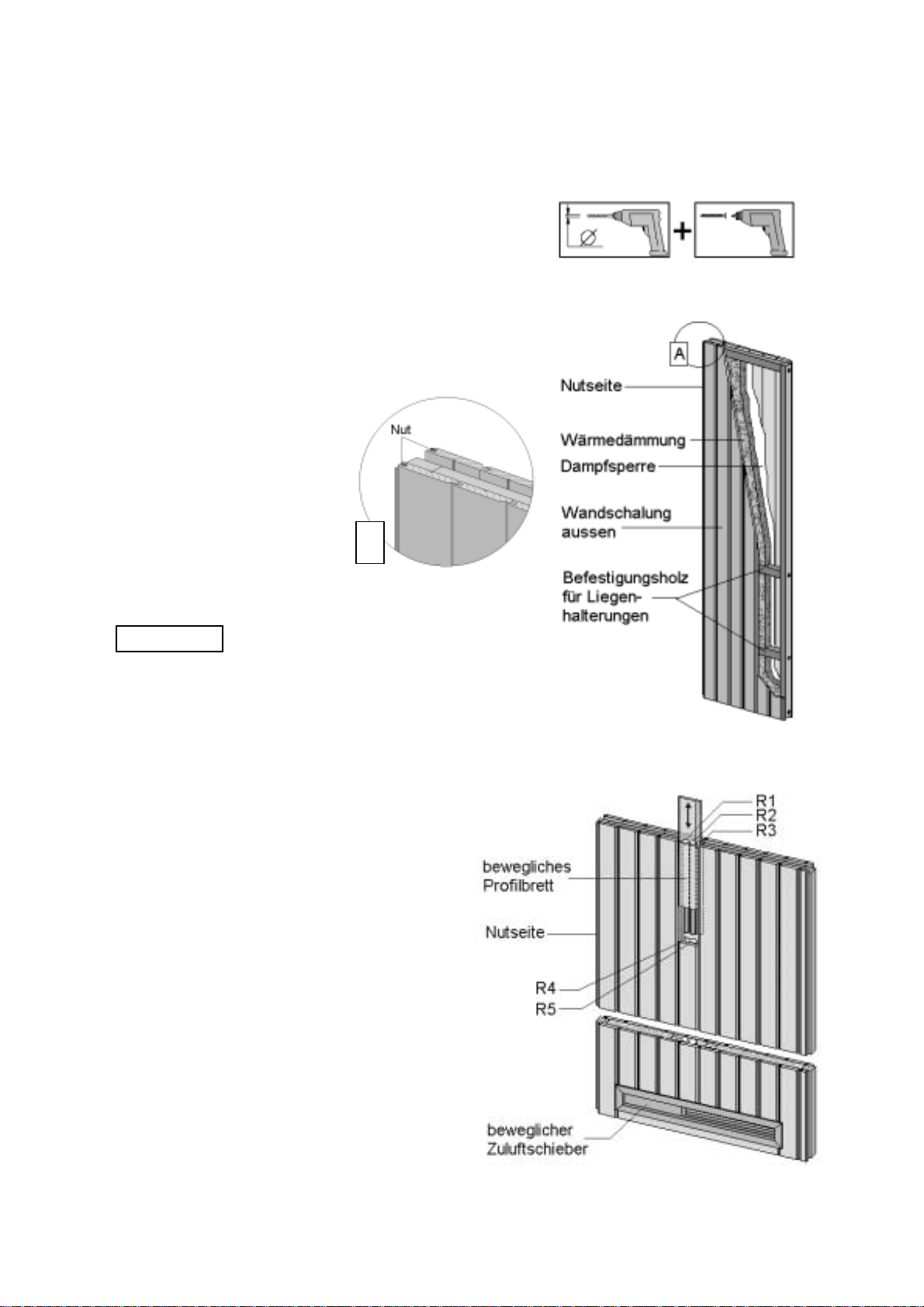
Die Wandelemente bestehen aus sorgfältig ausgesuchtem, nordischen Fichtenholz, die Inneneinrichtung
aus einem Spezialholz mit geringer Wärmeleitfähigkeit. Gesunde Äste, leichte Verfärbungen und kleine
Risse sind für Holz charakteristisch, verleihen der Kabine sein natürliches Aussehen und sind kein
Reklamationsgrund.
Vor der Montage
Für das Aufstellen der Kabine wird eine Mindestraumhöhe von 205 cm benötigt. Der Wandabstand sollte
mindestens 5 cm betragen.
Der Fußboden muss eben und waagerecht sein, da es sonst zu Funktionsstörungen kommen kann.
Am besten eignet sich ein trockener, gut belüftbarer Raum zur Nutzung Ihrer Kabine.
Ein Stein- oder Fliesenboden erweist sich als praktische und zugleich attraktive Fußbodenvariante.
Tipps zur Sicherheit
Achten Sie darauf, dass sich keine Kinder unbeaufsichtigt in der Kabine aufhalten!
Legen Sie keine Gegenstände auf dem Saunaofen ab. - BRANDGEFAHR !
Vergewissern Sie sich bereits vor Beginn der Heizphase, dass sich keine brennbaren Gegenstände in der
Nähe des Ofens befinden.
Verwenden Sie Sauna - Aufgusskonzentrate nur in verdünnter Form. Hinweise über die richtige
Handhabung finden Sie auf den Behältern.
Verwenden Sie keine chemischen Klebstoffe im Inneren der Sauna, sondern allenfalls Holzleim.
Nach Nutzung der Sauna lassen Sie diese bei geöffneter Tür auskühlen. Sorgen Sie stets für eine gute
Durchlüftung des Raumes, in dem sich die Sauna befindet.
Das Hinweisschild Pos. 59 ist gut sichtbar in der Nähe des Saunaofens zu befestigen.
Pflegehinweise
Als Oberflächenbehandlung empfehlen wir Ihnen, die Kabine von außen mit
Bienenwachs oder Holzschutzlasur zu imprägnieren.
Innen erfolgt keine Behandlung.
Die Wandschalung im Innenraum darf nicht abgedeckt werden oder mit Feuchtigkeit in Berührung kommen.
Nach der Nutzung der Kabine lassen Sie diese bei geöffneter Tür auskühlen.
Sorgen Sie stets für eine gute Durchlüftung des Raumes, in dem sich die Kabine befindet.
Bei längerer Nichtbenutzung empfehlen wir, die Kabinentür offen zu halten.
Hartnäckige Schmutzeinwirkungen auf dem Holz können mit Schmirgelpapier entfernt werden.
Technische Änderungen vorbehalten! © copyright weka Holzbau GmbH Neubrandenburg
2
Elektroinstallation
Die Elektroinstallation darf nur von einem zugelassenen Elektrofachmann unter Beachtung der
VDE-und EVU-Richtlinien ausgeführt werden.
Hinweise zur Montage des Saunaofens und des Steuergerätes entnehmen Sie bitte den dort beiliegenden
Montageanleitungen.
Empfehlungen zum Aufbau
Bitte bohren Sie alle Schraubverbindungen vor,
um Beschädigungen an den Holzteilen zu vermeiden!
Folgendes Zeichen macht Sie während der Anleitung
nochmals darauf aufmerksam:
Allgemeiner Aufbau der Wandelemente
Die Abbildung zeigt den
Schnitt durch ein
Wandelement mit beidseitiger
Profilholzschalung.
Alle Wandelemente sind mit
einer Dampfsperre und einer
Wärmedämmung ausgestattet.
Die Dampfsperre muss sich
nach Montage der Sauna immer
direkt hinter der Innenschalung
befinden.
A
Die Innenseite der Wandelemente
ist auf den Rahmenhölzern durch
einen Stempel-Aufdruck
innen →gekennzeichnet.
Achten Sie deshalb vor dem Aufstellen der
einzelnen Elemente darauf, dass sich die
Nutseite (von außen gesehen) immer links befindet !
In die Wandelemente sind Befestigungshölzer für die Liegenhalterungen eingearbeitet.
Diese befinden sind ca. 36cm und 80 cm über dem Boden.
Die Lage dieser Hölzer erkennen Sie an den sichtbaren Schraubenköpfen im Elementrahmen.
Achten Sie darauf, dass sich diese Schraubenköpfe beim Aufstellen jedes Wandelementes in der
unteren Elementhälfte befinden !
Das Zuluftelement enthält im unteren Bereich
einen beweglichen Luftschieber, der es Ihnen
ermöglicht, unabhängig vom Ofentyp eine optimale
Luftzufuhr in der Sauna zu erreichen.
Durch ein bewegliches Profilbrett über
dem kleinen Schlitz im Bereich des
Steuergerätes, erhalten Sie einen leichten
Zugang zu den Leerrohren. Diese dienen
als Montagerohre für die Elektrokabel
der Netzzuleitung, die Saunalampe und
den Saunaofen, ausgehend vom Steuergerät.
R1 : Netzzuleitung -Steuergerät
R2 : Elektroleitung Steuergerät-Saunalampe
R3 : Leitungen für Temperaturfühler
R4 : Leitung Saunaofen-Steuergerät
R5 : Leitung Verdampfer-Steuergerät
( Nur bei Saunadampfbad-Kombiöfen )
Elektroleitungen und Saunalampe sind
nicht im Lieferumfang enthalten, aber als Zubehör erhältlich.
Technische Änderungen vorbehalten! © copyright weka Holzbau GmbH Neubrandenburg
3
Die Sauna kann spiegelverkehrt aufgebaut werden.
Um dem Absenken der Glastür vorzubeugen, ziehen Sie die Imbusschraube der Beschläge fest an.
Achtung:
Das Langloch in Pos. 14 wird zur Kabeldurchführung über dem Zuluftelement benötigt.
Die Montage der Abschlussblenden Pos.29 sollte erst nach Verlegung der Elektro-Kabel erfolgen.
Garantiebestimmungen
Ihre Kabine hat unser Werk nach sorgfältiger Prüfung und Endkontrolle verlassen.
Die Firma weka Holzbau GmbH gewährt Ihnen daher 5 Jahre Garantie auf Konstruktion und
Verarbeitungsqualität. Innerhalb der Garantiezeit werden fehlerhafte Teile kostenlos ersetzt.
Die durch den Austausch entstehenden Kosten sind im Garantieanspruch nicht enthalten.
Garantieansprüche können nur in Verbindung mit Originalpackliste und Originalkaufbeleg in
Anspruch genommen werden.
Von der Garantie sind Mängel ausgeschlossen, die bedingt sind durch:
- unsachgemäßen Untergrund
- nicht gemäß unserer Aufbauanleitung durchgeführten Montage
- gewaltsame Einwirkungen
- eigene Veränderungen an der Kabine
- fehlerhafte Pflege zur Erhaltung der vorhandenen Holzqualität ( siehe Pflegehinweise )
Weitergehende Ansprüche und Folgeschäden fallen nicht unter die Garantiebestimmungen.
Elektrische Bauteile dürfen nur von einem autorisierten Elektriker angeschlossen werden.
Die Garantiezeit für elektrische Bauteile beträgt 2 Jahre. In einem Garantiefall ist die Rechnung des
autorisierten Elektrikers einzureichen, der die Bauteile angeschlossen hat.
Werkzeug
Folgendes Werkzeug sollten Sie vor Beginn der Montage zurecht gelegt haben.
Wasserwaage Rollmaß Bohrmaschine Elektroschrauber Hammer
Feinsäge / Handkreissäge Universalmesser Schraubenschlüssel Imbusschlüssel
Abkürzungen / Symbole:
Abb. Abbildung
cm - Zentimeter
mm - Millimeter
ca. - circa
- Zuluftöffnung
- Abluftöffnung
Technische Änderungen vorbehalten! © copyright weka Holzbau GmbH Neubrandenburg
4
- GB -
Preface
Dear customer
Thank you very much for choosing a weka product.
Read these instructions through completely before assembling your product in order to avoid errors in
assembly or damage.
IMPORTANT
Please use the enclosed packing list to check immediately that your weka product has been
delivered complete and intact.
Please do not dispose of the packing list before the guarantee period has expired. This list enables you to
check that all the individual parts are present. It should be retained along with the proof of purchase. Any
complaints which may arise can probably be easily rectified with this list. The item numbers on the packing
list do not correspond to the item numbers in the following assembly instructions.
We recommend that 2 people carry out the assembly.
In order to prevent accidents, we recommend that children are kept out of the direct vicinity during assembly.
We reserve the right to make further technological developments. This means that there many be minor
deviations in the illustrations.
Please do not simply throw away the packaging material. Paper, card and corrugated board as well as
plastic packaging materials should be placed in the correct collection containers.
Special information
Wood
The wall elements comprise carefully selected Nordic spruce, with the interior panelling constructed from a
special wood with low heat conductivity. Healthy knots, light discoloration and small cracks are characteristic
of the wood, lending the cabin its natural appearance. They are therefore not grounds for complaint.
Prior to assembly
A minimum room height of 205 cm is required to set up the cabin. The wall clearance should be at least
5 cm.
The floor must be level and horizontal, as otherwise it may cause functional interference.
The best location for your cabin would be a dry, well ventilated room.
A stone or tiled floor is both a practical and an attractive floor covering.
Safety tips
Do not place any objects on the sauna furnace – THERE IS A FIRE RISK!
Before the heating phase begins, ensure that no flammable objects are located in the vicinity of the furnace.
Only use the sauna infusion concentrate in diluted form. Information on correct usage can be found on the
containers.
Do not use any chemical adhesives inside the sauna. Only wood glue may be used.
After using the sauna, leave the door open to allow it to cool down. Ensure that the room in which the sauna
is located is well ventilated.
The information plate pos. 59 is to fixed in a clearly visible position near the sauna furnace.
Maintenance
We recommend that you treat the exterior of the sauna with beeswax.
The interior requires no treatment.
The interior wall boarding should not be covered or allowed to come into contact with moisture.
After using the sauna, leave the door open to allow it to cool down.
Ensure that the room in which the sauna is located is well ventilated.
If the sauna is not used for long periods of time, we recommend that the door is kept open.
Stubborn stains on the wood can be removed with emery paper.
Installation of the electrics
The electrics may only be installed by a qualified electrician in accordance with the VDE and EVU guidelines.
Information on assembly of the sauna furnace and the control device can be found in the enclosed assembly
instructions.
Technische Änderungen vorbehalten! © copyright weka Holzbau GmbH Neubrandenburg
5
Assembly recommendations
Please drill pilot holes for all screw connections to avoid damaging the wood. The following symbol in the
instructions will indicate when this is necessary:
General assembly of the wall elements
Figure shows a cross-section through a wall
section with profile wood boarding on both sides.
All wall elements are equipped with a vapour
barrier and heat insulation. After assembly of
the sauna, the vapour barrier must always be
located directly behind the interior boarding.
A
The inner side of the wall element is
indicated on the wooden frame by the
following stamp
innen →.
inside-= innen
Before erecting the individual elements, take
care to ensure that the groove side
(viewed from outside) is always on the left.
Mounting timber has been incorporated into the
wall elements for the bench mountings.
These are located approx. 36 cm and 80 cm above
the floor. The location of this timber can be seen
at the visible screw heads in the element frames.
Each time you install a wall element, ensure that these screw heads are located in the lower half of
the element.
The lower section of the supply air element contains a moveable air vent which makes it possible to achieve
optimal air supply in the sauna, irrespective of furnace type.
A moveable profile board above the small slit near
the control unit provides you with easy access to the
empty tubing. These serve as assembly tubing for the
mains connection electric cable, the sauna lamp and the
sauna furnace ending at the control unit.
R1 : Mains connection control unit
R2 : Control unit sauna lamp electrical cable
R3 : Cables for temperature sensors
R4 : Sauna furnace control unit
R5 : Vaporiser control unit cable
(Only with sauna steam bath combi furnaces)
Electric cables and a sauna lamp
are not included in the scope of the
delivery but are available as accessories.
The sauna can also be built in its mirror image.
To prevent the dropping of the glass door,
tighten the allen screw of the braces firmly.
Note:
The long hole in pos. 14 is required for the cable penetration above the supply air element.
The assembly of the bargeboards pos 29 should only be carried out once the electric cable has been laid.
Technische Änderungen vorbehalten! © copyright weka Holzbau GmbH Neubrandenburg
6
Guarantee conditions
Your cabin left our factory after being carefully checked and subjected to a final check. weka Holzbau GmbH
provides you with a 5-year guarantee for design and processing quality. Within the guarantee time, faulty
parts will be replaced free of charge. Costs arising as a result of the exchange are not included in the
guarantee claim.
Guarantee claims may only be made in conjunction with the original packing list and proof of
purchase.
Excluded from the guarantee are defects caused by:
- improper subsoil
- assembly not carried out in accordance with our instructions
- violent forces
- your own alterations to the cabin
- defective care in the maintenance of the current wood quality (see care instructions)
Further claims and consequential damage do not fall under the guarantee regulations.
Electrical components may only be connected by an authorised electrician.
The guarantee period for electrical components is 2 years. Should a claim be made against the guarantee,
the invoice from the electrician who connected the components is to be submitted.
You should have the following tools to hand before beginning assembly.
Spring tape Elektric
Spirit level measure Drill screwdriver Hammer
Mitre saw/
hand disk saw Universal cutter Spanner Allen key
Abbreviations / Symbols
Abb. Figure
cm - Centimetre
mm - Millimetre
ca. - approximately/approx.
- Supply air
- Outgoing air
Technische Änderungen vorbehalten! © copyright weka Holzbau GmbH Neubrandenburg
7
-F-
Avant-propos
Chère Cliente, cher Client
Nous vous remercions d'avoir choisi un produit weka.
Lisez entièrement la présente notice avant de procéder à l'assemblage afin d'éviter les erreurs et les
dommages.
IMPORTANT !
Veuillez vérifier immédiatement, à l'aide de la liste des pièces, si le produit weka est
arrivé complet et en bon état.
Ne détruisez la liste des pièces qu'une fois la garantie écoulée. Cette liste vous permet de vérifier si les
pièces détachées sont complètes et doit être conservée avec le justificatif d'achat. Elle vous permettra de
faire valoir aisément d'éventuelles réclamations. Les numéros de pos. de la liste des pièces ne sont pas
identiques aux numéros de pos. de la présente notice de montage.
Nous vous recommandons d'effectuer le montage à 2 personnes.
Afin de prévenir tout accident, éviter la présence d'enfants à proximité durant le montage.
Nous nous réservons le droit d'apporter aux produits des modifications dans le cadre de l'évolution
technique.
De légères différences sont par conséquent possibles par rapport aux illustrations.
Ne pas jeter simplement le matériel d'emballage! Les emballages en papier, carton et carton ondulé doivent
être déposés dans le container de tri correspondant.
Consignes spécifiques
Le bois
Les éléments constitutifs des parois se composent de sapin nordique soigneusement sélectionné et
l'équipement intérieur d'un bois spécial à faible conductibilité thermique. Les noeuds robustes, les légères
décolorations et les petites fissures sont typiques du bois, confèrent aux cabines leur aspect naturel et ne
constituent pas un motif de réclamation.
Avant le montage
L'installation de la cabine nécessite une hauteur sous plafond minimale de 205 cm. La distance aux murs
doit être d'au moins 5 cm.
Le sol doit être plan et horizontal sous peine de risques de dysfonctionnement.
La cabine sera utilisée au mieux dans un local sec et bien aéré.
Les sols en pierre ou en carrelage sont tout à la fois pratiques et esthétiques.
Conseils de sécurité
Ne déposez pas d'objets sur le four du sauna. - DANGER D'INCENDIE !
Assurez-vous, dès le début de la phase de chauffe, qu'aucun objet inflammable ne se trouve à proximité du
four.
N'utilisez les concentrés pour sauna que sous forme diluée. Les informations nécessaires pour leur bonne
utilisation figurent sur les récipients.
N'utilisez pas de colles chimiques à l'intérieur du sauna mais tout au plus de la colle à bois.
Après l'utilisation, laissez le sauna refroidir avec la porte ouverte. La pièce dans laquelle se trouve le sauna
doit toujours être bien aérée.
La plaque d'information Pos. 59 doit être fixée à un endroit bien visible à proximité du four du sauna.
Consignes d'entretien
Nous vous recommandons pour les traitement des surfaces d'imprégner la cabine de l'extérieur avec de la
cire d'abeille.
Aucun traitement n'est à réaliser à l'intérieur.
Le coffrage de paroi ne doit pas être masqué à l'intérieur ou entrer en contact avec l'humidité.
Après utilisation, laissez refroidir la cabine avec la porte ouverte.
Assurez toujours une bonne ventilation de la pièce dans laquelle se trouve la cabine.
En cas de non utilisation prolongée, nous recommandons de garder la porte de la cabine ouverte.
Les incrustations tenaces de saletés sur le bois peuvent être éliminées avec un papier abrasif.
Technische Änderungen vorbehalten! © copyright weka Holzbau GmbH Neubrandenburg
8
Installation électrique
L'installation électrique doit être effectuée uniquement par un électricien agréé, en respect des normes de
l'union des électriciens allemands VDE et de l'entreprise de fourniture d'électricité.
Pour les informations relatives au montage du four du sauna et de l'unité de commande, veuillez vous
référer aux notices de montage correspondantes.
Recommandations pour le montage
Pré-percez tous les assemblages vissés afin d'éviter d'endommager les éléments en bois!
Ceci vous est rappelé par le symbole suivant dans la notice:
Composition générale des
éléments constitutifs des parois
L'illustration montre une vue en coupe
d'un élément de paroi muni sur les
deux côtés d'un coffrage de bois
profilé. Tous les éléments constitutifs
des parois sont équipés d'un pare-vapeur
et d'une isolation thermique.
Le pare-vapeur doit toujours se trouver
directement derrière le coffrage inférieur
lorsque le sauna a été monté.
A
L'intérieur des éléments constituant les parois
est repéré sur les bois équarris par le cachet
Innen →.
intérieur = Innen
Par conséquent, avant de mettre en place
les différents éléments, assurez-vous que le
côté rainuré (vu de l'extérieur) se trouve toujours
à gauche!
Les éléments constitutifs des parois comportent des pièces de fixation pour les supports des couchettes.
Elles se trouvent à env. 36 cm et 80 cm du sol. La position de ces pièces est reconnaissable aux têtes
de vis apparentes dans le cadre des éléments.
Assurez-vous que ces têtes de vis se trouvent
dans la moitié inférieure des éléments lors
de la mise en place de chaque élément de paroi !
L'élément d'arrivée d'air présente au bas un clapet
d'air mobile qui permet d'optimiser l'arrivée d'air
à l'intérieur du sauna indépendamment du type de four.
Une planche profilée mobile qui se trouve
au-dessus de la petite fente au niveau
de l'unité de commande vous permet d'accéder
facilement aux tubes vides. Ces derniers servent
de tubes de montage pour les câbles électriques
d'alimentation, la lampe du sauna et le four du sauna,
en partant de l'unité de commande.
R1 : câble secteur unité de commande
R2 : câble électrique unité de commande lampe du sauna
R3 : câbles pour les sondes de température
R4 : câble four du sauna unité de commande
R5 : câble évaporateur unité de commande
(uniquement dans le cas des fours mixtes des
saunas bains de vapeur)
Les câbles électriques et la lampe du sauna ne sont pas fournis mais sont disponibles en accessoires.
Technische Änderungen vorbehalten! © copyright weka Holzbau GmbH Neubrandenburg
9
Attention:
Le trou oblong de la pos. 14 est nécessaire pour le passage de câble au-dessus de l'élément
d'arrivée d'air.
Les caches décoratifs pos.29 ne doivent être montés qu'après la pose des câbles électriques.
Le sauna peut être assemblé de manière symétriquement opposée.
Afin de prévenir l'affaissement de la porte en verre, vissez fortement la vis à six pans creux des ferrures.
Clauses de garantie
Votre cabine a été soumise à une vérification approfondie et à un contrôle final avant de quitter notre usine.
weka Holzbau GmbH accorde par conséquent une garantie de 5 ans sur la construction et la qualité de
fabrication. Au cours de la période de garantie, les pièces défectueuses sont remplacées gratuitement.
Les coûts liés au remplacement ne sont pas couverts par la garantie.
L'original de la liste des pièces et l'original du justificatif d'achat sont nécessaires pour faire valoir
tous droits relatifs à la garantie.
La garantie ne couvre pas les vices dus à:
- un support non conforme
- un montage non conforme à nos instructions
- l'emploi de la force
- des modifications apportées à la cabine
- un manque d'entretien en vue du maintien de la qualité du bois (voir les instructions
d'entretien)
Les autres droits et dommages secondaires n'entrent pas dans le cadre des clauses de
garantie.
Le raccordement des composants électriques doit être effectué uniquement par un électricien agréé.
Les composants électriques sont garantis 2 ans. En cas de recours à la garantie, la facture de l'électricien
agréé qui a procédé au raccordement des composants doit être produite.
Pour le montage, nous vous recommandons de préparer les outils suivants.
décamètre visseuse
niveau à bulle à ruban perceuse électrique marteau
scie à denture fine / clé pour vis à
scie circulaire couteau universel clé six pans creux
Abréviations / Symboles :
Abb. - figure
cm - centimètres
mm - millimètres
ca. - environ / env.
- air amené
- air sortant