Welbilt Multiplex APKV3D User manual

Part Number: 020006402
September 7, 2023
Air Compressors
Systems & Kits
Installation, Operation and Maintenance Manual
Original Instructions — This manual is updated as new information and models are released.
Visit www.welbilt.com for the latestmanual.
,Caution
To Reduce the Risk of Electric Shock or Injury, Use Indoor Only.

Safety Notices
As you work on Multiplex equipment, be sure to pay close
attention to the safety notices in this manual. Disregarding
the notices may lead to serious injury and/or damage to the
equipment.
Throughout this manual, you will see the following types of
safety notices:
DANGER
Text in a Danger box indicates a hazardous situation
that, if not avoided, will result in serious injury or death.
This applies to the most extreme situations.
nWarning
Text in a Warning box alerts you to a potential personal
injury situation. Be sure to read the Warning statement
before proceeding, and work carefully.
,Caution
Text in a Caution box alerts you to a situation in which
you could damage the equipment. Be sure to read
the Caution statement before proceeding, and work
carefully.
Notice
Text in a Notice indicates information considered
important, but not hazard related (e.g. messages
relating to property damage)..
Procedural Notices
As you work on Multiplex equipment, be sure to read the
procedural notices in this manual. These notices supply
helpful information which may assist you as you work.
Throughout this manual, you will see the following types of
procedural notices:
Important
Text in an Important box provides you with information
that may help you perform a procedure more efficiently.
Disregarding this information will not cause damage or
injury, but it may slow you down as you work.
NOTE: Text set off as a Note provides you with simple, but
useful, extra information about the procedure you are
performing.
Read These Before Proceeding:
,Caution
Proper installation, care and maintenance are essential
for maximum performance and trouble-free operation
of your Multiplex equipment. Read and understand
this manual. It contains valuable care and maintenance
information. If you encounter problems not covered
by this manual, do not proceed, contact Manitowoc
Foodservice. We will be happy to provide assistance.
Important
Routine adjustments and maintenance procedures
outlined in this manual are not covered by the warranty.
nWarning
PERSONAL INJURY POTENTIAL
Do not operate equipment that has been misused,
abused, neglected, damaged, or altered/modified from
that of original manufactured specifications.
NOTE: SAVE THESE INSTRUCTIONS.
We reserve the right to make product improvements at
any time. Specifications and design are subject to change
without notice.

Table of Contents
Part Number: 020006402 3
Section 1
General Information
Read This Manual.............................................................................................................. 5
About the Air Compressor ................................................................................................. 5
Unit Inspection.................................................................................................................. 5
Model & Serial Numbers ................................................................................................... 5
Serial Number Location................................................................................................... 5
Warranty Information........................................................................................................ 5
Specifications .................................................................................................................... 6
Dimensions...................................................................................................................... 6
Capacity & Weight........................................................................................................... 6
Location........................................................................................................................... 7
Electrical.......................................................................................................................... 8
Pressure Settings & Location........................................................................................... 9
Section 2
Installation
Step-by-Step Installation ................................................................................................. 11
Pre-installation Checklist............................................................................................... 11
Basic Setup .................................................................................................................... 12
Post Installation Checklist .............................................................................................12
Air Compressor Kit with Change-over Valve and Dump Valve — P.N. 00212135 (120 VAC),
P.N. 00214969 (120 VAC), P.N. 00217555 (230 VAC) ......................................................... 13
Grounding instructions ................................................................................................. 13
Fountain Systems Applications......................................................................................13
Beer Systems Applications ............................................................................................15
Air Pump & Tank with Change-over Valve & Dump Valve Kit — P.N. 00212145 (220V),
P.N. 00214971 (220V) ...................................................................................................... 16
Installation of model 44X refrigeration unit..................................................................17
Electrical Connections................................................................................................... 17
Connecting the Air Pump to the Stand Outlet Box........................................................ 18
Connecting the air pump to the wall outlet.................................................................. 18
Air Tank Retro-fit Kit — P.N. 00212053............................................................................. 19
Removing old tank ........................................................................................................ 19
Installing the new air compressor tank ......................................................................... 19
Start-up ......................................................................................................................... 19
Attaching Air Pump to Mounting Bracket — P.N. 00202676.............................................. 20
Opening the cartons...................................................................................................... 20
Installing the mounting bracket ....................................................................................20
How to attach the air pump to the mounting bracket .................................................. 20
Section 3
Operation
Component Identification................................................................................................ 21
Normal Operation ........................................................................................................... 21
Features ........................................................................................................................ 21

4 Part Number: 020006402
Table of Contents (continued)
Section 4
Maintenance
General Maintenance ...................................................................................................... 23
Draining of the tank ...................................................................................................... 23
Storage .......................................................................................................................... 23
Section 5
Troubleshooting
Before Calling For Service Checklist ................................................................................. 25
Testing for leaks............................................................................................................. 25

Part Number: 020006402 5
Read This Manual
Welbilt developed this manual as a reference guide for the
owner/operator and installer of this equipment. Please read
this manual before installation or operation of the machine.
A qualified service technician must perform installation and
start-up of this equipment. Consult Section 5 within this
manual for service assistance.
If you cannot correct the service problem, call your Service
Agent or Distributor. Always have your model and serial
number available when you call.
Your Service Agent _______________________________
Service Agent Telephone Number____________________
Your Local Distributor______________________________
Distributor Telephone Number ______________________
Model Number __________________________________
Serial Number ___________________________________
Installation Date _________________________________
About the Air Compressor
Provides clean uncontaminated compressed air from a
stainless steel storage tank. Compressors can be used to
drive pneumatic syrup pumps or propel draft beer in a high
volume location.
Unit Inspection
Thoroughly inspect the unit upon delivery. Immediately
report any damage that occurred during transportation
to the delivery carrier. Request a written inspection report
from a claims inspector to document any necessary claim.
See “Pre-installation Checklist”on page 11.
nWarning
Do not damage the air circuits when installing,
maintaining or servicing the unit.
nWarning
Do not operate equipment that has been misused,
abused, neglected, damaged, or altered/modified from
that of original manufactured specifications.
This appliance is not intended for use by persons
(including children) with reduced physical, sensory
or mental capabilities, or lack of experience and
knowledge, unless they have been given supervision
concerning use of the appliance by a person responsible
for their safety.
Model & Serial Numbers
This manual covers the following models:
Air Compressor Systems
APKV3D, APH3, APKV3X, APH3X
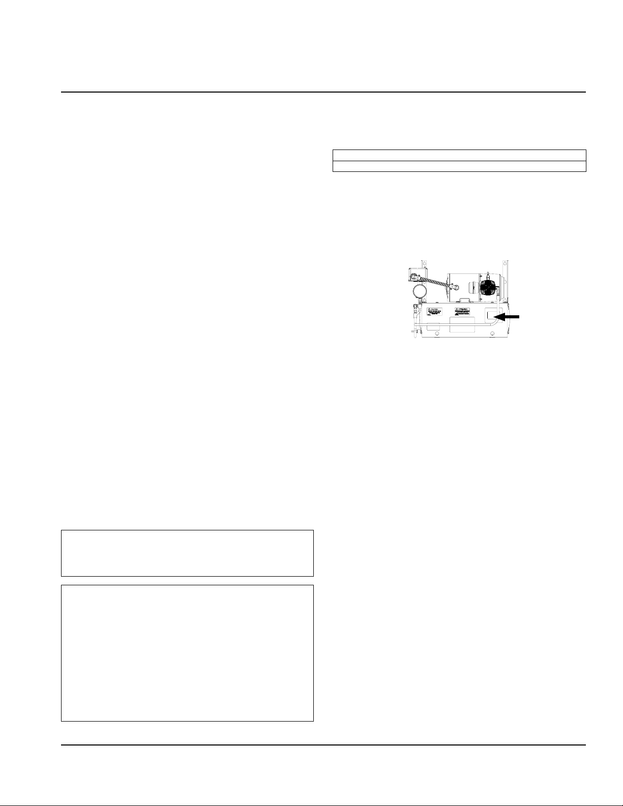
SERIAL NUMBER LOCATION
The Air Compressor system serial tag is printed on the front
lower right corner. Always have the serial number of your
unit available when calling for parts or service.
Serial Tag Location
Warranty Information
Consult your local Service Agent or Representative for terms
and conditions of your warranty. Your warranty specifically
excludes all general adjustments, cleaning, accessories and
related servicing.
Your warranty should be activated at the time of
installation/registration or a card must be returned to
activate the warranty on this equipment. If either method
is not completed, the warranty period can begin when the
equipment leaves the Welbilt factory.
No equipment may be returned to Welbilt without a written
Return Materials Authorization (RMA). Equipment returned
without an RMA will be refused at Welbilt’s dock and
returned to the sender at the sender’s expense.
Please contact your local distributor for return procedures.
Section 1
General Information

6 Part Number: 020006402
General Information Section 1
Specifications
DIMENSIONS
Side ViewFront View
A
BC
A 15.25" (39 cm) B 19.25" (49 cm) C 7.75" (20 cm)
nWarning
To avoid instability the installation area must be capable
of supporting the weight of the equipment. Additionally
the equipment must be level side to side and front to back.
CAPACITY & WEIGHT
Model Voltage Capacity Compressor HP Full Operating
Weight
APKV3D, APH3, 120V 3 Gallon Stainless Steel Tank
(Provides 36/ft3 hour capacity) 1/4 HP Motor
37.8 lbs
(17.1kg)
APKV3X, APH3X 220V 43.8 lbs
(19.9kg)

Part Number: 020006402 7
Section 1 General Information
LOCATION
The location selected for the Air Compressor System must
meet the following criteria.
• The air temperature must be at least 40°F (4°C), but
must not exceed 90°F (32°C), climate class 4.
• Indoors, the location must not be near heat-generating
equipment or in direct sunlight and must be protected
from weather..
• Verify floor of install location is level front to back, side
to side.
• Keep equipment area clear of combustible material.
Clearances
Top 0” (0 cm)
Sides 0" (0 cm)
Back 0”(0 cm)
Front 12" (31 cm)
nWarning
Do not obstruct machine vents or openings.

8 Part Number: 020006402
General Information Section 1
ELECTRICAL
nWarning
All wiring must conform to local, state and national codes.
Minimum Circuit Ampacity
The minimum circuit ampacity is used to help select the
wire size of the electrical supply. (Minimum circuit ampacity
is not the Air Compressor System’s running amp load.)
The wire size (or gauge) is also dependent upon location,
materials used, length of run, etc., it must be determined by
a qualified electrician.
Voltage
A dedicated electrical circuit is required, a power cord
is provided with all units. Some models are available in
different voltages and may be equipped with a different
plug. Refer to the Air Compressor System Model/Serial Plate
for voltage/amperage specifications.
Minimum Circuit Amperage Chart
Important
Due to continuous improvements, this information is
for reference only. Please refer to the serial number tag
to verify electrical data. Serial tag information overrides
information listed on this page.
Model Voltage/Cycle/
Phase
Total Amps Breaker Size
(Min/Max)
APKV3D 120/60/1 7A
15A
APH3
APKV3X 220/60/1 3.5A
APH3X
• Dedicated 15A Circuit
• 120V comes with NEMA 5 - 15 Plug
• Cord length
APKV3D APH3 (120V) = 96.5”(245 cm)
APKV3X APH3X (220V) = 69”(175 cm)
Grounding Instructions
nWarning
The machine must be grounded in accordance with
national and local electrical codes.
This appliance must be grounded. In the event of
malfunction or breakdown, grounding provides a path
of least resistance for electric current to reduce the
risk of electric shock. This appliance is equipped with a
cord having an equipment-grounding conductor and
a grounding plug. The plug must be plugged into an
appropriate outlet that is properly installed and grounded
in accordance with all local codes and ordinances.
nWarning
When using electric appliances, basic precautions must
always be followed, including the following:
A. Read all the instructions before using the
appliance.
B. To reduce the risk of injury, close supervision
is necessary when an appliance is used near
children.
C. Do not contact moving parts.
D. Only use attachments recommended or sold by
the manufacturer.
E. Do not use outdoors.
F. For a cord-connected appliance, the following
must be included:
• Do not unplug by pulling on cord. To unplug,
grasp the plug, not the cord.
• Unplug from outlet when not in use and
before servicing or cleaning.
• Do not operate any appliance with a
damaged cord or plug, or after the appliance
malfunctions or is dropped or damaged in
any manner. Contact the nearest authorized
service facility for examination, repair, or
electrical or mechanical adjustment.
G. Follow applicable lock out tag out procedures
before working on equipment.
H. Connect to a properly grounded outlet only. See
Grounding Instructions.

Part Number: 020006402 11
Step-by-Step Installation
These instructions are provided to assist the qualified
installer. Contact your Welbilt Service Agent or call Welbilt
for information regarding start-up services.
Important
Failure to follow these installation guidelines may affect
warranty coverage.
nWarning
To Avoid Serious Injury
DO Adhere to all National and Local Plumbing and
Electrical Safety Codes.
DO Turn “off” incoming electrical service switches when
servicing, installing, or repairing equipment.
DO Check that all flare fittings on the carbonation
tank(s) are tight. This check should be performed with a
wrench to ensure a quality seal.
DO Inspect pressure on regulators before starting up
equipment.
DO Protect eyes when working around refrigerants.
DO Use caution when handling metal surface edges of
all equipment.
DO Handle CO2cylinders and gauges with care. Secure
cylinders properly against abrasion.
DO Store CO2cylinder(s) in well ventilated areas.
DO NOT Throw or drop a CO2cylinder. Secure the
cylinder(s) in an upright position with a chain.
DO NOT Connect the CO2cylinder(s) directly to the
product container. Doing so will result in an explosion
causing possible death or injury. It is best to connect the
CO2cylinder(s) to a regulator(s).
DO NOT Store CO2cylinders in temperature above 125°F
(51.7°C) near furnaces, radiator or sources of heat.
DO NOT Release CO2gas from old cylinder.
DO NOT Touch refrigeration lines inside units. Some
may exceed temperatures of 200°F (93.3°C).
DANGER
Carbon Dioxide (CO2) displaces oxygen. Exposure to a
high concentration of CO2gas causes tremors, which
are followed rapidly by loss of consciousness and
suffocation. If a CO2gas leak is suspected, particularly
in a small area, immediately ventilate the area before
repairing the leak. CO2lines and pumps must not be
installed in an enclosed space. An enclosed space can
be a cooler or small room or closet. This may include
convenience stores with glass door self serve coolers. If
you suspect CO2may build up in an area, venting of the
B-I-B pumps and / or CO2monitors must be utilized.
nWarning
Danger of Electric Shock
Disconnect and lock out all electrical power sources
before performing service or maintenance on this
machine — except when electrical tests are being
performed by qualified service personnel.
PREINSTALLATION CHECKLIST
Any damage should be noted and reported to the
delivering carrier immediately.
Visually inspect the package and compressor
housing. Be sure lines are secure and intact.
Inspect installation location behind the unit for
electrical outlet location, air hose fittings.
Check voltage at outlet dedicated for the Air
Compressor unit.
Verify floor or shelf of install location is level front
to back, side to side.
nWarning
The mass of this appliance may allow it to move
uncontrolled on an inclined surface. Adequate means
must be provided to prevent uncontrolled movement
at all times.
Section 2
Installation

12 Part Number: 020006402
Installation Section 2
BASIC SETUP
Locate the air compressor according to the following
guidelines:
• Unit is intended for indoor use only.
• Position the air compressor near a
grounded electrical outlet (see GROUNDING
INSTRUCTIONS, See “Grounding Instructions” on
page 8.)
• The unit in it’s normal operating position, the
drain shall be the lowest portion of a tank and
mounted as shown.
Drain
• The air compressor must be at least 12 inches
(31 cm) in front from any wall or obstruction, in
a clean, well-ventilated area, to insure sufficient
air flow and cooling.
• Keep unit area clear of combustible material.
• Do not install the unit directly over a drain.
Steam rising up out of the drain will adversely
affect operation, air circulation, and damage
electrical/electronic components.
• Do not install in an area where a high-pressure
water jet could be used for cleaning.
• Connect appropriate outlet lines the air
compressor will supply.
POST INSTALLATION CHECKLIST
Is air pressure within proper range?
Is the machine cycling ON/OFF properly?
Has the owner/operator been instructed regarding
maintenance procedures?
Has the owner/operator completed the warranty
registration card?
Once completed, the Air Compressor is ready for use.

Part Number: 020006402 13
Section 2 Installation
Air Compressor Kit with Change-over Valve and Dump Valve — P.N. 00212135 (120 VAC),
P.N. 00214969 (120 VAC), P.N. 00217555 (230 VAC)
These instructions cover the installation and initial start-up
of the Multiplex Air Compressor Kit. An appropriate 3-wire,
15 amp power receptacle must be provided within 5 ft
(152.4 cm) of the left end of the refrigeration unit. This kit
is for use with either the Model 44 or Model 50 Fountain
Refrigeration Units and any of the Beermaster Units. Refer
to appropriate section for instructions.
GROUNDING INSTRUCTIONS
This product should be grounded. In the event of an
electrical short circuit, grounding reduces the risk of electric
shock by providing an escape wire for the electric current.
This product is equipped with a cord having a grounding
wire with an appropriate grounding plug. The plug
must be plugged into an outlet that is properly installed
and grounded in accordance with all local codes and
ordinances. See “Grounding Instructions” on page 8
DANGER
Improper installation of the grounding plug can result
in a risk of electric shock. If repair or replacement of the
cord or plug is necessary, do not connect the grounding
wire to a flat blade terminal. The wire with insulation
having an outer surface that is green with or without
yellow stripes is the grounding wire.
Check with a qualified electrician or serviceman if the
grounding instructions are not completely understood, or
if in doubt as to whether the product is properly grounded.
Do not modify the plug provided; if it will not fit the outlet,
have the proper outlet installed by a qualified electrician.
Do not use an extension cord or an adapter plug with this
equipment.
FOUNTAIN SYSTEMS APPLICATIONS
Refrigeration Unit
Air Compressor
Mounting Channel
Stand
Pump
Assembly
Mounting the Air Compressor onto a
Multiplex Support Stand
Installing the air compressor onto the support stand
1. Mount the air compressor mounting channel to left
end of the Multiplex Support Stand with two (2) 1/4”-
20 nuts and screws provided with kit (refer to figure
above).
NOTE: Compressor may be mounted to the end of the
refrigeration unit.
2. Install the air compressor assembly to the support
stand and mounting channel with four (4) 1/4”-20 nuts
and screws provided with kit (refer to figure above).
NOTE: Do not plug in pump assembly at this time. Shut“off”
the main CO2supply to refrigeration unit.
Pump Assembly
Refrigeration
Unit
Mounting the Air Compressor onto a
Multiplex Refrigeration Unit

14 Part Number: 020006402
Installation Section 2
Installing the air compressor onto a refrigeration unit
1. Align the air compressor assembly over the four (4)
holes on left end of the Multiplex Refrigeration Unit.
Secure to unit using the four (4) 1/4”screws provided in
kit (refer to figure above).
NOTE: Do not plug in pump assembly at this time. Shut“off”
main CO2supply to refrigeration unit.
2. Locate the Air/CO2Change-over Valve Assembly
supplied with kit (P.N. 00212506). Align the mounting
bracket of the change-over valve over the mounting
holes on the control panel (location for change-over
valve will be marked“Air/CO2Change-over Valve”).
Mount the air/co2change-over valve to the panel
with the #10-32 screws provided in kit (refer to figure
below).
To Outlet Fitting
of Air Pump
Air/CO2Change-over
Valve
To Syrup Tank
Supply Manifold
To CO2Supply
Manifold
CO2Control Panel
Installing the optional dump valve onto the Multiplex
refrigeration unit
1. Connect the 1/4”line assembly provided in kit (P.N.
00212506) to the flare fitting on right side of air/CO2
change-over valve. Route the other end of tubing
to the CO2supply manifold. Trim excess line and
connect swivel nut adapter to the remaining end of
line assembly. Secure with tab clamp. Connect the line
assembly to the CO2supply manifold (refer to figure
below).
8 ft Length of Tubing
to Floor Drain
3 ft Length
of Tubing
Dump Valve
Air Tank
Compression
Elbow
Mounting the Dump Valve onto the
Multiplex Refrigeration Unit
2. Locate the 4-1/2”section of 1/4” tubing connected at
bottom side of change-over valve. Route and connect
the remaining end of tubing to the syrup tank supply
manifold (refer to figure above).
3. Locate the 12 ft x 1/4”EVA line assembly provided in
air compressor kit. Attach the end of this line assembly,
with the swivel nut, to the outlet fitting of the air
compressor tank. Use 1/4”flare washers at swivel nut
connectors. Neatly route tubing under the stand top
and to the left side of the control panel. Connect the
line assembly with 1/4”elbow x barb (provided in kit
P.N. 00212506) to the 1/4”male flare fitting of the air/
CO2change-over valve (refer to figure above).
4. Locate the dump valve supplied with kit. Mount the
dump valve with #10-32 self-tapping screws provided
with kit to lower left cross channel of support stand.
5. Locate the 3 ft length of tubing supplied with kit.
Neatly route and attach this line from the air tank
compression elbow to the shut-off valve compression
fitting located on top of the dump valve. Trim tubing to
correct length. Tighten compression nuts.
6. Locate the 8 ft length of tubing supplied with kit. Route
and connect this line from the 1/4”barb elbow of the
dump valve to a floor drain. Place the shut-off valve
handle in the“open”position (refer to figure above).
7. Plug the air pump power supply cord into the power
receptacle provided on wall. Pump will begin to run
immediately and shut“off” when tank pressure reaches
approximately 90 psi (6.2 bar). Pump will turn “on”when
tank pressure drops to 70 psi (4.8 bar). If not, adjust
pressure switch according to instructions located on
the inside of pressure switch cover.
8. Turn the air/CO2change-over valve to the “Air” position.
Check for leaks.

Part Number: 020006402 15
Section 2 Installation
BEER SYSTEMS APPLICATIONS
Beermaster Unit
Air Compressor
Mounting Channel
Stand
Pump
Assembly
Mounting the Air Compressor onto
the Beermaster™ Unit
Procedure for installing the air compressor onto a
Beermaster™ unit
1. Determine location where the air pump will be
installed.
NOTE: Install the air compressor wall mount bracket (if
applicable).
2. Install the air compressor in its final location with
proper hardware.
3. Mount the low pressure regulator (packed separately)
to a convenient location. Attach the 10 ft x 1/4” ID air
line (provided with air compressor) to the air pump
outlet fitting. Route and connect the remaining end of
the air line to the inlet and onto the outlet of the low
pressure regulator. Route and connect the remaining
end of the tubing to the inlet side of the air filter
assembly.
4. Connect one (1) end of the remaining section of the air
line to the outlet side of the air filter assembly. Route
and connect the opposite end of the air line to the
incoming air connection on the left side of the blender.
5. Attach the 10 ft x 3/8”ID drain line to the tank drain
fitting and route opposite end to floor drain.
6. Close tank outlet valve and plug air compressor into a
120 VAC outlet (domestic).
NOTE: Allow tank to fill completely and shut“off”.
Compressor should shut“off”at approximately 70 psi
(4.8 bar). Compressor will start up when tank pressure drops
to approximately 50 psi (3.1 bar).
7. Open tank outlet valve and adjust air compressor
regulator to 40 psi (2.8 bar).

16 Part Number: 020006402
Installation Section 2
Air Pump & Tank with Change-over Valve & Dump Valve Kit — P.N. 00212145 (220V),
P.N. 00214971 (220V)
These instructions cover the installation of the 220V/50Hz
Multiplex Air Pump kit. This kit is designed to be used with
the Model 44X. The air pump must be mounted to the
support stand with a minimum of a 6-inch clearance.
1. Mount air compressor mounting channel to left side of
stand in the third hole down with two 1/4-20 nuts and
screws provided with kit. (See figure below)
2. Install pump/tank assembly to stand and mounting
channel with four 1/4-20 nuts and screws provided
with kit. (See figure below)
1/4" ID Tube
(Use 3 Ft.)
Air Pump Tank
Compression
Elbow
Shutoff
Valve
Air Compressor
Mounting
Channel
8 ft. (2.44 m) Length" of
Tubing to Floor Drain
Pump Tank
Assembly
Stand
Dump Valve
Installation

Part Number: 020006402 17
Section 2 Installation
INSTALLATION OF MODEL 44X REFRIGERATION UNIT
1. Shut off main CO2supply to refrigeration unit.
2. Locate the air/CO2change-over valve assembly
supplied with kit P.N. 212506. Align the mounting
bracket of the change-over valve over the mounting
holes on control panel (Location for changeover valve
will be marked “Air/CO2Change-over Valve”). Mount the
air/CO2change-over valve to the panel with the #10-32
screws provided in kit. (See figure below)
To CO2Supply
Manifold
Air/ CO2
Changeover
Valve
To Outlet Fitting
of Air Pump
To Syrup
Tank Supply
Manifold
Model 44X Manifolds
3. Locate the 1/4”(6.35 mm) EVA line connected at the
CO2supply manifold and syrup tank manifold. Remove
and discard the line.
4. Connect the 1/4”(6.35 mm) line assembly provided in
kit P.N. 212506 to the flair fitting on the right side of the
air/CO2change-over valve. Route the other end of the
tubing to the CO2supply manifold. Trim excess line and
connect swivel nut adapter to the remaining end of
line assembly. Secure with tab clamps. Connect this line
assembly to the CO2supply manifold. (See figure above).
5. Locate the 4-1/2”(11.4 cm) section of 1/4” (6.35 mm)
tubing and connect to the bottom side of the air/CO2
change-over valve. Route and connect the remaining
end of tubing to the syrup tank supply manifold. (See
figure above)
6. Locate the 12’x 1/4”(3.66 m x 6.35 mm) EVA line
assembly provided in kit P.N. 212506. Attach the end
of this line assembly, with the swivel nut, to the outlet
fitting of the air compressor tank. Neatly route tubing
under the stand top and to the left side of the control
panel. Connect the line assembly with 1/4”(6.35 mm)
elbow x barb (provided in kit P.N. 212506) to the 1/4”
(6.35 mm) male flare fitting of the air/CO2change-over
valve. (See figure above).
7.
8. Locate the dump valve supplied with kit. Mount the
dump valve with #10-32 self-tapping screws provided
with kit to lower left cross channel of support stand.
Use holes provided in channel. (See Installation figure)
9. Locate the six foot (1.83 m) length of tubing supplied
with kit. Neatly route and attach this line from the air
compressor tank compression elbow to the shutoff
valve compression fitting located at top of the dump
valve. Trim tubing to correct length. (See Installation
figure)
10. Locate the eight foot (2.44 m) length of tubing supplied
with kit. Route and connect this line from the 1/4”
(6.35 mm) barb elbow of the dump valve to a floor
drain. Place the shutoff valve handle in the open
position. (See Installation figure)
11. Connect the cord to the stand outlet box or the wall
outlet, following the appropriate steps listed below.
ELECTRICAL CONNECTIONS
This air pump kit is designed to easily connect to the high
stand that supports the refrigeration unit Model 44X. The
stand comes with an electrical outlet box mounted to it.
However, should the pump be used with another type of
stand, the power cord must be modified by adding a plug
that is accepted by the local electric outlet.

18 Part Number: 020006402
Installation Section 2
CONNECTING THE AIR PUMP TO THE STAND OUTLET BOX
nWarning
Before proceeding with this installation, make sure the
power to this box is disconnected.
1. Locate the outlet box under the stand. Open the cover
of the outlet box.
2. Remove one of the 1/2”dia. knock-outs on the side or
bottom of the box.
3. Route the loose end of pump cord and terminals
through the Romex connector, the box wall opening,
and then the Romex connector lock-nut. Tighten the
connector and lock-nut securely against the box wall.
4. Connect the brown wire to the open terminal available
on the switch labeled“Air compressor” as shown on the
wiring diagram below. Connect the blue wire to the
other two blue wires inside the box that are already
connected with wire-nut terminal.
5. “Ground”the pump to the unit using the ground screw
available on box and the green wire.
6. Replace the box cover and tighten the holding screws
securely.
CONNECTING THE AIR PUMP TO THE WALL OUTLET
An appropriate 3-wire power receptacle must be available
within 6 feet from the intended operating location of the air
pump kit. A locally furnished plug must be attached to the
power cord in order to be accepted by the local electrical
receptacle. See “Grounding Instructions” on page 8
1. Locate a 3-wire plug. This plug (not furnished with kit)
must have a ground-wire connecting terminal.
2. Locate the loose end of the power cord attached to the
kit. All three wires are stripped to 1/2”length from the
end.
3. Connect all three wires to plug using the 1/2”stripped
ends or any other terminal requirements. Different
plugs and terminals may require different stripped
lengths.
4. Check cord and plug connection for any loose or bare
wires.
Electrical Conduit
11.5" (29.2 cm) Line
Dump Valve
220V to Air
Compressor
220V to Water
Booster
220V 220V
Air Pump
Wiring Diagram
for Junction Box
nWarning
To avoid the risk of electrical shock, the installer must
check the following:
This pump kit must be grounded. In the event of an
electrical short circuit, grounding reduces the risk of
electrical shock by providing an escape wire for the
electrical current. This product is equipped with a
grounding-type cord. To reduce the risk of electrical
shock, be certain that the plug and cord are securely
assembled and that they are used only with a properly
grounded receptacle. Check with a qualified electrician
or serviceman if the grounding instructions are not
completely understood.
Do not use an extension cord or an adapter plug with
this equipment. Do not splice the furnished power cord
to a locally supplied cord. If another power cord must
be used, completely replace the existing cord with the
new one. Proceed with the electric connection of the
stand outlet box to the refrigeration unit electrical box
using the stand installation instructions packed with the
stand.

Part Number: 020006402 19
Section 2 Installation
Air Tank Retro-fit Kit — P.N. 00212053
Bolts
Air
Compressor
Tank
Mounting
Brackets
Well Nuts
New
Well Nuts
New Well
Nuts
Bolts and
Washers
Air Tank Relief
Valve
REMOVING OLD TANK
1. Push the switch labeled“Air Compressor” to the“off”
position.
2. Open the air tank relief valve. Allow all air pressure to
bleed from tank.
3. Remove the four (4) bolts holding the air compressor
and motor assembly to the air compressor tank. Save
for future step in these instructions.
4. Remove all lines and/or fittings from the old tank. Note
the relative position of all fittings removed from the old
tank, as they will be re-installed into the new tank in
approximately the same position.
5. Remove the four (4) bolts and washers holding the air
compressor tank legs to the compressor mounting
brackets. Save these for a future step in these
instructions.
INSTALLING THE NEW AIR COMPRESSOR TANK
1. Remove and discard the four (4) old well nuts from the
stand’s air compressor mounting brackets and replace
with four (4) new well nuts, provided in kit (refer to
figure).
2. Position the new air compressor tank on the mounting
bracket. Fasten the tank to the mounting bracket with
the four (4) bolts and washers previously removed from
the old tank (refer to figure).
3. Install four (4) well nuts, provided in kit, into the holes
on top of the air compressor tank’s mounting bracket.
Fasten the air compressor and motor assembly to the
tank bracket with the four (4) bolts previously removed
(refer to figure).
4. Attach all lines and fittings to the new stainless steel tank.
NOTE: Use Teflon tape on all fittings. Failure to use Teflon
tape on all fittings will cause tank to leak.
STARTUP
1. Push the switch labeled“Air Compressor” to the on
position. The compressor motor should begin to run
and will cycle “off” when the tank pressure reaches
85 psi (5.9 bar). If not, use instructions inside lid of
pressure switch to adjust to proper settings.
2. When compressor cycles“off”, check all connections for
leaks.

20 Part Number: 020006402
Installation Section 2
Attaching Air Pump to Mounting Bracket — P.N. 00202676
OPENING THE CARTONS
Contents of Mounting Bracket carton:
• Mounting bracket
• Bag containing four (4) bolts, four (4) nuts, four (4)
washers, four (4) 5-1/6 masonry lead anchors
Contents of the Multiplex Air Pump carton:
• Air pump
• Four (4) rubber mounting pads, four (4) bolts, and four
(4) washers
INSTALLING THE MOUNTING BRACKET
1. Determine the most convenient location. Keep in mind
the air pump will require periodic service.
2. To mount to a wall, four (4) lead anchors are provided
to attach the bracket to a masonry wall. Any other
means of attachment will have to be secured locally.
HOW TO ATTACH THE AIR PUMP TO THE MOUNTING
BRACKET
1. Four (4) rubber mounting pads, bolts, and washers are
provided for this purpose.
2. Insert the rubber pads into the holes in the bracket that
match the holes in the air pump.
3. Position the air pump on the pads and screw in the
bolts with washers. Tighten the bolts only enough to
expand the rubber pads. This will secure the pump.
Make sure you have taken into consideration servicing
the air pump, the air tank, and the air filter.
4. Connect the air line from the control panel or manifold
to 1/4”male flare fitting on the tank.
5. Make sure all connections are tight and that the air to
the CO2Gas Change-over Valve is turned to “CO2G as.”
6. Plug the pump service cord into a 120V outlet. The
pump should run and cycle “off” when the pressure
gauge reaches 90 psi (6.2 bar). The pump should cycle
“on”when the pressure drops to 70 psi (4.8 bar). If
adjustments are necessary, remove the cover of the
pressure control and follow instructions.
Pressure
Control Switch
Air Line
Rubber Pads
Condensate
Drain Hose
110 Volt
Electrical Outlet
This manual suits for next models
3
Table of contents