Welbilt Merrychef microMD UK User manual

Service
manual
Model:
microMD UK
Expanding your opportunities www.merrychef.com
Merrychef
This document is published to be used for
after sales service only.
The content is subject to change without prior
notice.
In interest of user safety the appliance should
be restored to its original condition and only
parts identical to those should be applied.
Micro

2
Microwave service manual – Model: microMD UK
Contents
Precautions __________________________________________________ 3
Installations__________________________________________________ 4
Service information__________________________________________ 5
Circuit description _________________________________________ 5
Tools and measuring instruments _________________________ 6
Microwave leakage test __________________________________ 6-7
Measurement of microwave power output ________________ 8
Disassembly and adjustment ______________________________ 8
Removing The Door ___________________________________ 9
Removing The Cooling Fan_____________________________ ?
High Voltage Capacitor And Diode Removal __________ 10
Magnetron Removal __________________________________ 10
Removing The Turn Motor ____________________________ 10
High Voltage Transformer Removal___________________ 11
Removing The Antenna Stirrer System________________ 11
Pcb Assembly Removal _______________________________ 11
Interlock System ______________________________________ 12
Interlock continuity test___________________________________ 13
Primary Interlock Switch Test _________________________ 13
Secondary Interlock Switch Test ______________________ 13
Monitor Switch Test __________________________________ 13
Component test procedure ____________________________14-17
Trouble shooting _________________________________________ 18
Attached les list _________________________________________ 23
Additional material tbs ___________________________________ XX

3
Microwave service manual – Model: microMD UK
Precautions
Unlike other appliances, a
microwave oven is a high voltage
and high current piece of
equipment.
In ordinary use there is no danger
in it use, however extreme care
should be taken during repair.
•Do not operate on a 2-wire extension cord
during repair and use.
•Never touch any oven components or wiring
during operation.
•Before touching any parts of the oven,
always remove the power plug from the
outlet.
• For about 30 seconds after the oven stops, an
electric charge remains in the high voltage
capacitor. When replacing or checking, you
must discharge the high voltage capacitor by
using a Merrychef discharge tool, or
appropriately insulated 30M Ohm resistor.
• Remove your watches whenever working
close to or replacing the Magnetron.
•Never operate the oven with no load.
•Never injure the door seal and front plate
of the oven cavity.
•Never put iron tools on the magnetron.
•Never put anything into the latch hole and
the interlock switches area.
Microwave radiation
Personnel should not be exposed to the
microwave energy which may radiate
from the magnetron or other microwave
generating device if it is improperly used
or connected.
All input and output microwave
connections, waveguide, ange and gasket
must be secure. Never operate the device
without a microwave energy absorbing
load inside the oven.
Never look into an open waveguide or
antenna while the device is energized.
• Proper operation of the microwave oven
requires that the magnetron be assembled to
the waveguide and cavity. Never operate the
magnetron unless it is properly installed.
• Be sure that the magnetron gasket is properly
installed around the dome of the tube
whenever installing the magnetron.
ANTENNA
COOLINGFIN
MAGNETRON
CHASSISGROUND
FILAMENT
TERMINALS
MAGNETRON
GASKET
The oven is to be serviced
only by properly qualied
service personnel.

4
Microwave service manual – Model: microMD UK
Installations
Installing
1. Empty the microwave oven and clean inside
it with a soft, damp cloth. Check for damage
such as misaligned door, damage around
the door or dents inside the cavity or on the
exterior.
2. Put the oven on a counter, table, or shelf that
is strong enough to hold the oven and the
food and utensils you put in it. (The control
panel side of the oven is the heavy side. Use
care when handling.)
3. Do not block the vent and the air intake
openings. Blocking vent or air intake
openings can cause damage to the oven
and poor cooking results.
Make sure the microwave oven legs are in
place to ensure proper air ow.
4. The oven should not be installed in any
area where heat and steam are generated,
because they may damage the electronic or
mechanical parts of the unit.
Do not install the oven next to a conventional
surface unit or above a conventional wall
oven.
5. Use the microwave oven in an ambient
temperature less than 104°F (40°C).
6. Place the microwave oven on a sturdy and
at surface at least 10 cm (4 inches) from the
wall.
7. Place the microwave oven as far away as
possible from TV, radio, computer, etc., to
prevent interference.
Important:
The wires in this mains lead are coloured
in accordance with the following code:
Green-and-yellow: Earth
Blue: Neutral
Brown: Live
Earthing instructions
This microwave oven is designed to be used in
a fully earthed condition.
It is imperative, therefore, to make sure it is
properly earthed before servicing
Warning: This appliance
must be earthed
Before you begin, read the following instructions completely and carefully.
10cm
As the colours of the wires in the mains lead
of this appliance may not correspond with the
coloured markings identifying the terminals in
your plug, proceed as follows:
• The wire which is coloured green-and-yellow
must be connected to the terminal in the plug
which is marked with the letter E or by the
earth symbol (X) or coloured green or green-
and-yellow.
• The wire which is coloured blue must be
connected to the terminal in the plug which is
marked with the letter N or coloured black.
• The wire which is coloured brown must be
connected to the terminal in the plug which is
marked with the letter L or coloured red.

5
Microwave service manual – Model: microMD UK
Service information
Circuit description
General details
• The low voltage transformer supplies the
necessary voltage to the micom controller
when power cord is plugged in.
• When the door is closed, the primary switch
is ON, the secondary switch is ON, and the
monitor switch opens (contact COM and NO).
When selecting cooking power
level and time
• The micom controller memorizes the
function you set.
• The time you set appears in the display
window.
• Each indicator light turns on to indicate that
the stage has been set.
When touching the start pad
• The coil of the relay is energized by the
micom controller.
• Power input is supplied to the high voltage
transformer through the fuse to the primary
switch and relay 2.
• Turntable rotates.
winding of the high voltage transformer. This
3.2 volts is applied to the magnetron to heat
the magnetron lament through two noise
preventing choke coils.
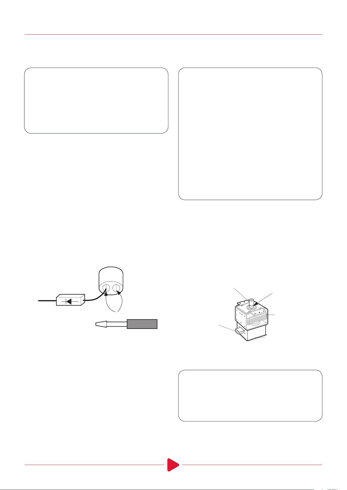
• A high voltage of approximately 2100 volts AC
is generated in the secondary of the high
voltage transformer which is increased by the
action of the high voltage diode and charging
of the high voltage capacitor.
• The negative 4,000 Volts DC is applied to the
lament of the magnetron.
When the oven is set at any level
except maximum
• The micom controller controls the ON-OFF
time of relay 2 by the applied signal to vary the
average output power of microwave oven as
POWER LEVEL (refer to page X).
When the door is opened during
cooking
• Both the primary switch and relay 2 are cut o
primary winding voltage of the high voltage
transformer.
• ON-OFF of relay 2 is coupled electrically with
opening and closing of the secondary switch.
• When the door is opened, the secondary switch
is opened and when the door is closed, the
secondary switch is closed.
• The cooking time stops counting down.
• Relay stops functioning.
• As the door is opened, if the contact of primary
switch and relay 2 and/or secondary switch fails
to open, the fuse opens due to the large current
surge caused by the monitor switch activation,
which in turn stops magnetron oscillation.
L
FUSE
TRANS-
FORMER
RELAY2
MICOMCONTROLLER
SECONDARY
SWITCH
SWITCH
N
MONITOR
SWITCH
PRIMARY
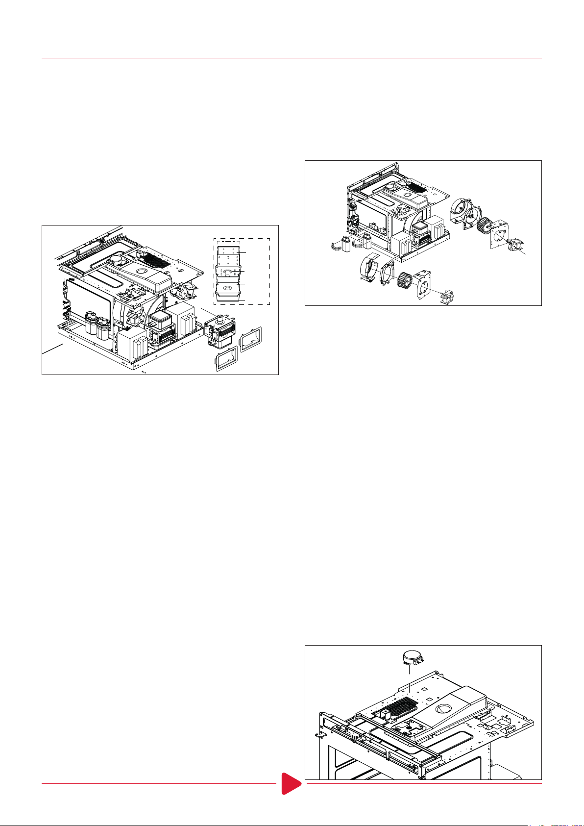
• The fan motor rotates and cools the
magnetron by blowing the air (coming from
the intake on the baseplate)
• The air is also directed into the oven to
exhaust the vapour in the oven through the
upper plate.
• Cooking time starts counting down.
• 3.2 volts AC is generated from the lament
MONITOR
SWITCH
L
FUSE
RELAY2
MICOMCONTROLLER
SECONDARY
SWITCH
PRIMARY
SWITCH
N
TRANS-
FORMER

6
Microwave service manual – Model: microMD UK
Service information
Tools and measuring instruments
Necessary tools
Tools normally used for TV servicing are sucient.
Standard tools are listed below.
• Diagonal pliers
• Long nose pliers
• Phillips screwdriver
• Flat blade screwdriver
• Wrench (size 5mm)
• Nutdriver (size 5mm)
• Adjustable wrench
• Soldering iron
• Solder
• Vinyl insulation tape
• Polishing cloth
Necessary measuring instruments
• TESTER (VOLTS-DC, AC., Ohmmeter)
• Microwave survey meter
- Holaday HI-1500, HI-1501
- Narda 8100, 8200
• Inch scale
• 600 cc non conductive material beaker
(glass or plastic), inside diameter:
approx. 8.5 cm(31/2 in.)
• Cylindrical and made of borosilicate glass vessel.
max. thickness: 3 mm
outside diameter: approx. 190mm
height: approx. 90mm
• Glass thermometer: 100°C or 212°F (1 deg scale)
Microwave leakage test
Cautions
• Be sure to check microwave leakage prior to
servicing the oven if the oven is operative prior
to servicing.
• The service personnel should inform the
manufacture importer, or assembler of any
certied oven unit found to have a microwave
emission level in excess of 5 mW/cm2and
should repair any unit found to have excessive
emission levels at no cost to the owner and
should ascertain the cause of the excessive
leakage. The service personnel should instruct
the owner not to use the unit until the oven
has been brought into compliance.
• If the oven operates with the door open, the
service personnel should:
- Tell the user not to operate the oven.
- Contact the manufacturer.
• The service personnel should check all surface
and vent openings for microwave leakage.
• Check for microwave leakage after every
servicing. The power density of the microwave
radiation leakage emitted by the microwave
oven should not exceed 4 mW/cm2. Always start
measuring of an unknown eld to assure safety
for operating personnel from radiation leakage.
Measuring microwave energy leakage
• Pour 275±15cc of 20±5°C(68±9°F) water in a
beaker which is graduated to 600 cc, and place
the beaker on the centre of the turntable.
• Set the energy leakage monitor to 2450
MHz and use it following the manufacturer’s
recommended test procedure to assure correct
result.
• When measuring the leakage, always use the 2-
inch (5cm) spacer supplied with the probe.
• Operate the oven at its maximum output.
• Measure the microwave radiation using an
electromagnetic radiation monitor by holding
the probe perpendicular to the surface being
measured.
Move probe along shaded area
Probe scanning speed
Less than 2.5 cm/sec
(1in/sec)

7
Microwave service manual – Model: microMD UK
Measurement with outer case
removed
• When you replace the magnetron, measure
for microwave energy leakage before the
outer case is installed and after all necessary
components are replaced or adjusted.
Special care should be taken in measuring the
following parts.
(Circled area of below Fig.)
- Around the magnetron
- The waveguide
Warning: Avoid
contacting any high
voltage parts
Measurement with a fully
assembled oven
• After all components, including the outer case,
are fully assembled, measure for microwave
energy leakage around the door viewing window,
the exhaust opening, and air inlet openings.
• Microwave energy leakage must not exceed the
values prescribed below.
Note: Leakage with the outer case removed
less than 5 mW/cm2.sq. Leakage for a fully
assembled oven (Before the latch switch (primary)
is interrupted) with the door in a slightly opened
position-less than 2 mW/cm2.sq.
Notes when measuring
• Do not exceed meter full scale deection.
• The test probe must be removed no faster than
1 inch/sec (2.5 cm/sec) along the shaded area,
otherwise a false reading may result.
• The test probe must be held with the grip
portion of the handle.
A false reading may result if the operator’s hand
is between the handle and the probe.
• When testing near a corner of the door, keep
the probe perpendicular to the surface, making
sure the probe is horizontal to the oven surface,
this may possibly cause probe damage.
Record keeping and notication
after measurement
After adjustment and repair of any microwave
energy interruption or microwave energy blocking
device, record the measured values for future
reference. Also enter the information on the
service invoice.
The microwave energy leakage should not be
more than 4 mW/cm after determining that all
parts are in good condition, functioning properly
and genuine replacement parts which are listed in
this manual have been used.
At least once a year, have the electromagnetic
energy leakage monitor checked for calibration
by its manufacturer.

8
Microwave service manual – Model: microMD UK
Measurement of microwave power output
• Microwave power output measurement is made
with the microwave oven supplied at its rated
voltage and operated at its maximum microwave
power setting with a load of (1000±5) g of potable
water.
• The water is contained in a cylindrical borosilicate
glass vessel having a maximum material
thickness of 3mm and an outside diameter of
approximately 190mm.
• The oven and the empty vessel are at ambient
temperature prior to the start of the test.
• The initial temperature (T1) of the water is
(10±2)°C. It is measured immediately before the
water is added to the vessel. After addition of
the water to the vessel, the load is immediately
placed on the centre of the turntable which is in
the lowest position and the microwave power
switched on.
• The time T for the temperature of the water
to rise by a value Δ T of (10±2)°K is measured,
where T is the time in seconds and ΔT is the
temperature rise. The initial and nal water
temperatures are selected so that the maximum
dierence between the nal water temperature
and the ambient temperature is 5°K.
• The microwave power output P in watts is
calculated from the following formula:
(I think there is some copy missing here!)
is measured while the microwave generator is
operating at full power. Magnetron lament
heat-up time is not included (about 3 sec).
• The water is stirred to equalize temperature
throughout the vessel, prior to measuring the
nal water temperature.
• Stirring devices and measuring instruments
are selected in order to minimize addition or
removal of heat.
Notes: For simple tests of microwave power
output, conduct it by heating one litre of water for
one minute, minimum temperature rise should be
6°C
P =
4187 x (ΔT) + 0.55 X (T2- T0) X M
T
• T2: Temperature after heating
• T0: Temperature of bowl
• M: Weight of bowl
WATER LOAD
TURNTABLE
Disassembly and adjustment
1. Outer case removal
1) Disconnect the power supply cord from the
outlet.
2) Remove the screws from the rear and along side
edges of the case.
The outer case must be moved backward to be
lifted o.

9
Microwave service manual – Model: microMD UK
3. Control panel assembly
1) Disconnect the wire and move out the lter
ASS’Y.
2) Disconnect the wire and take out the power
board.
3) Loose screws on both sides and take out the
control panel ASS’Y.
2. Power supply cord
1) Remove the outer case.
2) Disconnect two terminals, and remove one
screw of the earth terminal.
Caution: Discharge the high voltage
capacitor before servicing
4. Door assembly removal
1) Open the door.
2) Remove the gasket.
Caution: Be careful not to break the gasket
3) Lift up and take out the door.
Notes:
1. After replacing the door, be sure to check
that the primary switch, monitor switch, and
secondary switch operate normally.
2. After replacing the door, check for microwave
energy leakage with a survey meter. Microwave
energy must be below the limit of 5mW/cm2
(with a 275ml water load)
3. When mounting the door assembly to the oven
assembly, be sure to adjust the door assembly
parallel to the chassis. Also adjust so the door
has no play between the inner door surface and
oven frame assembly. If the door assembly is not
mounted properly, microwaves may leak from
the clearance between the door and the oven.
5. Air guide assembly removal
1) Disconnect the wire from lamp, release the
screws xed between air guides and magnetron.
2) Take out the lamp and the air guides.

10
Microwave service manual – Model: microMD UK
6. Magnetron removal
1) Disconnect the leadwire from the high voltage
transformer and high voltage capacitor.
2) Remove the air guide.
3) Carefully remove the mounting screws holding
the magnetron and the waveguide.
4) Remove the magnetron until the tube is clear
from the waveguide.
7. Fan assembly removal
1) Release the screws and take out the fan
assembly.
2) Separate the fan motor, fan guide and fan.
8. High voltage capacitor and diode
removal
1) Discharge the high voltage capacitor.
2) Disconnect the leadwire from fan motor, noise
lter and high voltage capacitor.
3) Remove the screw holding the Orice ASS’Y to
the oven cavity and remove the high voltage
diode earth screw.
3) Remove the screw holding the capacitor
bracket.
9. Removing the turntable motor
1) Disconnect the wire and remove the turntable
motor on the top of the cavity.
2) Turn the whole unit over 90 degrees. Loose
screw and remove the bottom cover.
3) Disconnect the wire and take out the turntable
motor.
4) After replacing the motor, x the cover back to
the base plate.
Waveguide
Magnetron
Gasket
Magnetron
Dome
Waveguide
Bracket
.
Note:
1) When removing the magnetron, make sure its
dome does not hit any adjacent parts, or it may
be damaged.
2) When replacing the magnetron, be sure to
install the magnetron gasket in the correct
position and be sure that the gasket is in good
condition.
3) After replacing the magnetron, check for
microwave leakage with a survey meter around
the magnetron. Microwave energy must be
below the limit of 5mW/cm2. (With a 275ml.
water load). Make sure that gasket is rigidly
attached to the magnetron. To prevent
microwave leakage, tighten the mounting
screws properly, making sure there is no gap
between the waveguide and the magnetron.

11
Microwave service manual – Model: microMD UK
Remove the screws on both side. Take out the
whole baseplate assemble.
12. Stirrer assembly removal
Remove the second magnetron rst.
10. High voltage transformer removal
1) Discharge the high voltage capacitor.
2) Disconnect the leadwire from magnetron, high
voltage transformer, and capacitor.
3) Remove the screw holding the high voltage
transformer to the baseplate.
1) The inner cover needs to be removed to repair
the bottom stirrer assembly.
2) The inner cover is xed in the cavity by glue.
Once it was removed, it needs to be glued again.
(It is not recommend to do this).
3) Take out the top cover inside the cavity to repair
the top stirrer assembly.
INNER COVER
Number 11 is missing!)

12
Microwave service manual – Model: microMD UK
13. Interlock system
1) Interlock mechanism
The door lock mechanism is a device which
has been specially designed to eliminate
completely, microwave activity when the door is
opened during cooking and thus to prevent the
danger resulting from the microwave leakage.
2) Mounting of the primary / monitor /
secondary switches to the latch board
3) Installation and adjustment of the latch
board to the oven assembly
• Mount the latch board to the oven assembly.
• Adjust the latch board in the arrow direction so
that oven door will not have any play in it when
the door is closed.
• Tighten the mounting screw.
•Check for play in the door by pushing the
door release button. Door movement should
be less than 0.5mm (1/64 inch).
Don’t push the door release button while
making adjustments. Make sure that the
latch moves smoothly after adjustments are
completed and that the screws are tight. Make
sure the primary, monitor, and secondary
switches operate properly by following the
continuity test procedure.
ADJUSTMENT
DIRECTION
PRIMARY
SWITCH
MONITOR
SWITCH
SECONDARY
SWITCH

13
Microwave service manual – Model: microMD UK
Interlock continuity test
1. Primary interlock switch test
When the door release button is depressed
slowly with the door closed, an audible
click should be heard at the same time or
successively at intervals. When the button is
released slowly, the latches should activate the
switches with an audible click.
If the latches do not activate the switches when
the door is closed, the switches should be a
adjusted in accordance with the adjustment
procedure. Disconnect the wire lead from the
primary switch. Connect the ohmmeter leads
to the common (COM) and normally open
(NO) terminal of the switch. The meter should
indicate an open circuit in the door open
condition. When the door is closed, the meter
should indicate a closed circuit.
When the primary switch operation is
abnormal, make the necessary adjustment or
replace the switch only with the same type of
switch.
2. Secondary interlock switch test
Disconnect the wire lead from the secondary
switch.
Connect the ohmmeter leads to the common
(COM) and normally open (NO) terminals of
the switch. The meter should indicate a open
circuit in the door open condition. When the
door is closed, meter should indicate a closed
circuit. When the secondary switch operation is
abnormal, make the necessary adjustment or
replace the switch only with the same type of
switch.
3. Monitor switch test
Disconnect the wire lead from the monitor
switch. Connect the ohmmeter leads to the
common (COM) and normally closed (NC)
terminals of the switch. The meter should
indicate closed circuit in the door open
condition. When the door is closed, meter
should indicate an open circuit. When the
monitor switch operation is abnormal, replace
with the same type of switch.
Note: After repairing the door or the interlock
system, it is necessary to do this continuity test
before operating the oven.
Warning: For continued protection against excessive
radiation emission, replace only with identical
replacement parts. Type No. KW3A for switches
Components Test procedure Results
Switches
(Wire leads removed)
Check for continuity of the
switch with an Ohm-meter
Door
open
Door
closed
Primary
switch
Type no.KW3A
Monitor
switch
Type no.KW3A
Secondary
switch
Type no.KW3A
Note: After checking for the continuity of switches,
make sure that are correctly connected.
COM
NO
COM
NC
COM
NO

14
Microwave service manual – Model: microMD UK
Components test procedure
Cautions:
1. Disconnect the power supply cord from the outlet whenever removing the outer
case from the unit. Proceed with the test only after discharging the high voltage
capacitor and removing the wire leads from the primary winding of the high voltage
transformer. (See page x-x)
2. All operational checks with microwave energy must be done with a load (1 litre of
water in container) in the oven.
Components Test procedure Results
High voltage transformer
(Wire leads removed)
1. Measure the resistance.
(Ohm-meter scale: Rx1)
• Primary winding
• Secondary
• Filament winding
2. Measure the resistance.
(Ohm-meter scale: Rx1000)
• Primary winding to ground
• Filament winding to ground
Approx: 1.4 ohm
Approx: 90 ohm
Less than: 1 ohm
Normal: Innite
Normal: Innite
Magnetron
(Wire leads removed) 1. Measure the resistance.
(Ohm-meter scale: Rx1)
• Filament terminal
2. Measure the resistance.
(Ohm-meter scale: Rx1000)
• Filament to chassis
Normal: Less than 1 ohm
Normal: Innite
PRIMARY
TERMINAL
SECONDARY
WINDING
FILAMENT
WINDING
TERMINAL

15
Microwave service manual – Model: microMD UK
Components Test procedure Results
Note: When testing the magnetron, be sure to install the magnetron gasket
in the correct position and be sure that the gasket is in good condition.
High voltage capacitor Measure the resistance.
(Ohm-meter scale: Rx1000)
• Terminal to terminal
Normal: Momentarily
indicates several ohms,
and then gradually
returns to 10M ohms
Measure the resistance.
(Ohm-meter scale: Rx1000)
• Terminal to case
Normal: ∞
High voltage diode
Note: Some inexpensive
meters may indicate innite
resistance in both direction.
Measure the continuity (Forward)
(Ohm-meter scale: Rx10000)
Normal: Continuity
Abnormal: ∞ *
Measure the continuity (Reverse)
(Ohm-meter scale: Rx10000)
Normal: ∞
Abnormal: Continuity
Antenna
Gasket
Chassis
Filament

16
Microwave service manual – Model: microMD UK
Components Test procedure Results
Fuse Check for continuity of the fuse with a
multi-meter. Normal Abnormal
Note: If the fuse is blown, check the primary, the secondary, and the
monitor switches, H.V.D. and H.V.C. before replacing the fuse. If the fuse
is blown by improper switch operation replace the defective switch and
the fuse at the same time. Replace just the fuse if the switches operate
normally.
Thermal cut-out Below
specied
temperature
Above
specied
temperature
L.V.Transformer of P.C.B
(Refer to schematic diagram)
Check for P.C.B. connector.
* Disconnect the 3 pin
connector from P.C.B.
Normal Abnormal
Relay 2, relay 3 of P.C.B.
(Wire leads removed)
Note: Relay
Relay 1: Fan motor
Turntable motor
Oven lamp
Relay 2: Microwave
Cooking
Start OFF
13 5
Relay2
Relay1

17
Microwave service manual – Model: microMD UK
Components Test procedure Results
Fan motor
(Wire leads removed)
Measure the resistance.
(Ohm-meter scale: Rx1)
Normal: 100 ~ 500 Ω
Abnormal: ∞ or several Ω
Turntable motor
(Wire leads removed)
Measure the resistance.
(Ohm-meter scale: Rx1000)
Normal:
Approx.100 ~ 200K Ω
Abnormal: ∞ or several Ω
Notes:
• A microwave leakage test must always be performed when the unit is serviced for any reason.
• Make sure the wire leads are in the correct position.
• When removing the wire leads from the parts, be sure to grasp the connector, not the wires.

18
Microwave service manual – Model: microMD UK
Trouble shooting
If you receive a complaint from your customer, evaluate the complaint carefully. If the following
symptoms apply, please instruct the customer in the proper use of the microwave oven. This can
eliminate an unnecessary service call.
Cautions:
1. Check grounding before checking for trouble.
2. Be careful of the high voltage circuit.
3. Discharge the high voltage capacitor. (See page X-X)
4. When checking the continuity of the switches or of the high voltage transformer,
disconnect one lead wire from these parts and then check continuity with the AC plug
removed. To do otherwise may result in a false reading or damage to your meter.
5. Do not touch any part of the circuitry on the digital programmer circuit since static
electric discharge may damage this control panel.
Always earth yourself while working on this panel to discharge any static charge built
up in your body.
Condition Cause Remedy
Inserting many plugs into one
plug outlet and using them at the
same time (causes overloading).
Using metallic ware and
allowing it to touch the oven
wall.
Inconsistent intensity
of microwave by their
characteristics.
Microwave oven plug is not
inserted tightly.
Ceramic ware trimmed in gold
or silver powder is used.
Insert microwave oven plug
securely.
Avoid using other electrical
appliances when you use the
microwave oven.
Do not use metallic ware for
cooking except where noted in
the cooking guide.
1. Wrap the thinner part with
aluminium foil.
2. Use plastic wrap or lid.
3. Stir once or twice while
cooking soup, cocoa or
milk, etc.
Do not use any type of cookware
with metallic trimming.
Microwave oven does not work.
Sparks occurring.
Uneven cooking.
Output power is too low. Low AC input voltage.
Food temperature is too low.
Use the microwave oven at
adequate line voltage.
This may not be a defect. It is
possible that the food should
be cooked for a longer time
period.

19
Microwave service manual – Model: microMD UK
(Trouble 1)
The following visual conditions indicate a probable defective control circuit.
Condition Check Result Cause Remedy
1. No input can be
programmed.
2. Some inputs
cannot be
programmed.
Replace key
membrane
assembly and check
operation.
3. Display shows a
number or gure
dierent from
one touched.
4. Random
programming
when touching
other pads.
5. Display is xed
at some gure
and can not
accept any
input.
Defective key
membrane
assembly.
Replace key
membrane
assembly.
Continuity.
Check the
connection between
membrane key
assembly and PCB
assembly.
Still have trouble.
No continuity.
Everything works as
specied.
Defective PCB
assembly.
Defective PCB
assembly.
Loose connection.
Replace PCB
assembly.
Replace PCB
assembly.
Connect them
tightly.
1. Incomplete segments.
• Segment missing.
• Partial segment missing.
• Digit ickering (NOTE: Slight ickering is normal.)
2. Colon does not turn on or blink.
3. A distinct change in the brightness of one or more numbers in display.
4. One or more digits in the display are not lighting.
5. Display indicates a number dierent from one touched, for example, key in 5 and 3 appears
in the display.
6. Specic numbers (for example 7 or 9) will not display when key pad is touched.
7. Display does not count down with time blinking or up with clock operation.
8. Display obviously jumps in time while counting down.
9. Display counts down too fast while cooking.
10. Each indicator light does not turn on after setting cooking cycle.
11. Display time of day does not reappear when cooking is nished.
12. Beep sound is not heard when correct key is touched.

20
Microwave service manual – Model: microMD UK
(Trouble 2)
Oven does not operate at all; display window does not display any gures and
no input is accepted.
Condition Check Result Cause Remedy
1. Fuse blows.
1. Fuse is not
tipping.
Check continuity
of primary switch
(with door opened).
Replace fuse
Disconnect one
side of the wire
lead connected
from transformer
to the high voltage
capacitor and
operate the unit.
Shorted contact at
the primary switch.
Defective high
voltage capacitor.
Defective high
voltage transformer.
Replace primary and
monitor switches.
Replace high voltage
capacitor.
Replace high
voltage transformer.
Continuity.
OK.
No continuity.
Fuse blows again.
Continuity.
Normal.
Check continuity
of monitor switch
(with door closed).
Check latch and
hook when door
closed.
No continuity.
Not OK.
Malfunction of the
monitor switch.
Main PCB defective.
Latch board back o.
Replace primary and
monitor switches.
Replace PCB.
Forward latch board.
Note: All these switches must be replaced at the same time. Refer to page X-X, X-X
Other manuals for Merrychef microMD UK
1
Table of contents
Other Welbilt Microwave Oven manuals