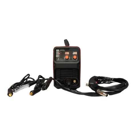
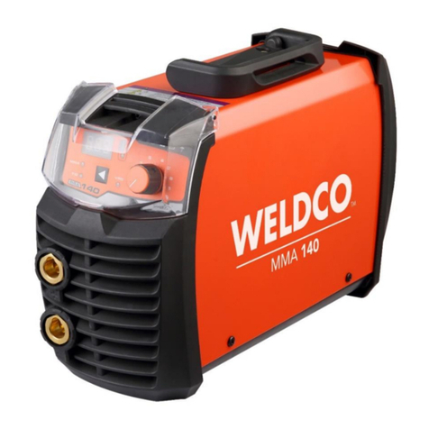
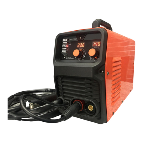
WELDCO MMA180 User manual

MMA180
Inverter Arc Welder
OPERATORS MANUAL
IMPORTANT:
This manual contains important information regarding safety, operation, maintenance and storage of this product.
Before use read carefully and understand all cautions, warnings, instructions and product labels. Failure to do so
could result in serious personal injury and/or property damage.

2
TABLE OF CONTENTS
Thank You For your Purchase..................................................................................................................................................... 3
Unpacking Your New Welder ......................................................................................................................................................... 3
Welding Hazards and Safety....................................................................................................................................................... 4
Work Area ...................................................................................................................................................................................... 4
Personal Protective Equipment and Clothing (PPE) ....................................................................................................................... 4
Electromagnetic and Radio Frequencies –“PACEMAKERS”........................................................................................................... 5
Pre-Checks...................................................................................................................................................................................... 5
Warning.......................................................................................................................................................................................... 5
Storage and Transportation ........................................................................................................................................................... 5
Technical Description ................................................................................................................................................................. 6
Compliance Plate............................................................................................................................................................................ 6
Duty Cycle....................................................................................................................................................................................... 6
Input Plug ....................................................................................................................................................................................... 6
Operating Environment.................................................................................................................................................................. 6
Machine Layout ......................................................................................................................................................................... 7
MMA (Stick) Welding Setup ....................................................................................................................................................... 8
DC Lift TIG Welding Setup ........................................................................................................................................................ 10
Maintenance............................................................................................................................................................................ 12
Warranty.................................................................................................................................................................................. 12
Troubleshooting....................................................................................................................................................................... 13
Notes ....................................................................................................................................................................................... 14

3
Thank you for your Purchase.
Weldco would like to thank you for purchasing the MMA180 Inverter Welder.
This manual is designed to guide you through using your new machine.
Your Weldco inverter welder utilizes the latest in welding technology to ensure you receive professional results in a
variety of applications.
UNPACKING YOUR WELDER
Contents:
•MMA inverter power source.
•Carry strap for power source.
•3m Heavy Duty Earth Clamp and Lead.
•4m Heavy Duty Twist lock electrode holder and Lead.
•Manual
Please check all contents are correct and damage free before first use, if any issues please contact your local
dealer.

4
WELDING HAZARDS AND SAFETY
Welding poses a variety of hazards to health and safety. Please ensure you have correct safety equipment for yourself and those
within the welding area. Your local distributor will be able to assist you with the correct Weldco protective helmet and gloves.
Detailed documents can be located on the Worksafe website, www.worksafe.govt.nz, topic welding.
WORK AREA
•Ensure your work area is clear, dry and free of trip hazards.
•That the area is well ventilated, and all flammable materials are removed to a safe distance.
•Never leave your welder powered up – unattended.
FIRE RISK
•Due to the welding process producing molten metal including sparks and fumes maximum fire safety must always
be obeyed. Ensure you have direct access to the correct fire extinguisher for your environment.
•Never weld tanks or containers that have or have held flammable liquid, gas or where the contents are under
pressure. This should only be carried out by trained specialists.
•Ensure that the area is checked for smoldering materials as material will remain hot well after welding.
ELECTRICITY CAN KILL
•Never weld or attempt to weld in a wet or raining environments. There is a serious risk of electrocution to the
operator or those within the area.
•it is recommended that the welder be connected to an RCD.
FUMES AND GASES
•Welding produces fumes and gases that can be harmful to the operator and those within the surrounding areas.
Always ensure that there is plenty of ventilation and fresh air.
•Do not weld material that has been coated or contaminated with paint, varnish or rubber as they may give off
harmful fumes or gas and increase the risk of fire and or explosion.
PERSONAL PROTECTIVE EQUIPMENT AND CLOTHING
The user must comply with occupational health and safety rules and wear appropriate protective equipment.
BURNS
•The welding process causes the work piece and surrounding items to become hot.
•It is always recommended that flame resistant clothing be warn.
•Welding gloves must be worn to help prevent burns to hands and arms when handling hot objects.
•Avoid skin exposure to the Ultraviolet rays produced by the arc. It is recommended that skin be protected from
these harmful rays. Serious burns are possible when this recommendation is not followed.
•Approved welding helmets must be worn by the operator and any personnel with in 10m of the work area. It is also
recommended that welding safety screens are installed to protect.
•It is always recommended that enclosed footwear with rubber soles be worn to protect from sparks and molten
metal and to reduce the risk of electrocution.
•As welding produces gases and fumes many of these can be harmful it is recommended that the operator and
these in the direct area wear respirators with the relevant protection.
•Always where safety glasses when chipping the slag, scraping or preparing the work piece.

5
ELECTROMAGNETIC AND RADIO FREQUENCIES – “PACEMAKERS”
•Avoid contact with the energized work piece.
•Always ensure you have adequate protection from electrocution and burns.
•Since the welder owns strong electromagnetic and radio frequencies. Persons fitted with “PACEMAKERS” or similar
devices MUST consult their doctor before turning on the welder. This relates to both the operator and those
nearby.
PRE-CHECKS
The following items must be checked by the operator each time before powering up the power source.
•Ensure that the welder is damage free and no exposed wires.
•Check all welding cables, insulation and accessories are free of damage.
•The work area is checked and free of hazards
•All personal protective clothing and equipment is defect free.
•Access to Fire extinguisher and welding blanket.
•All flammable material has been removed.
WARNING!
•Disconnect the power source before servicing and ensure the device has powered down.
•Contact your dealer or reseller immediately should your welder require servicing.
•It is not recommended that you remove the covers to carry out your own servicing – doing so will void the
warranty.
STORAGE, TRANSPORTATION AND MAINTENANCE
•Your welder contains sensitive electronics and needs to be stored in a dust and moisture free environment.
•Periodically your welder should be blown down using dry compressed air to remove any dust and metal fillings.
•Once your power source and welder have cooled down. Remove your accessories for storage – wipe both the welder
and accessories down with a clean cloth to remove any contaminates.
•Store your welder in a dry safe environment.
•When transporting ensure that the power source, accessories and wire are secure.
•Cylinders need to be stored and transported as per NZ regulations and safe operating procedures.

6
TECHNICAL DESCRIPTION
COMPLIANCE PLATE
Duty Cycle
The welder’s duty cycle is the number of minutes in a 10-minute period the power source can safety produce
the set welding current (actual arc on). If this is exceeded the machine will enter thermal overload, turning the
welding current off protecting the welder. This is indicated by the light on the front panel.
For example:
•At 139 amps the welder will ARC continuously for 6 mins and needs to rest for 4 mins.
•At 70 amps the welder will ARC continuously or 100% of the time.
The duty cycle is tested at 40 degrees celsius, if the welder is operating in lower temperature e.g. 20 degrees
celsius the duty cycle will be higher.
INPUT PLUG
The MMA180 is fitted with a 15amp plug. This machine is designed to work with 15amp wall sockets. It is important
that the machine is plugged directly into the mains plug. If an extension cord must be used a minimum 2.5mm wire
thickness is require and no more than 10m.
Using unsuitable extension cords will reduce the input voltage (known as voltage drop) and this will void the
warranty of your machine.
Any modification to the 15amp plug on this welder will void warranty.
OPERATING ENVIRONMENT
•Operating temperature: -10℃~40℃.
•Transportation and storage: -25℃~55℃.
•Relative air humidity: 40℃ ≤ 50%; 20℃ ≤ 90%.
•The dust, acids, corrosive gases and substance in the ambient air must be not higher than normal level.
•Altitude must be less than 1km.
•Good ventilation around the machine, at a distance of at least 50cm around.
•Power source must be kept on a level surface to reduce the risk of the machine falling.

7
MACHINE LAYOUT
Front
Rear
10. 15amp 230volt Input Plug
11. ON OFF Switch
5.
7..
1. Amperage Adjustment Dial
2. Thermal Overload light
3. Amperage Display
4. Welding Type Selector
5. Positive Terminal
6. Negative Terminal
7. ARC MMA Indicator Light
8. Lift TIG Indicator Light
9. VRD Indicator
9.
2.
3.
1.
6.
8.
4.
10.
11.

8
SET UP FOR MMA (STICK) WELDING.
Please ensure you have all relevant safety equipment and PPE ready.
This setup is for the most common electrode positive setting for General purpose rods. Please check your electrode
packaging to confirm.
1. Connect the Earth clamp cable into the NEGATIVE terminal on the front of the machine. Connect the Earth
clamp to the work piece. It is important the earth clamp makes strong contact with bare metal – remove
paint, rust or other contaminates to ensure strong contact. Failure to do so will reduce your welding
performance.
2. Connect the Electrode Holder cable into the POSITIVE terminal on the front of the machine.
Ensure that the plug is secure in the socket to reduce any chance of arcing from loose connection
3. Ensure the main power switch (11) is in the OFF position. Plug the 15amp plug into the 15amp wall socket.
Turn power to the ON position on both the wall socket and the power source. The front panel will illuminate,
and the cooling fan will start.

9
4. Once the machine has powered up the default setting is for MMA if the MMA light is not on press the
welding type selector (4) to select MMA.
5. Your Weldco Inverter welder is fitted with a “Voltage Reduction Device” (VRD). The VRD reduces the open
circuit voltage to safer levels. The VRD default is OFF. To activate this feature press and hold the welding
process button (4) for 3-5 second until the VRD light is activated. Press and hold the button again to turn OFF
VRD.
6. Adjust the welding current to the relevant level for the welding electrode type and size, as per the electrode
manufacture, by adjusting the current selection dial (1).
7. Insert the electrode into the Twistlock electrode holder and tighten firmly. Once the electrode contacts the
work piece (also any metal connected to the work piece) the electrode will strike an arc, for this reason do
not rest the fitted electrode on the work area.
8. With you PPE on, Strike the work piece with the electrode (like striking a match) hold the electrode slightly
off the work piece to maintain a constant arc.
9. To stop the weld quickly lift the electrode from the work piece (stopping the electrical circuit).
10. It is important to chip away the “SLAG” before adding continuing to weld and for weld inspection – allowing
the weld to cool slightly will make “SLAG” removal easier.
1.
3.
2.
9.
4.
8.

10
SET UP FOR DC LIFT TIG WELDING.
Optional accessories required.
This machine is designed to weld Mild steel and Stainless steel only.
To weld Aluminum AC current is required.
Please ensure you have all relevant safety equipment and PPE ready.
1. Connect l the Earth clamp cable into the POSITIVE terminal on the front of the machine. Connect the Earth
clamp to the work piece. It is important the earth clamp makes strong contact with bare metal –remove
paint, rust or other contaminates to ensure strong contact. Failure to do so will reduce your welding
performance.
2. Connect the Optional Weldco VALVE Tig Torch (WDC0818) into the NEGATIVE terminal on the front of the
machine.
Ensure that the plug is secure in the socket to reduce any chance of arcing from loose connection
3. Connect the Optional Weldco Argon Regulator (WDC0812) to the argon cylinder and connect the gas line
from the Tig torch to the regulator. With the valve of the TIG torch open turn on the argon cylinder and set
the regulator to between 6-10 L/min. Close the valve on the TIG torch.
It is good practice to test for leaks. Close the cylinder valve. If there are no leaks the regulator will
maintain the set L/min and cylinder pressure. Always turn off your cylinder valve when not in use.
4. Ensure the main power switch (11) is in the OFF position. Plug the 15amp plug into the 15amp wall socket.
Turn power to the ON position on both the wall socket and the power source. The front panel will
illuminate, and the cooling fan will start.

11
5. Once the machine has powered up the default setting is for MMA press the welding type selector (4) to
select TIG.
6. Your Weldco Inverter welder is fitted with a “Voltage Reduction Device” (VRD). The VRD is not used for TIG
welding.
7. Adjust the welding current (1) to the relevant level for the Tungsten size and material.
8. Open the valve on the argon cylinder
9. Open the valve on the TIG torch gas will flow.
10. With your welding helmet and PPE on, rest your ceramic cup on the work piece roll your hand holding the
torch so the tungsten makes contact with the work piece, roll you hand back to lift the tungsten off your
torch to maintain a 2-4mm gap from the workpiece (this is called rocking the cup) . The welder will send
pulse to start the welding current once the electrical field in detected.
11. To stop the weld quickly lift the TIG torch from the work piece (stopping the electrical circuit).
12. Once you have finished welding or if you need to reposition the work piece CLOSE the valve on the TIG
Torch to save gas. Do not rest the torch on the workpiece or connected metal or the tungsten will spark.
13. CLOSE the cylinder valve and turn OFF your machine.
WARNING!
PLEASE CHECK YOUR ARGON CYLINDER VALVE IS CLOSED AFTER USE.
4.
2.
1.
7.
3.

12
MAINTENANCE
•The major difference between an inverter arc welder and traditional welder is the inverter welder has a lot
of advanced electronic components. Repair of this product can only be carried out by Approved Weldco
Technicians.
•As part of general use, the user must carry out all pre-checks and ensure that the welder is maintained.
Where the machine is in contact with dust or contaminants, these must be cleaned off regularly. In dusty
environments the power source will need to be blown down from time to time with dry compressed air at a
suitable level. The machine must not be plugged in when this happens, all care and responsibility must
always be maintained to those in the surrounding area.
•All accessories and leads must be inspected regularly by the user. Any repairs must be done by Approved
Weldco Technicians.
Warning!
Due to high voltage in the main circuit of the welder,
DO NOT remove the cover except for Approved
Weldco Technicians. Failure to do so could result in electrocution leading to injury or death.
WARRANTY
Your Weldco power source is covered by Weldco’s 24-month warranty covering faulty materials and manufacturing.
During this time should your Weldco power source fail please contact your authorized Weldco distributor.
This warranty does not cover freight or goods serviced by un-authorized personnel.
Weldco NZ will inspect your power source for faulty material or workmanship and will only be replaced if repair is
not possible.
Note: The warranty is for the power source only. Leads and accessories are consumables and only replaced for
failures due to materials and manufacture.

13
TROUBLESHOOTING
No.
Description
Possible Cause
Remedy
1
Abnormal indicator
Bad ventilation leads to
overheating protection
Improve ventilation conditions
High environmental
temperature
Automatic recovery after decreasing
Exceed rated duty cycle
Automatic recovery once machine has cooled to correct level
2
Current knob
broken
Potentiometer damaged
Replace.
3
Cooling fan not
working or low
rotational speed
Faulty power switch
Replace the switch
Faulty fan
Replace the fan
Led broken
Check the circuit
4
No open circuit
voltage
Overheating
See point 1
Faulty power switch
Replace the switch
5
Electrode holder
cable is too hot;
output terminals
are too hot.
Capacity on electrode holder
is too small
Replace larger capacity electrode holder
Cable is too thin
Replace a proper cable
Socket is loose
Remove the oxide coat and re-tight
6
Power off
Power capacity is not suitably
large enough for the welder
Increase capacity.
Check fuse.
7
Other problems
Contact reseller
Warning!
Protect the machine from rapid power switching. When the machines senses that the power is turned
on and off rapidly the unit will turn off. The power indicator light will not turn on. Allow the machine
to rest for a few minutes and normal operation should continue. If this does not rectify the issue,
please contact your approved WELDCO Technician.

14
NOTES:

15
NOTES:

16
WELDCO NEW ZEALAND
Christchurch 8024
New Zealand
www.weldco.co.nz
Made in China © 2021
Table of contents
Other WELDCO Welding System manuals
Popular Welding System manuals by other brands

Riland
Riland TIG 200 AC/DC operating manual

RODEX
RODEX RDX50160 instruction manual

Sumig
Sumig NANOCUT 40 operating manual

Miller Electric
Miller Electric Spoolmatic 15A owner's manual

ESAB
ESAB POWERCUT-1250 Installation, operation and service manual

Lincoln Electric
Lincoln Electric CLASSIC 11572 Operator's manual

Lincoln Electric
Lincoln Electric POWER WAVE POWER WAVE WELDING SYSTEMS brochure

Migatronic
Migatronic AUTOMIG PULSE user guide

Miller
Miller SGA 100 owner's manual

Lincoln Electric
Lincoln Electric SPEEDTEC 400S Operator's manual

Lincoln Electric
Lincoln Electric Invertec V155-S Service manual

TECNA
TECNA 3680 Use and maintenance manual