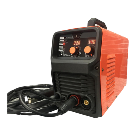
WELDCO WDC0821 User manual

WDC0821
Inverter ACDC TIG/MMA Welder
OPERATORS MANUAL
IMPORTANT: This manual contains important information regarding safety, operation, maintenance and storage of this
product. Before use read carefully and understand all cautions, warnings, instructions and product labels. Failure to do so
could result in serious personal injury and/or property damage.

TABLE OF CONTENTS
Thank You For your Purchase............................................................................................................................3
Unpacking Your New Welder.................................................................................................................................... 3
Welding Hazards and Safety .............................................................................................................................4
Work Area.................................................................................................................................................................4
Personal Protective Equipment and Clothing (PPE) .................................................................................................4
Electromagnetic and Radio Frequencies –“PACEMAKERS” .....................................................................................5
Pre-Checks ................................................................................................................................................................5
Warning..................................................................................................................................................................... 5
Storage and Transportation......................................................................................................................................5
Technical Description .......................................................................................................................................6
Compliance Plate ......................................................................................................................................................6
Duty Cycle .................................................................................................................................................................6
Input Plug..................................................................................................................................................................6
Operating Environment ............................................................................................................................................6
Machine Layout ...............................................................................................................................................7
Control Panel ............................................................................................................................................................8
TIG Torch Arc Starting.............................................................................................................................................12
Foot Control............................................................................................................................................................12
TIG Welding Setup.......................................................................................................................................... 13
TIG Welding Techniques .........................................................................................................................................15
Tungsten Electrodes................................................................................................................................................16
TIG Welding Trouble Shooting................................................................................................................................17
MMA (Stick) Welding Setup............................................................................................................................19
MMA Welding Trouble Shooting ............................................................................................................................21
Maintenance..................................................................................................................................................22
Warranty .......................................................................................................................................................22
Notes.............................................................................................................................................................23

THANK YOU FOR YOUR PURCHASE
Weldco would like to thank you for purchasing the Inverter AC DC TIG and MMA welder.
This manual is designed to guide you through using your new machine.
Your Weldco inverter welder utilizes the latest in welding technology to ensure you receive excellent results in a
variety of applications.
UNPACKING YOUR WELDER
Contents:
•Welding Power source.
•4m Variable amp TIG Torch.
•Earth clamp and lead.
•Twist style holder and lead.
•TIG torch consumables (not pictured).
Please check all contents are correct and damage free before first use, if any issues please contact your
local dealer.

WELDING HAZARDS AND SAFETY
Welding poses a variety of hazards to health and safety. Please ensure you have correct safety equipment for yourself and
those within the welding area. Your local distributor will be able to assist you with the correct Weldco protective helmet and
gloves. Detailed documents can be located on the Worksafe website, www.worksafe.govt.nz, topic welding.
WORK AREA
•Ensure your work area is clear, dry and free of trip hazards.
•That the area is well ventilated, and all flammable materials are removed to a safe distance.
•Never leave your welder powered up – unattended.
FIRE RISK
•Due to the welding process producing molten metal including sparks and fumes maximum fire safety must
always be obeyed. Ensure you have direct access to the correct fire extinguisher for your environment.
•Never weld tanks or containers that have or have held flammable liquid, gas or where the contents are under
pressure. This should only be carried out by trained specialists.
•Ensure that the area is checked for smoldering materials as material will remain hot well after welding.
ELECTRICITY CAN KILL
•Never weld or attempt to weld in a wet or raining environments. There is a serious risk of electrocution to the
operator or those within the area.
•it is recommended that the welder be connected to an RCD.
FUMES AND GASES
•Welding produces fumes and gases that can be harmful to the operator and those within the surrounding areas.
Always ensure that there is plenty of ventilation and fresh air.
•Do not weld material that has been coated or contaminated with paint, varnish or rubber as they may give off
harmful fumes or gas and increase the risk of fire and or explosion.
PERSONAL PROTECTIVE EQUIPMENT AND CLOTHING
The user must comply with occupational health and safety rules and wear appropriate protective equipment.
BURNS
•The welding process causes the work piece and surrounding items to become hot.
•It is always recommended that flame resistant clothing be warn.
•Welding gloves must be worn to help prevent burns to hands and arms when handling hot objects.
•Avoid skin exposure to the Ultraviolet rays produced by the arc. It is recommended that skin be protected from
these harmful rays. Serious burns are possible when this recommendation is not followed.
•Approved welding helmets must be worn by the operator and any personnel with in 10m of the work area. It is
also recommended that welding safety screens are installed to protect.
•It is always recommended that enclosed footwear with rubber soles be worn to protect from sparks and molten
metal and to reduce the risk of electrocution.
•As welding produces gases and fumes many of these can be harmful it is recommended that the operator and
these in the direct area wear respirators with the relevant protection.
•Always where safety glasses when chipping the slag, scraping or preparing the work piece.

ELECTROMAGNETIC AND RADIO FREQUENCIES – “PACEMAKERS”
•Avoid contact with the energized work piece.
•Always ensure you have adequate protection from electrocution and burns.
•Since the welder owns strong electromagnetic and radio frequencies. Persons fitted with “PACEMAKERS” or
similar devices MUST consult their doctor before turning on the welder. This relates to both the operator and
those nearby.
PRE-CHECKS
The following items must be checked by the operator each time before powering up the power source.
•Ensure that the welder is damage free and no exposed wires.
•Check all welding cables, insulation and accessories are free of damage.
•The work area is checked and free of hazards
•All personal protective clothing and equipment is defect free.
•Access to Fire extinguisher and welding blanket.
•All flammable material has been removed.
WARNING!
•Disconnect the power source before servicing and ensure the device has powered down.
•Contact your dealer or reseller immediately should your welder require servicing.
•It is not recommended that you remove the covers to carry out your own servicing – doing so will void the
warranty.
STORAGE, TRANSPORTATION AND MAINTENANCE
•Your welder contains sensitive electronics and needs to be stored in a dust and moisture free environment.
•Periodically your welder should be blown down using dry compressed air to remove any dust and metal fillings.
•Once your power source and welder have cooled down. Remove your accessories for storage – wipe both the
welder and accessories down with a clean cloth to remove any contaminates.
•Store your welder in a dry safe environment.
•When transporting ensure that the power source, accessories, and wire are secure.
•Cylinders need to be stored and transported as per NZ regulations and safe operating procedures.

TECHNICAL DESCRIPTION
COMPLIANCE PLATE
DUTY CYCLE
The welder’s duty cycle is the number of minutes in a 10-minute period the power source can safety produce the set
welding current (actual arc on). If this is exceeded the machine will enter thermal overload, turning the welding current
off protecting the welder. This is indicated by the light on the front panel. The fan will continue to cool the power source
during thermal overload.
For example:
•At 125 amps the welder will TIG weld continuously for 6 mins and needs to rest for 4 mins.
•At 100 amps the welder will TIG weld continuously or 100% of the time.
The duty cycle is tested at 40 degrees Celsius, if the welder is operating in lower temperature e.g. 20 degrees Celsius the
duty cycle will be higher.
INPUT PLUG
The TIG 200 ACDC is fitted with a 15amp plug. This machine is designed to work with 15amp wall sockets. It is important
that the machine is plugged directly into the mains plug. If an extension cord must be used a minimum 2.5mm wire
thickness is required and no more than 10m in length.
Using unsuitable extension cords will reduce the input voltage (known as voltage drop) and this will void the warranty of
your machine.
OPERATING ENVIRONMENT
•Operating temperature: -10℃~40℃.
•Transportation and storage: -25℃~55℃.
•Relative air humidity: 40℃ ≤ 50%; 20℃ ≤ 90%.
•The dust, acids, corrosive gases and substance in the ambient air must be not higher than normal level.
•Altitude must be less than 1km.
•Good ventilation around the machine, at a distance of at least 50cm around.
•Power source must be kept on a level surface to reduce the risk of the machine falling.

MACHINE LAYOUT
Front Panel
1. Control Panel
2. Outlet Gas Quick Connect Fitting
3. Torch/Foot Control Connector
4. Negative (-) Outlet Terminal
5. Positive (+) Outlet Connector
Rear Panel
6. Inlet Gas Quick Connect Fitting
7. Cooling Fan
8. Main Power Input Lead with 15-amp Plug.
9. ON/OFF Switch
7
2
4
3
5
6
9
8
1

CONTROL PANEL LAYOUT
Mode Selector
•MMA (ARC/Stick)
•TIG LIFT – TIG Lift ARC Starting (Contact)
•TIG HF – TIG High Frequency ARC Starting (non-contact)
Current Style
•AC – Alternating Current (Aluminium, Aluminium Alloys, Magnesium, Zinc)
•DC – Direct Current (Mild Steel, Stainless Steel, Copper, Titanium)
Torch Trigger Control
2T Trigger Control.
• Press the torch trigger and hold.
• The set pre-gas flows and the arc will start, upsloping to the set amperage.
• To finish the weld, release the trigger the amperage will begin to downslope at
the preset rate. If downslope set to zero, the arc will instantly stop.
4T Trigger Control.
• Press the torch trigger and hold.
• The set pre-gas flows and the arc will start. (Start Current).
• Release the trigger and the amperage will upslope to the preset amperage.
•To finish the weld, press and hold the trigger, the amperage will begin to downslope at
the preset rate and hold at the preset end current.
• Release the trigger again and the arc will stop, and the post flow will continue
for the preset time.

Multi-function control Knob
•Turn clockwise to increase or anti-clockwise to decrease the value
displayed on the LED display.
•Press down to step through the welding process menu.
LED Display and indicator lights
1. MMA (ARC) mode Hot Start Indicator: Adjustment percentage 0 – 100%, Increases current when striking arc
excellent for difficult to start electrodes
2. Welding Current
3. MMA (ARC) mode ARC Force Indicator: Adjustment 0 – 100% Lower ARC Force for softer smooth arc, Higher ARC
Force give aggressive digging ARC. Increases Current when the ARC is really tight.
4. Thermal Overload Indicator
5. Indicates when Voltage Displayed
6. Indicates when Amperage Displayed
7. Indicates when Hertz Displayed
8. Indicates when Percentage Displayed
9. Indicates when time in Seconds Displayed
1
3
2
9
8
7
6
5
4

1. Pre gas Timer: Time in seconds before the arc is ignited 0.0 – 2.0 Seconds
2. Start Current (Amps): (4T ONLY) Set current at the start of the weld DC 10 – 170, AC 10 – 200
3. Upslope Time: Sets the Time in seconds between Start Current and Welding Current 1.0 – 10 seconds
4. Welding Current: Sets the Welding Current (Peak Amperage) TIG DC 10 – 170, TIG AC 10 – 200, MMA 10 – 170
5. Downslope: time in seconds from Welding Current to End Current 0 – 10 seconds
6. End Current: (4T ONLY) Current (Amperage) at the finish of the weld TIG DC 10 – 170, TIG AC 10 – 200
7. Post gas Timer: Time in seconds the gas flows after the arc is out 0.1 – 10.0 Seconds
Pulse Settings
8. Pulse: OFF
9. Pulse: ON
10. Base Current: Current set for the base amperage of the pulse cycle TIG DC 10 – 170, TIG AC 10 – 200
11. Pulse Width: Percentage of time the Welding Current (Peak Welding Amperage) during each pulse cycle, eg 70%
Peak 30% Base Current. Adjustment 5 – 95%
12. Pulse Frequency: (HZ) Number of transitions Welding Current (Peak Welding Amperage) to Base Current 0.5 – 200
HZ
1
3
11
2
3
3
3
5
10
0
4
3
13
3
7
3
6
3
9
3
12
3
8
3

Alternating Current Balance (AC TIG welding only)
13. AC Balance: Adjusts the balance of the AC wave form – setting of 0 gives a 75% penetration / 25% Oxide cleaning
(75% Positive / 25% Negative).
Increasing the Positive (+) AC balance increases the cleaning time resulting in less weld penetration and more heat
towards the tungsten (better for older /contaminated alloys)
Increasing the Negative (-) AC Balance decreases the cleaning time resulting in more weld penetration and less heat
towards the tungsten (better for newer, cleaner alloys).
FRONT PANEL NUMBER
AC BALANCE (%)
DC BALANCE %
-5
13%
87%
-4
15%
85%
-3
17%
83%
-2
19%
81%
-1
21%
89%
0
25%
75%
1
30%
70%
2
34%
66%
3
38%
62%
4
42%
58%
5
45%
55%

TIG TORCH ARC STARTING
TIG Lift Arc Start.
TIG High Frequency Arc Start.
Foot Control.
•The optional Weldco 3m foot control take control a step further giving you
ultimate control over welding current (amperage).
•Parent/Child relationship between Welder and foot controller, means when you
set the Welding Current to 100 amps the foot controller maximum is 100amps, if
set to 50 amps the foot controller’s maximum is 50 amps.
2. Press the trigger on
the Tig torch.
3. Roll your hand holding the
torch so the tungsten touches
the work piece.
1. With your PPE on, rest
the ceramic cup on the work
piece with the tungsten
extending 1-2mm out of the
ceramic cup.
4. Roll your hand back to lift
the tungsten off the work
piece maintaining a 2-4mm
gap from the work piece This is
called rocking the cup). To
finish the weld, release the
Torch Trigger as per 2T/4T
mode.
1. With your PPE on, rest the
ceramic cup on the work
piece with the tungsten
extending 1-2mm out of the
ceramic cup.
2. Press and hold the
trigger on the Tig torch.
3. The arc will start across the gap between the tungsten and the work piece. Maintain
an even distance of about approx. 2 - 4mm between the work piece and the tungsten to
maintain the arc.
To finish the weld, release the Torch Trigger as per 2T/4T mode.

TIG WELDING SETUP
Please ensure you have all relevant safety equipment and PPE ready.
•Connect the Earth clamp cable into the (+) POSITIVE terminal (5) on the front of the machine. Connect the Earth
clamp to the work piece. It is important the earth clamp makes strong contact with bare metal – remove paint, rust
or other contaminates to ensure strong contact. Failure to do so will reduce your welding performance.
•Set up your TIG torch with the Correct sized Collet, collet holder, Ceramic and Tungsten.
•Connect the TIG Torch to the (-) NEGATIVE terminal (4) on the front of the power source. Connect the Gas hose from
the torch to the outlet gas Quick connect fitting on the front of the machine.
•Connect the Trigger wire plug (3) from the TIG torch to the Torch/Foot control plug on the front panel.
•Connect the Gas Hose (2) from the TIG torch to the Gas outlet quick connect on the front panel.
•Connect the supplied argon regulator to the Argon bottle (1) and connect the gas hose to the regulator and the Inlet
gas quick connect fitting on the back of the power source. We strongly recommend that you check for gas leakage.
Weldco and its authorized distributors will not be liable for any loss of gas.
•Connect the 15amp plug into the wall socket and turn on the power source using the ON/OFF switch on the rear of
2
4
5
3
1

the machine. The front panel will light up and the cooling fan will start.
•Select LIFT TIG or HF by pressing the mode selector button until the preferred options lights up
•Select AC or DC by pressing the Current selector
•Set up the weld parameters as explained on page 14 – Turn the Multi-function Control knob clockwise to increase or
anti-clockwise to decrease the value displayed on the LED display. Pressing on the knob to step through the welding
process menu.
•With your Personal Protective Equipment on you are now ready to weld.
Warning!
Please check your argon cylinder valve is closed after every use.
Never leave your machine running unattended.

TIG WELDING TECHNIQUE
TIG Welding Fusion Technique
Manual TIG welding is often considered the most difficult of the welding processes. The
welder must maintain a short arc length, with great care and skill to prevent contact
between the tungsten and the work piece. Like Oxygen Acetylene torch welding (the flame
of the oxygen Acetylene torch is replaced with the electrical arc and argon gas purges
oxygen from the weld pool), standard TIG welding requires both hands and in most
applications require the welder to manually feed a filler wire into the weld pool with one
hand whilst the other controls the weld pool. However, some thin materials can be
accomplished without filler metal. This is known as Fusion welding where the edges of the
metal pieces are melted together using only the heat. When the arc is started the torch is
held in place until a weld pool is created, a circular movement of the torch head will assist
is creating a weld pool of the desired size. Once the weld pool is established tilt the torch at
about a 75° angle and move smoothly and evenly along the joint while fusing the materials
together.
TIG Welding with Filler Wire Technique
Most applications in TIG welding require filler wire to be added to the weld pool to build
up weld reinforcement and create a strong weld. When the arc has started the torch is
held in place until a weld pool is created, a circular movement of the torch head will
assist is creating a weld pool of the desired size. Once the weld pool is established tilt the
torch at about a
75° angle and move smoothly and evenly along the work piece. Dip the filler rod into the
leading edge of the weld pool. Hold the filler rod at about a 15° angle and fed into the
leading edge of the molten pool (this will change depending on the joint type and access),
the arc will melt the filler wire into the weld pool as the torch is moved forward. The
dabbing technique can be used to control the amount of filler wire added to the weld
pool, the filler wire is fed into the molten pool and retracted in a repeating sequence as
the torch is moved slowly and evenly forward. Keep the molten end of the filler wire
inside the shielding gas as this will protect the weld pool from contamination
(Oxidization).

TUNGSTEN ELECTRODES
Tungsten has the highest melting point of any metal, approximately 3400˚C and is why TIG Welding uses
Tungsten’s hardness and high temperature resistance is used to carry the welding current to the arc. Although
Tungsten electrodes are considered non consumables they slowly melt depending on the tip/ball grinding and
are contaminated when dipped into the weld pool. Tungsten Electrodes are either pure tungsten or alloys of
tungsten and other rare earth elements. Correct tungsten choice depends on the material to be welded,
Thickness of material (amperage required) and whether AC or DC welding current is required.
Tungsten Electrodes Rating - Welding Currents
Tungsten Diameter (mm)
DC Current Amps 2% Thoriated
AC Current Amps (Balanced Wave) 0.8% Zirconiated
1.0mm
15-80
20-60
1.6mm
70-150
60-120
2.4mm
150-250
100-180
3.2mm
250-400
160-250
4.0mm
400-500
200-320
Tungsten Preparation
For grinding and cutting Tungstens always use diamond wheels. Tungsten is a very hard material, the surface
of a diamond wheel is harder, and this makes for smooth grinding. Using other forms of grinding, such as
aluminum oxide wheels, can lead to poor surface finishes, jagged edges, or imperfections not visible that will
contribute to weld inconsistency and weld defects.
Always grind the tungsten in a longitudinal direction on the grinding wheel. Tungsten electrodes are produced
with the molecular structure of the grain running lengthwise and grinding crosswise is against the grain.
If
tungsten electrodes are ground sidewise, the electrons can jump across the grinding marks and the arc may
start before the tip and wander. Grinding longitudinally (with the grain), the electrons flow steadily and easily
to the end of the tungsten tip. The arc starts straight and remains narrow, concentrated, and stable.
Grinding tungsten creates a health hazard as the exposed tungsten area is greatly increased. Fine particles of
potentially radioactive dust are released into atmosphere. It is recommended that a dedicated grinding stone
with local dust extraction is used and suitable dust mask be used. Tungsten Electrodes are very brittle and as
such eye protection must be warn
Tungsten
Diameter
Diameter at the
Tip - mm
Constant Included
Angle - Degrees
Current Range
Amps
Current Range
Pulsed Amps
1.0mm
0.25mm
20
05 - 30
05 - 60
1.6mm
0.5mm
25
08 - 50
05 - 100
1.6mm
0.8mm
30
10 - 70
10 - 140
2.4mm
0.8mm
35
12 - 90
12 - 180
2.4mm
1.1mm
45
15 - 150
15 - 250
3.2mm
1.1mm
60
20 - 200
20 - 300
3.2mm
1.5mm
90
25 - 250
25 - 350

TIG WELDING TROUBLE SHOOTING
The following chart addresses some of the common problems of TIG welding. In all cases of
equipment malfunction, the manufacturer‘s recommendations should be strictly adhered to and
followed.
Porosity - poor
weld appearance
and color
Wrong gas / poor gas flow /gas
leak
Use pure argon. Gas is connected, check hoses, gas valve and torch are not
Restricted. Set the gas flow between 6-12 l/min. Check hoses and fittings for holes,
leaks
Contaminated base metal
Remove moisture and materials like paint, grease, oil, and dirt from base metal
Contaminated filler wire
Remove all grease, oil, or moisture from filler metal
Incorrect filler wire
Check the filler wire and change if necessary
Yellowish residue /
smoke on the
alumina nozzle &
discolored tungsten
Incorrect Gas
Use pure Argon gas
Inadequate gas flow
Set the gas flow between 10 - 15 l/min flow rate
Inadequate post flow gas
Increase the post flow gas time
Alumina gas nozzle too small
Increase the size of the alumina gas nozzle
Unstable Arc during
welding
Torch connected to DC +
Connect the torch to the DC- output terminal
Contaminated base metal
Remove materials like paint, grease,
oil, and dirt, including mill scale from base metal.
Tungsten is contaminated
Remove 10mm of contaminated tungsten and re grind the tungsten
Arc length too long
Lower torch so that the tungsten is off of the work piece 2 - 5mm
Trouble
Possible Reason
Suggested Remedy
Tungsten burning
away quickly
Incorrect Gas or No Gas
Use pure Argon. Check cylinder has gas, connected, turned on and torch valve is
open
Inadequate gas flow
Check the gas is connected, check hoses, gas valve and torch are not
restricted.
Back cap not fitted correctly
Make sure the torch back cap is fitted so that the O-ring is inside the torch body
Torch connected to DC +
Connect the torch to the DC- output terminal
Incorrect tungsten being used
Check and change the tungsten type if necessary
Tungsten being oxidized after
weld is finished
Keep shielding gas flowing 10–15 seconds after arc stoppage. 1 second for each
10amps of welding current.
Tungsten melting back into
the nozzle on AC welding
Check that correct type of tungsten is being used. Check the balance control is not
set too high on the balance-reduce to lower setting
Contaminated
tungsten
Touching tungsten into the
weld pool
Keep tungsten from contacting weld puddle. Raise the torch so that the
tungsten is off the work piece 2 -5mm
Touching the filler wire to the
tungsten
Keep the filler wire from touching the tungsten during welding, feed the filler wire
into the leading edge of the weld pool in front of the tungsten
Tungsten melting into the weld
pool
Check that correct type of tungsten is being used. Too much current for the
tungsten size so reduce the amps or change to a larger tungsten

HF present but
No welding power
Incomplete welding circuit
Check earth lead is connected. Check all cable connections. If using a water cooled
torch check that the power cable is separated.
HF present but
no welding power
No gas
Check the gas is connected and cylinder valve open, check hoses, gas valve and
torches are not restricted set the gas flow between 6 - 15 l/min
Tungsten melting into the weld
pool
Check that correct type of tungsten is being used. Too much current for the
tungsten size so reduces the amps or change to a larger tungsten
Arc wanders
during welding
Poor gas flow
Check and set the gas flow between 6 - 15 l/min flow rate
Incorrect arc length
Lower torch so that the tungsten is off the work piece by 2 - 5mm
Arc wanders
during welding
Tungsten incorrect or in poor
condition
Check that correct type of tungsten is being used. Remove 10mm from the weld
end of the tungsten and re sharpen the tungsten
Poorly prepared tungsten
Grind marks should run lengthwise with tungsten, not circular. Use proper grinding
method and wheel.
Contaminated base metal
or filler wire
Remove contaminating materials like paint, grease, oil, and dirt, including mill scale
from base metal. Remove all grease, oil, or moisture from filler metal
Incorrect filler wire
Check the filler wire and change if
necessary
Arc difficult to
start or will not
start welding
Incorrect machine set up
Check machine set up is correct
No gas, incorrect gas flow
Check the gas is connected and cylinder valve open, check hoses, gas valve and
torch are not restricted. Set the gas flow between 10 - 15 l/min flow rate
Incorrect tungsten size or type
Check and change the size and or the tungsten if required
Tungsten is contaminated
Remove 10mm of contaminated tungsten and regrind the tungsten
Loose connection
Check all connectors and tighten
Earth clamp not connected to
work
Connect the earth clamp directly to the work piece wherever possible
Loss of high frequency
Check torch and cables for cracked insulation or bad connections.

MMA (STICK) WELDING SETUP
Please ensure you have all relevant safety equipment and PPE ready.
This setup is for the most common electrode positive setting for General purpose rods.
Please check your electrode packaging to confirm.
•Connect the earth clamp cable into the NEGATIVE terminal ( 1). Connect the Earth clamp to the work piece. It is
important the earth clamp makes strong contact with bare metal – remove paint, rust or other contaminates to
ensure strong contact. Failure to do so will reduce your welding performance.
•Connect the electrode holder cable into the + POSITIVE terminal (2) . Ensuring the electrode holder is no in contact
with the work piece or welding table.
Ensure that the plug is secure in the socket to reduce any chance of arcing from loose connection
•With the main power switch is in the OFF position. Plug the 15amp plug into the 15amp wall socket. Turn power to
the ON position on both the wall socket and the power source. The front panel will illuminate, and the cooling fan
will start.
•Once the machine has powered up press the Mode selector to MMA.
2
1

•Select Current Style (most common mode is DC – specialist electrodes may require AC)
•Adjust the welding current (4) to the relevant level for the welding electrode type and size, as per the electrode
manufacturer by adjusting the Multi-function control knob up or down.
•To adjust Hot Start press the Multi-function Control Knob until the Hot start indicator light (3) lights up, adjusting
the Multi-function control knob up or down to the desired setting
•To adjust ARC Force press the Multi-function Control Knob until the Hot start indicator light (5) lights up, adjusting
the Multi-function control knob up or down to the desired setting
•Insert the electrode into the electrode holder. Once the electrode contacts the work piece (also any metal
connected to the work piece) the electrode will strike an arc, for this reason do not rest the fitted electrode on the
work area.
•With your PPE on, strike the work piece with the electrode (like striking a match) hold the electrode slightly off the
work piece to maintain a constant arc.
•To stop the weld, quickly lift the electrode from the work piece (stopping the electrical circuit).
•It is important to chip away the “SLAG” before continuing to weld and for weld inspection, Allowing the weld to
cool slightly will make “SLAG” removal easier. It is important to wear eye protection whilst removing the “SLAG”.
6
5
4
5
4
3
Table of contents
Other WELDCO Welding System manuals