WELDCO MIG160D User manual

MIG160D
Inverter MIG/MMA/TIG Welder
OPERATORS MANUAL
IMPORTANT:
This manual contains important information regarding safety, operation, maintenance and storage of this product.
Before use read carefully and understand all cautions, warnings, instructions and product labels. Failure to do so
could result in serious personal injury and/or property damage.

2
TABLE OF CONTENTS
Thank You For your Purchase..................................................................................................................................................... 3
Unpacking Your New Welder ......................................................................................................................................................... 3
Welding Hazards and Safety....................................................................................................................................................... 4
Work Area ...................................................................................................................................................................................... 4
Personal Protective Equipment and Clothing (PPE) ....................................................................................................................... 4
Electromagnetic and Radio Frequencies –“PACEMAKERS”........................................................................................................... 5
Pre-Checks...................................................................................................................................................................................... 5
Warning.......................................................................................................................................................................................... 5
Storage and Transportation ........................................................................................................................................................... 5
Technical Description ................................................................................................................................................................. 6
Compliance Plate............................................................................................................................................................................ 6
Duty Cycle....................................................................................................................................................................................... 6
Input Plug ....................................................................................................................................................................................... 6
Operating Environment.................................................................................................................................................................. 6
Machine Layout ......................................................................................................................................................................... 7
MIG Welding Setup .................................................................................................................................................................... 9
Fitting the Wire .............................................................................................................................................................................. 9
Gasless MIG Welding Setup ......................................................................................................................................................... 12
Gas MIG Welding Setup ............................................................................................................................................................... 15
MMA (Stick) Welding Setup ..................................................................................................................................................... 18
DC Lift TIG Welding Setup ........................................................................................................................................................ 20
Maintenance............................................................................................................................................................................ 22
Warranty.................................................................................................................................................................................. 22
Troubleshooting....................................................................................................................................................................... 23
Power Supply................................................................................................................................................................................ 23
Welding Torch .............................................................................................................................................................................. 23
Wire Feeder.................................................................................................................................................................................. 24
Cables ........................................................................................................................................................................................... 24
3
Thank you for your Purchase.
Weldco would like to thank you for purchasing the MIG160D Inverter Welder.
This manual is designed to guide you through using your new machine.
Your Weldco inverter welder utilizes the latest in welding technology to ensure you receive professional results in a
variety of applications.
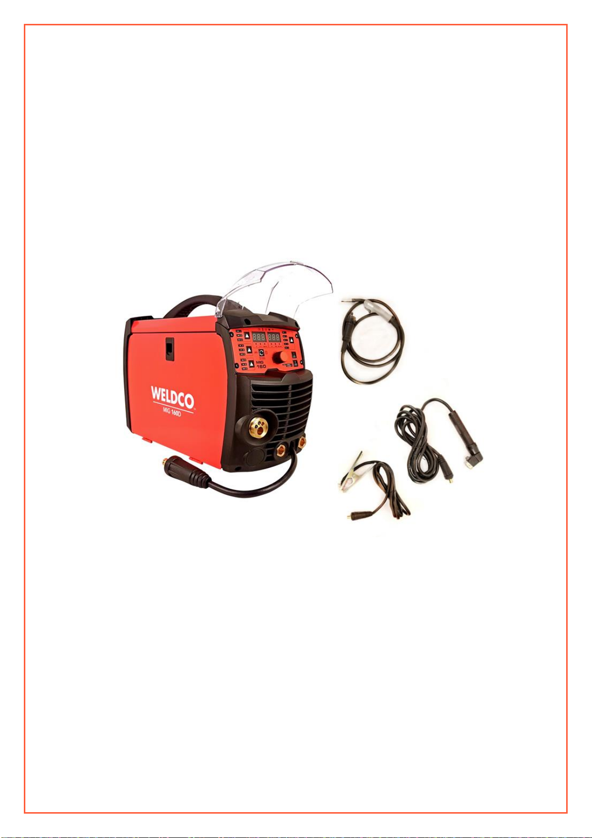
UNPACKING YOUR WELDER
Contents:
•MIG inverter power source.
•3m MB15 MIG torch
•Heavy duty earth clamp and lead.
•Heavy duty twist lock electrode holder and lead.
•0.8/0.9mm knurled roller = gasless (not shown)
•0.6/0.8mm V grooved roller = gas (not shown)
•0.9/1.0mm V grooved roller = gas (not shown)
•Gas tube (not shown)
•MIG accessory kit (not shown)
Please check all contents are correct and damage free before first use, if any issues please contact your local
dealer.

4
WELDING HAZARDS AND SAFETY
Welding poses a variety of hazards to health and safety. Please ensure you have correct safety equipment for yourself and those
within the welding area. Your local distributor will be able to assist you with the correct Weldco protective helmet and gloves.
Detailed documents can be located on the Worksafe website, www.worksafe.govt.nz, topic welding.
WORK AREA
•Ensure your work area is clear, dry and free of trip hazards.
•That the area is well ventilated, and all flammable materials are removed to a safe distance.
•Never leave your welder powered up – unattended.
FIRE RISK
•Due to the welding process producing molten metal including sparks and fumes maximum fire safety must always
be obeyed. Ensure you have direct access to the correct fire extinguisher for your environment.
•Never weld tanks or containers that have or have held flammable liquid, gas or where the contents are under
pressure. This should only be carried out by trained specialists.
•Ensure that the area is checked for smoldering materials as material will remain hot well after welding.
ELECTRICITY CAN KILL
•Never weld or attempt to weld in a wet or raining environments. There is a serious risk of electrocution to the
operator or those within the area.
•it is recommended that the welder be connected to an RCD.
FUMES AND GASES
•Welding produces fumes and gases that can be harmful to the operator and those within the surrounding areas.
Always ensure that there is plenty of ventilation and fresh air.
•Do not weld material that has been coated or contaminated with paint, varnish or rubber as they may give off
harmful fumes or gas and increase the risk of fire and or explosion.
PERSONAL PROTECTIVE EQUIPMENT AND CLOTHING
The user must comply with occupational health and safety rules and wear appropriate protective equipment.
BURNS
•The welding process causes the work piece and surrounding items to become hot.
•It is always recommended that flame resistant clothing be warn.
•Welding gloves must be worn to help prevent burns to hands and arms when handling hot objects.
•Avoid skin exposure to the Ultraviolet rays produced by the arc. It is recommended that skin be protected from
these harmful rays. Serious burns are possible when this recommendation is not followed.
•Approved welding helmets must be worn by the operator and any personnel with in 10m of the work area. It is also
recommended that welding safety screens are installed to protect.
•It is always recommended that enclosed footwear with rubber soles be worn to protect from sparks and molten
metal and to reduce the risk of electrocution.
•As welding produces gases and fumes many of these can be harmful it is recommended that the operator and
these in the direct area wear respirators with the relevant protection.
•Always where safety glasses when chipping the slag, scraping or preparing the work piece.

5
ELECTROMAGNETIC AND RADIO FREQUENCIES – “PACEMAKERS”
•Avoid contact with the energized work piece.
•Always ensure you have adequate protection from electrocution and burns.
•Since the welder owns strong electromagnetic and radio frequencies. Persons fitted with “PACEMAKERS” or similar
devices MUST consult their doctor before turning on the welder. This relates to both the operator and those
nearby.
PRE-CHECKS
The following items must be checked by the operator each time before powering up the power source.
•Ensure that the welder is damage free and no exposed wires.
•Check all welding cables, insulation and accessories are free of damage.
•The work area is checked and free of hazards
•All personal protective clothing and equipment is defect free.
•Access to Fire extinguisher and welding blanket.
•All flammable material has been removed.
WARNING!
•Disconnect the power source before servicing and ensure the device has powered down.
•Contact your dealer or reseller immediately should your welder require servicing.
•It is not recommended that you remove the covers to carry out your own servicing – doing so will void the
warranty.
STORAGE, TRANSPORTATION AND MAINTENANCE
•Your welder contains sensitive electronics and needs to be stored in a dust and moisture free environment.
•Periodically your welder should be blown down using dry compressed air to remove any dust and metal fillings.
•Once your power source and welder have cooled down. Remove your accessories for storage – wipe both the welder
and accessories down with a clean cloth to remove any contaminates.
•Store your welder in a dry safe environment.
•When transporting ensure that the power source, accessories and wire are secure.
•Cylinders need to be stored and transported as per NZ regulations and safe operating procedures.
6
TECHNICAL DESCRIPTION
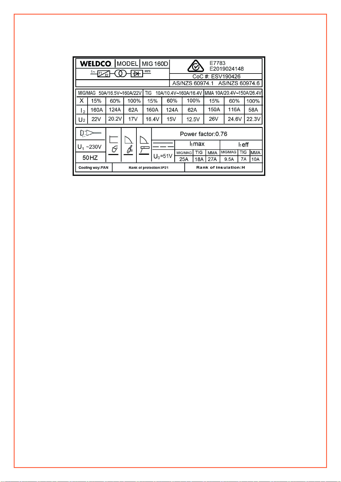
COMPLIANCE PLATE
Duty Cycle
The welder’s duty cycle is the number of minutes in a 10-minute period the power source can safety produce the set
welding current (actual arc on). If this is exceeded the machine will enter thermal overload, turning the welding current off
protecting the welder. This is indicated by the light on the front panel.
For example:
•At 124 amps the welder will MIG continuously for 6 mins and needs to rest for 4 mins.
•At 62 amps the welder will MIG continuously or 100% of the time.
The duty cycle is tested at 40 degrees celsius, if the welder is operating in lower temperature e.g. 20 degrees celsius the
duty cycle will be higher.
INPUT PLUG
The MIG160D is fitted with a 10amp plug. This machine is designed to work with 10amp domestic wall sockets. It is important
that the machine is plugged directly into the mains plug. If an extension cord must be used a minimum 2.5mm wire thickness is
require and no more than 10m in length.
Using unsuitable extension cords will reduce the input voltage (known as voltage drop) and this will void the warranty of your
machine.
OPERATING ENVIRONMENT
•Operating temperature: -10℃~40℃.
•Transportation and storage: -25℃~55℃.
•Relative air humidity: 40℃ ≤ 50%; 20℃ ≤ 90%.
•The dust, acids, corrosive gases and substance in the ambient air must be not higher than normal level.
•Altitude must be less than 1km.
•Good ventilation around the machine, at a distance of at least 50cm around.
•Power source must be kept on a level surface to reduce the risk of the machine falling.
7
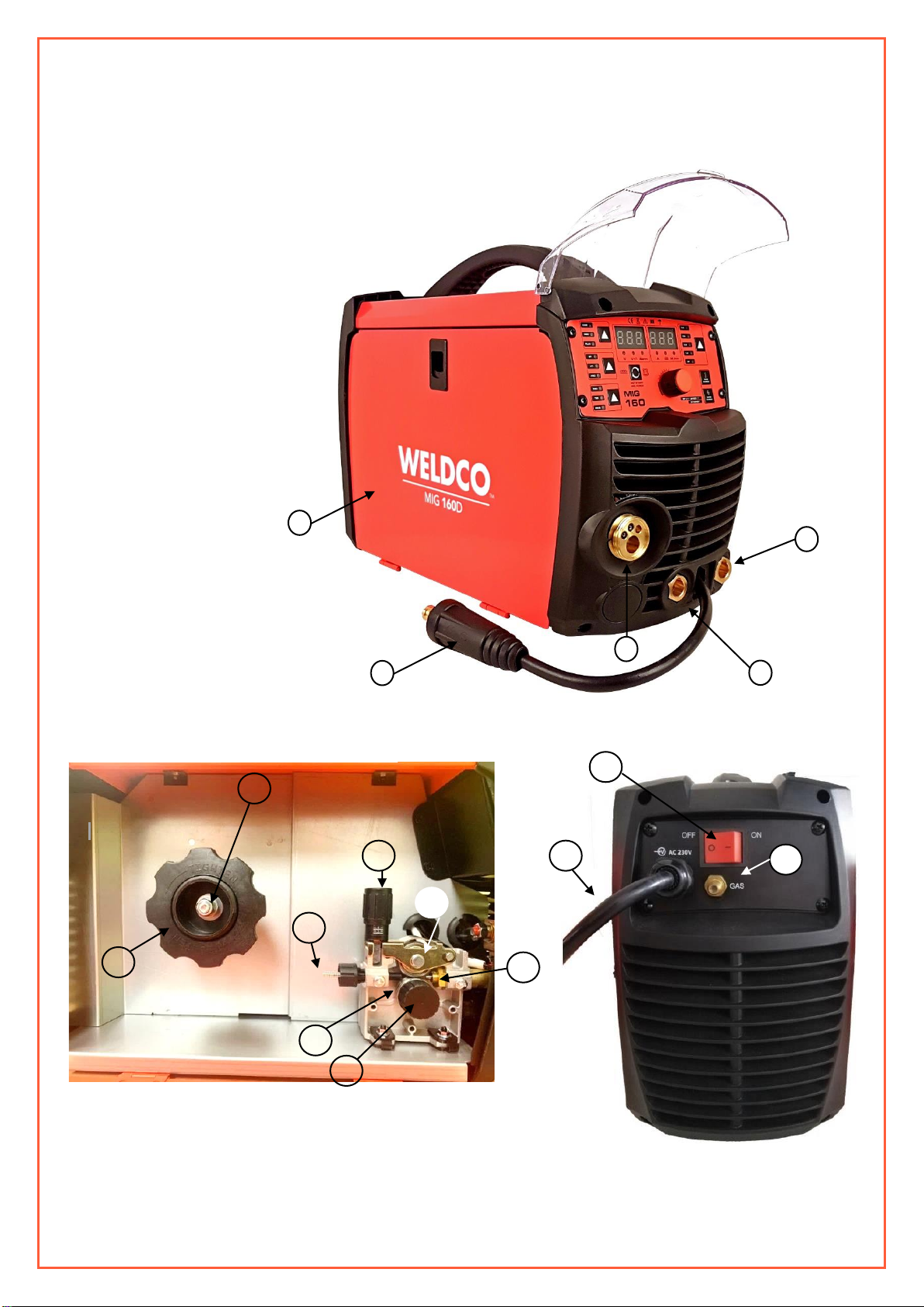
MACHINE LAYOUT
1. Female Euro Connector
2. Wire Feed Compartment door.
3. Negative Terminal
4. Positive Terminal
5. Polarity Cable
INSIDE – WIRE FEED COMPARTMENT
22. Spool Retainer Nut
23. Spool Brake Tensioner
24. Tensioner Adjuster
25. Tensioner Arm
26. Outer guide Tube
27. Roller Retainer Bolt
28. Drive Roller
29. Inner guide Tube
REAR PANEL
30. ON OFF Switch
31. 10amp 230-volt Power Cable and Plug
32. Gas Inlet
4.
3.
5.
1.
23.
22.
24.
29.
25.
26.
28.
27.
2.
REAR PANEL
INSIDE WIRE FEED COMPARTMENT
31.
32.
30.
8
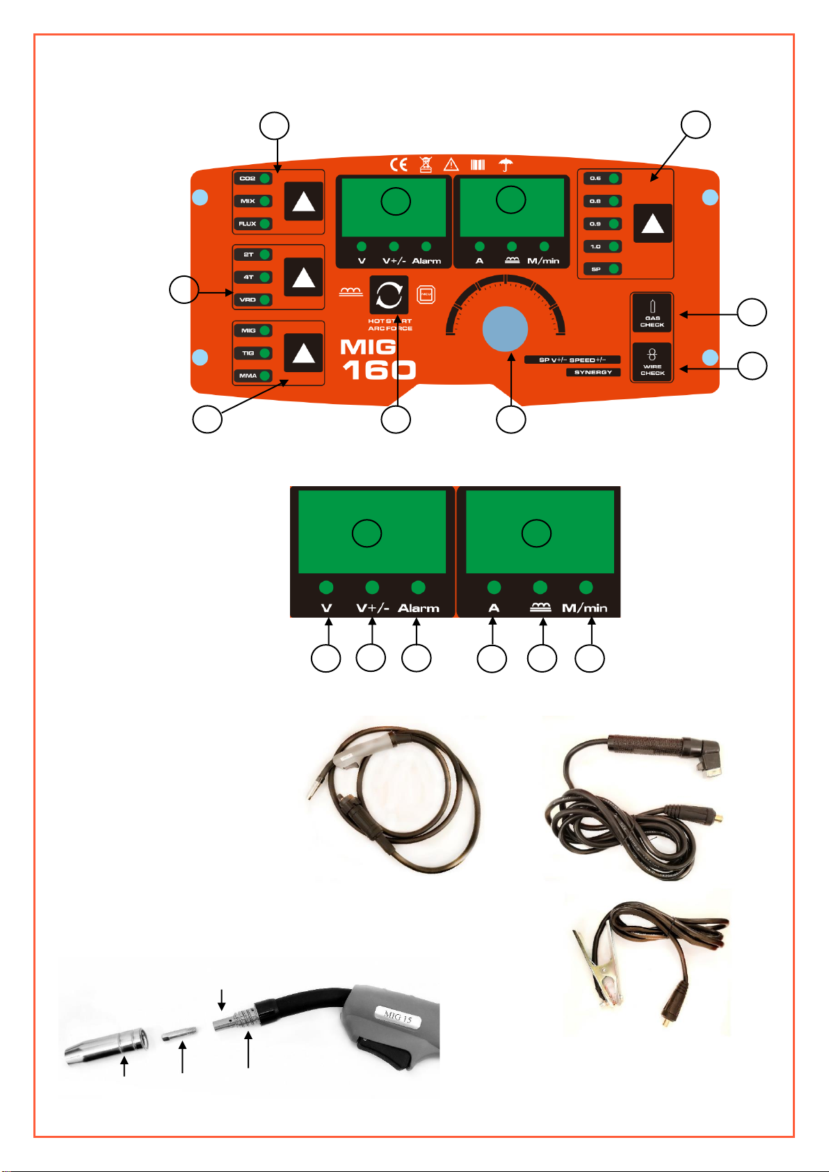
CONTROL PANEL LAYOUT
MIG Torch
MIG TORCH EXPLODED
Electrode Holder
Earth Clamp
Gas Nozzle
Tip Adapter Spring
Welding Tip
Tip Adapter
6. Voltage Display
7. Amperage Display
8. Wire Selector
9. Gas Test
10. Wire Feed
11. Main Adjustment
12. Step Selector
13. Welding Process
Selector
14. Torch Control & VRD
15. Gas selector
16. Voltage
17. Voltage Adjust
18. Alarm
19. Amperage
20. Inductance
21. Wire Feed
15.
16.
17.
18.
6.
7.
14.
11.
12.
13.
9.
10.
8.
7.
6.
21.
20.
19.
9
SETUP FOR MIG WELDING
Smooth consistent wire feed is critical to achieve professional results.
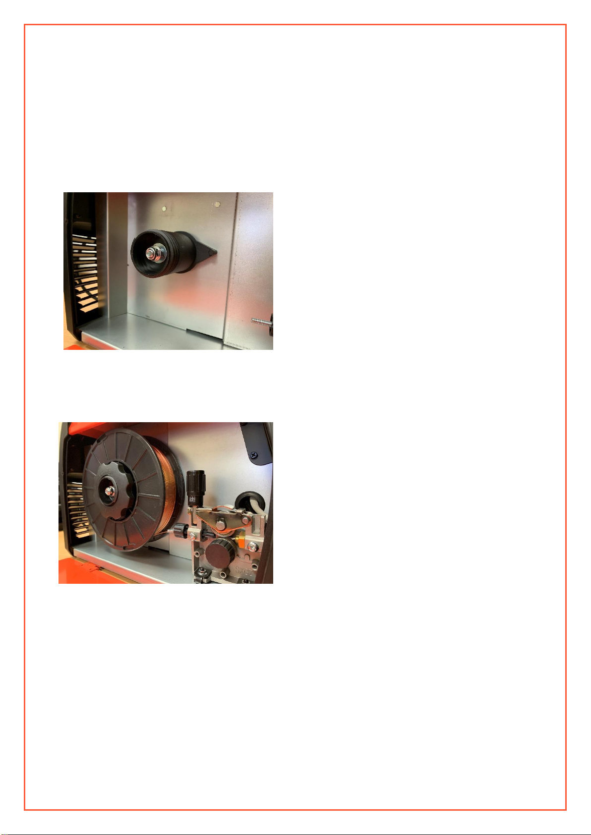
FITTING THE WIRE 5KG/200MM DIAMETER WIRE SPOOL
1. Open the cover door (2) for the wire feed compartment. Remove the wire spool retaining nut (22) by threading the
retainer clockwise.
2. Fit the 5Kg/200mm diameter wire spool to the spool holder, lining up the locating pin with the locating plug on the
spool. Ensure the end of the wire feeds towards the drive rollers from the bottom of the spool.
3. Refit the wire spool retaining nut (22) and tighten anti clockwise hand tight.
4. Set the spool brake tensioner by rotating the adjustment nut (23).
To increase brake tension, turn clockwise. Turn anti-clockwise to decrease brake tension.
Set the spool brake tension so that the spool can rotate freely, without continuing to rotate once the wire feed stops.
Check performance from time to time to ensure that the wire is feeding correctly, especially as the wire spool empties.
Always reset when replacing with a new spool.
10
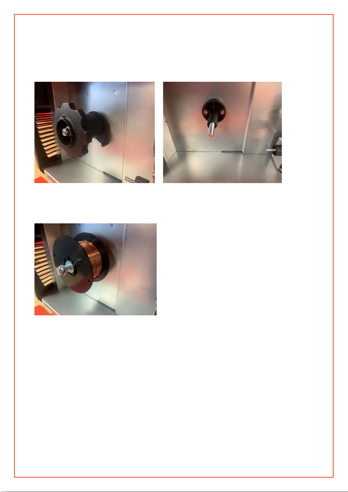
FITTING THE WIRE 1KG/100MM DIAMETER WIRE SPOOL
1. Open the cover door (2) for the wire feed compartment. Remove the tensioning nut, washer’s and spring.
Slide off spool holder –keep in a safe place.
2. Fit the 1Kg/100mm diameter wire spool on the shaft. Ensure the end of the wire feeds towards the drive rollers
from the bottom of the spool.
3. Refit the washer’s, spring and tensioning nut. Set the spool brake tensioner by rotating the adjustment nut (23).
Ensure there is tension on the spool before fitting the wire into the wire feeder (spool will un-ravel).
To increase brake tension, turn clockwise. Turn anti-clockwise to decrease brake tension.
Set the spool brake tension so that the spool can rotate freely, without continuing to rotate once the wire feed stops.
Check performance from time to time to ensure that the wire is feeding correctly, especially as the wire spool empties.
Always reset when replacing with a new spool.
Table of contents
Other WELDCO Welding System manuals


Popular Welding System manuals by other brands


TAFA
TAFA 30*8B35 owner's manual

Lincoln Electric
Lincoln Electric INVERTEC V350-PRO CE Technical specifications

ESAB
ESAB Buddy Arc 145 instruction manual

CIGWELD
CIGWELD 636804 use instructions

Red-D-Arc
Red-D-Arc DC-400 Operator's manual

Hobart Welding Products
Hobart Welding Products Spool Gun DP 3035-10 owner's manual


