Weldex WDN-2308X Series User manual

OPERATION MANUAL
Built-in x 23 ZOOM
AUTO FOCUS COLOR CAMERA
WDN-2308X Series
WDAC-2308X Series
READ AND KEEP THIS OPERATION MANUAL

Warning:
This equipment generates and uses radio frequency energy
and if not installed and used properly, I.e., in strict accordance
with the instruction manual, may cause harmful interference
to radio communications. It has been tested and found to comply
with the limits for a Class Acomputing device pursuant to Subpart
J of Part 15 of FCC Rules, which are designed to provide reasonable
protection against such interference when operated in a commercial
environment.
Warning:
TO PREVENT FIRE OR SHOCK HAZARD, DO NOT EXPOSE THIS
APPLIANCE TO RAIN OR MOISTURE.
CAUTION
RISK OF ELECTRIC SHOCK
DO NOT OPEN
CAUTION:
TO REDUCE THE RISK OF ELECTRIC
SHOCK, DO NOT REMOVE COVER
(OR BACK). NO USER SERVICEABLE
PARTS INSIDE.
PREFER SERVICING TO QUALIFIED
SERVICE PERSONNEL.
Indicate a potentially hazardous situation which if not avoided,
may result in minor or moderate injury. It may also be used to
alert against unsafe practices.

CAUTION FOR SAFE OPERATION
1. Water and Moisture
To prevent fire or shock hazard, do not expose this camera
to rain or moisture.
2. Servicing
Do not attempt to disassemble or repair by yourself.
You may be exposed to dangerous voltage or other hazards.
Note that all servicing is qualified service personnel.
Modifications not approved by manufacturer could
void the user's authority to operate the equipment.
3. Power Sources
To prevent electric shocks and risk of hazards, do NOT use
more than the specified power source.
4. Environment
Do not install too warm or too cold place. Recommended
operation temperature is between -5℃and 60℃
5. Sunlight
Do not point the camera at the sun. CCD can be damaged.
6. Heavy Shock and Vibration
Do not drop the camera or subject it to heavy shock of
vibration.
7. Install on an Unstable Place
Do not place or install this camera on an unstable place,
stand, tripod, bracket or table. That may cause serious injury
to people or damage to appliance.
8. When operation is incorrect or a malfunction is observed
While operating, if any abnormal condition (strange sound,
smell or smoke) or a malfunction (no pictures, etc.) is
observed, stop using the camera immediately, turn the
power off, then contact your supplier.
9. Cleaning
Turn the power off and wipe off the dirt with a dry soft
cloth. If it is extremely dirty, use furniture cleaner to wipe it
off. To clean the lens, use a blower or lens cleaning
tissue. (available from any camera dealer)
10. Do not shoot any source of bright light.
If the objects contain very bright areas, bright vertical or
horizontal lines may appear on the screen. This is called
"smear" , a Phenomenon which often occurs with solid
- state pickups, and is not a malfunction.
11. Damage Requiring service
Unplug the camera from the power source and refer
servicing to qualified service personnel under the following
condition:
a. If the power-supply cord or plug is damaged.
b. If the camera has been exposed to rain or water.
c. If liquid has been spilled, or objects have fallen into the camera.
d. If the camera does not operate normally by following the operating
instructions. Adjust only those controls that are covered by the
operating instructions as an improper adjustment of other controls
may result in damage and will often require extensive work by a
qualified technician to restore the camera to its normal operation.
e. If the camera has been dropped or the cabinet has been damaged.
f . If the camera exhibits a distinct change in performance.
- 2 -

CONTENTS
1. Features -------------------------------------------------------------- 4
2. Names & Functions ---------------------------------------------- 5
5. On Screen Display -------------------------------------------------- 9
Thank you for using this Auto Focus Zoom Color Camera. To get the best
efficiency, read carefully all instructions in this manual before use, and
keep this manual for reference. If you have any problems with this camera,
contact your supplier to service.
4. Camera Control Methods------------------------------------------ 7
6. Communication Protocol------------------------------------------ 14
8. Dimensions ---------------------------------------------------------- 28
7. Specifications-------------------------------------------------------- 26
3. Installation----------------------------------------------------------- 6
- 3 -

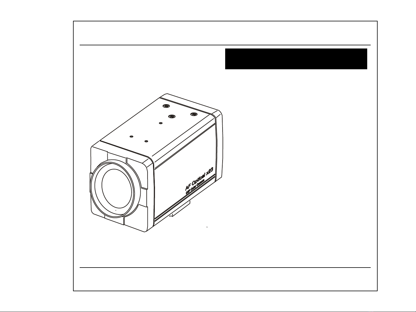
Ideal Digital Video Camera for Security
2308X Series is a compact camera that offers easy system
integration.Coming with the built-in zoom lens,the user can monitor
the scene from variable angle without the extra lens.
And,with the D.S.P. technology,such intelligent controls as auto iris ,
auto back light compensation and auto white balance are possible to
realize clear detailed picture. Additionally,through RS-232C/RS-485
linkage, remote Focus/Zoom operations are also possible,along with
manual control.All these features including highly sensitive 1/4-inch
CCD make the ideal digital processing CCTV camera 2308X Series
more effective surveillance activities.
Built -in Optical power zoom lens
2308X Series with highly durable built-in zoom lens offers auto focus,
auto iris , and optical zoom functions enabling the user to monitor
a scene with clarity in any desired angle of view. With the x23 optical
zoom lens and up to x8 digital zoom processing,zoom ratio of the
2308X is expanded to x184.
High Resolution & sensitivity SONY CCD
The chassis features a highly sensitive 1/4-inch CCD pickup with
approximately 380,000(NTSC), 440,000(PAL) effective pixels
minimizing residual image and geometric distortion. All images are
reproduced with a high horizontal resolution of 470(NTSC),
450(PAL) TV lines for fine detail.
Remote Control through RS232C/RS485 Interface
Remote control operations are possible through RS232C/RS485
interface for Focus and Zoom (optical:up to x23,digital ~ x8) control.
In addition,the unit lets you command white balance and exposure
manually using RS232C/RS485 interface.
Compact size for various applications
2308X Series comes in the compact aluminum case enabling
the users put the unit into the other forms of other outer case
( such as large dome camera or built in P/T/Z applications)
according to the particular purpose.
1. Features
AI / Fuzzy Control Circuit with DSP
Advanced DSP(Digital Signal Processor) technology automatically
adjusts operations such as Iris , White Balance flexibly adapting to
environmental conditions.
Auto Iris :the iris is adjusted so that visual output is kept at a fixed
level,even if brightness of the surrounding changes.
Auto White Balance :color adjustment according to the color
temperature of the light source illuminating the subject.
white balance can be obtained even with fluorescent
lights, halogen lamps or outdoor.
Manual Function Control( Key or Using RS-232C )
Following functions can be controlled manually
1) NEGA/POSI ;Negative/Positive
2) Digital Zoom ; x2 ~ x8 (Addition to Optical Zoom)
3) Iris Control ; Auto/Manual (Manual Iris level UP/DOWN)
4) AGC ; 8 dB ~ 38 dB Adjustable
5) White Balance ; Auto/Manual/Indoor/Outdoor/ATW
6) Manual White Balance ; R,B UP/DOWN
7) 64 Positions Zoom/Focus Preset
8) Power ON/OFF
9) Quick Zoom Control ; TELE/WIDE
10) Focus ; Auto/Manual/One shot ( PushAuto )
11) Manual Focus ; NEAR/FAR
12) On Screen Display Menu ; ALL Display / only Top / only Bottom
Display off
13) 28 Steps Shutter Speed Control
14) Back Light Compensation ; ON/OFF/AUTO
15) Back Light level ; 00 ~ 80
16) Color ; ON/OFF
17) Mirror ; ON/OFF
18) Zoom Speed ; High/Medium/Low
19) Oneshot AF time ; 1 sec ~ 9 sec
20) AF sensitivity ; High/Low
21) Communication Baud-rate ; 1,200bps ~ 115,200bps
22) AE sensitivity ; High/Low
23) Minimum shooting distance ; 1cm ~ Infinity ( ∞ )
24) simple privacy area masking ; 6 areas
- 4 -

2. Names & Functions
TELE(UP) BUTTON
NEAR(+) BUTTON
FAR(-) BUTTON
MENU DISPLAY BUTTON
WIDE(DOWN) BUTTON
POWER INPUT TERMINAL
CAMERA CONTROL CONNECTOR
VIDEO OUTPUT
S-VIDEO OUTPUT
POWER ON LAMP
This is the output terminal
for composite video signal .
This is the output terminal
for separate Y/C signal .
In power ON state , this LED is ON . This is the 14 pin connector for external
camera controls .
( Refer to 4. CAMERA CONTROL METHODS )
DC 12V input
( Please use a specified DC adaptor)
( Be careful its polarity )
CONT
VIDEO
POWER
SVIDEO
- 5 -

3. Installation
3.1 Check all accessories with enclosed package .
- 2308X Series SET
- 14 PIN CONNECTION CABLE
- OPERATION MANUAL ( ENGLISH EDITION)
2308X Camera 14 PIN CONNECTION CABLE OPERATION MANUAL
14P CABLE DESCRIPTION ;
1. KEY1 ( RED ) 2. KEY2 ( YELLOW )
3. ZOOM ( GREEN ) 4. FOCUS ( BLUE )
5. MENU ( WHITE ) 6. COM ( ORANGE )
7. GND ( BLACK ) 8. GND ( BLACK )
9. R+/NC ( BROWN ) 10. R-/RD ( PINK )
11. T+/TD ( VIOLET ) 12. T-/GND ( GRAY )
13 EXT_VD ( WHITE ) 14. GND ( BLACK)
- 6 -

4.1 Remote Control using for Hard wired connection ( Connector pin 3,4,5,6 )
4. Camera Control Methods
4.2 Remote Control using for RS-232C connection ( Connector pin 10,11,12 )
Connect to Serial PORT
( COM1 or COM2 )
14P Cable
14P Cable
10
11
12
RD ( TxD )
TD ( RxD )
GND
14P Cable
Serial Cable
Serial Cable
( 9 Pin D-Sub )
2
RD
3
TD
5
SG
4
6
7
8
Connect internally
for communication
3
4
5
ZOOM
FOCUS
MENU
14P CableController
6COM
Relay
Relay
Relay
TELE (-)
WIDE(+)
NEAR(+)
FAR (-)
MENU ON
- 7 -

4.3 Remote Control using for RS-422/485 connection ( Connector pin 9,10,11,12 ) -------- OPTION
Connect to Serial PORT
(COM1 or COM2)
14P Cable
Serial Cable
10
11
12
RD ( TxD )
TD ( RxD )
GND
14P Cable
Serial Cable
( 9 Pin D-Sub )
2
RD
3
TD
5
SG
4
6
7
8
Connect internally
for communication
485 Converter
9
10
11
R +
R-
T+
14P Cable
485 Converter
T+
T-
R+
12 T-
R-
422
9
10
11
R +
R-
T+
14P Cable
485 Converter
TRxD+
TRxD-
12 T-
485
- 8 -

5. On Screen Display
<Fig5-1. Operating OSD display position>
① ② ③,④ ⑤
⑥
⑦ ⑦
⑦
⑤WB MODE
ATW Auto Trace White Balance
Indoor Preset (3200°K)
Outdoor Preset (5400°K)
Manual WB mode
AWC One Push mode
ZOOM
DISPLAY
CAMERA
ID
①
OSD Format DESCRIPTION
②
FUNCTION
Focus Mode Non display
MF
Auto Mode
Manual / Push_Auto Mode
Back Light Back Light OFF
Back Light ON
④Shutter Speed
Normal Shutter
( NTSC:1/60 PAL :1/50 )
1 / 125
.
.
.
.
1 / 1 0, 0 0 0
28 variable steps.
Non display
Non display
BL
IN
OUT
MWB
③Flickerless Flickerless OFF
Flickerless ON
Non display
FL
x23
⑥
⑦
Dx50
>> TELE
<< WIDE
Optical zoom
Digital zoom
zoom TELE
zoom WIDE
Non display In case that ID is 0
ID : 002 In case that ID is 1 ~ 255
5.1 How to display Operating OSD
a. Pressing the MENU key softly confirm current Operating OSD.
It is disappeared about five seconds later if there are no other key actions.
b. When it zoom in or out pressing TELE(up) or WIDE(down) key,
whole Operating OSD is displayed and then disappeared.
Press NEAR(+) , FAR(-) key, only upper part of Operating OSD
( for displaying camera mode ) is displayed and then disappeared.
(It is for checking current whole camera mode and zoom position )
c. Even though Operating OSD is disappeared,
it keep displaying ID in lower part of screen.
In order to do not display ID, one method is to change EEPROM data
of Camera, the other is to use external communication through RS-232C.
d. Using RS-232C communication, change display position of ID;
Bottom Right -> Top Left -> Top Right -> Non display.
* If display Operating OSD is not needed by special purpose
like using external text overlay board, it can be OFF mode at all times
through external communication control as RS 232C.
<Table5-1. Operating OSD description>
- 9 -

5.2 Display SETUP MENU
a. Press MENU key above 2 seconds so that SETUP MENU 1 is displayed
on the screen.
b. Select item of SETUP MENU using TELE(up) / WIDE(down) key.
c. NEAR(+) / FAR(-) key is used to increase / decrease data of selected item.
5.3 Move between SETUP MENU 1 and SETUP MENU 2
a. In order to change from SETUP MENU1 to SETUP MENU 2,
select NEXT MENU using TELE / WIDE key, and press NEAR / FAR key.
b. In order to change from SETUP MENU 2 to SETUP MENU1 ,
select PREV. MENU using TELE / WIDE key, and press NEAR / FAR key.
5.4 Quit SETUP MENU
a. Press the MENU key again. SETUP MENU is disappeared,
“SAVE?” or “QUIT?” is displayed at center of screen.
If there is no change of adjustment state of Camera,
“QUIT?” is showed, else “ SAVE?” is showed.
①“QUIT?” : quit SETUP MENU without saving changed value.
②“SAVE?” : quit SETUP MENU with saving changed value.
b. Press NEAR / FAR key to choose, and press the MENU key again.
whole SETUP MENU is quitted.
( If MENU key is not pressed and TELE / WIDE key is pressed,
SETUP MENU is appeared again. )
5.5 SETUP MENU 1 functions
①Backlight Compensation
: It is for preventing the center object too darken when the excessive light is
behind the center object. Press NEAR/ FAR key so that Backlight mode switch
ON/OFF. Set BACKLIGHT ON, then brighten the center object in the contrast to
the background light. Press NEAR/ FAR key in 2 sec, Backlight mode become
AUTO. When mode is AUTO, camera discriminate backlight condition and
compensate automatically. It can be changed backlight detection region of screen .
According to changing backlight region its control is more smoothly and becomes
proper brightness status.
BACKLIGHT OFF → ON → (AUTO) → . . . .
②COLOR / Black&White Mode
: Use for changing color and monochrome ( black & white )mode .
ON is Color mode, OFF is black&white mode.
COLOR ON → OFF → . . . .
③Positive / Negative Mode
: Use for Positive and Negative mode. ON is Negative mode, OFF is Positive
mode namely general screen state.
NEGATIVE OFF → ON → . . . .
<<SETUP MENU 1>>
①BACKLIGHT
②COLOR
③NEGATIVE
④MIRROR
⑤SHARPNESS
⑥BRIGHTNESS
⑦FLICKERLESS
⑧MAX AGC
⑨INITIAL SET
NEXT MENU
>>SETUP MENU 1<<
.
.
.
.
.
.
NEXT MENU
>>SETUP MENU 2<<
.
.
.
.
.
.
PREV. MENU
<Fig5-2. SETUP MENU change>
<Fig5-3. SETUP MENU 1 >
OFF
ON
OFF
OFF
10
48
OFF
34dB
ON
- 10 -

ⅰ)Set AUTO BLC mode
>> SETMENU 1 <<
BACKLIGHT AUTO
.
.
.
.
.
NEXT MENU
Press NEAR(+) or FAR(-)
key above 2 sec, then Backlight
mode becomes Auto.
Press MENU key , then
displayed backlight area
that can be modifying
( Refer to B )
1
5
Press MENU key , then
displayed SETUP MENU1
again. At this time bellow
item ( color ON/Off )becomes
blinking status.
>> SETMENU 1 <<
BACKLIGHT AUTO
COLOR ON
.
.
.
.
NEXT MENU
ⅱ)Set BLC area in Backlight Auto mode
If you want to change BLC
area , Move to desirable area
using TELE(up)/WIDE(down)
key .
1
5
The selected area becomes
blinking.
1
5?
Press NEAR(+)or FAR(-) key ,
New area is selected, next
area is blinking. It can be selected
or removed all 5 areas with above
setting method repeatedly.
1
53 ?
If you want to remove current
selected area ,
Press NEAR(+)or FAR(-) key ,
current area is removed.
1
5
Press MENU key , then
PREV. to previous SETUP
MENU 1.
>> SETMENU 1 <<
BACKLIGHT AUTO
COLOR ON
.
.
.
.
NEXT MENU
< Fig 5-4. Five BLC areas >
1
5 43
2
- 11 -

④Mirror Mode
: Mode ON is Mirror mode, Mode OFF is general screen state.
MIRROR OFF → ON → . . . .
⑤Sharpness Control
: Use to change the contour of scene .
SHARPNESS 0 ~ 15
⑥Brightness Control
: Adjust open and close level of iris in AI mode. The normal value is 48(50).
The smaller brightness value is, the darker it is, because iris is
closed more. On the contrary the bigger brightness value is,
the brighter it is, because iris is opened more.
BRIGHTNESS 0 ~ 99
⑦Flickerless Mode
: Set FLICKERLESS ON to remove the flicker of picture.
Shutter speed is fixed as 1/100(NTSC) sec, 1/120(PAL) sec .
FLICKERLESS OFF → ON → . . . .
⑧Max AGC control
: Set AGC level.
MAX AGC OFF → 8dB → 10dB → . . . . → 36dB → 38dB
⑨INITIAL SET Mode
: Set the INITIAL SET Mode ON so that all changed data are returned to
shipping condition. Mode becomes OFF if SETUP MENU state is different
from shipping condition.
INITIAL SET OFF → ON → . . . .
5.6 SETUP MENU 2 functions
ⓐWhite Balance Mode
: Outer illumination condition is expressed by Color temperature ,Kelvin
(°K). It is White Balance that shows white as white in any illumination
conditions. It is composed of five modes.
ATW ( Auto Trace White balance )
: do automatically under any condition in range 2,800°K ~ 8,000°K
It can be adjustable red and blue point of desired white position
INDOOR ( Indoor Preset WB )
: Use to set the preset illumination condition as 3200°K.
OUTDOOR ( Outdoor Preset WB )
: Use to set the preset illumination condition as 5400°K.
MANUAL ( Manual WB )
: Use to adjust to desired color temperature manually.
(0 ~ 99 decimal value )
AWC ( Auto White Control )
: Consider current illumination condition, do white balance by force
and lock as manual.
ⓑWhite Balance Mode Control
: It displays and changes White Balance Mode Control status of Camera.
ATW AUTO ( It doesn’t need to adjust. )
INDOOR 3200°K ( It doesn’t need to adjust. )
OUTDOOR 5400°K ( It doesn’t need to adjust. )
MANUAL 50 ( It can be adjust )
AWC LOCK → PUSH → . . . .
(LOCK means Manual white balance status. Press NEAR(+) / FAR(-)
key continuously, LOCK mode becomes PUSH mode and white balance
acts automatically, and then white balance mode is locked as manual.)
ⓒSet Focus Mode
: It is composed of three modes.
AUTO : Use to focus automatically all the time.
MANUAL : Use to focus manually by pushing NEAR(+) / FAR(-)key.
Even though MANUAL mode, it will be focused in about 5 seconds after
zoom in(TELE) / out(WIDE), and return to MANUAL mode automatically.
This is for focusing accurately after zooming.
ONESHOT(option) : It is similar to MANUAL mode.
But there are some difference.
In case the focus mode is ONESHOT, it is focused whenever ONESHOT
(AUTO/MANUAL key) key is pushed. It will be returned to MANUAL mode
after the fixed seconds even though can not be found best focus.
(Taking time is able to set in Special Menu. ) In this case
push ONESHOT(AUTO/MANUAL key) key again, it will be in best focus.
PUSHAUTO(option) : While pushauto key is pushing, focus mode is auto.
☞
caution
1. According to Model, focus mode is Auto -> Manual -> Oneshot
or Auto -> Manual -> Pushauto.
< Fig 5-5. SETUP MENU 2 >
<<SETUP MENU 2>>
ⓐWB MODE
ⓑWB CONT
ⓒFOCUS SET
ⓓSTART ZOOM
ⓔEND ZOOM
ⓕID DISPLAY
ⓖSPECIAL MENU
PREV. MENU
ATW
AUTO
ONESHOT
x1
x184
OFF
- 12 -

ⓓSet Start Zoom ratio
: Set boundary value of WIDE zooming.
START ZOOM x 1 ~ x 22 ( in optical zoom region )
ⓔSet End Zoom ratio
: Set boundary value of TELE zooming. It can be set up to 184 x including
electronic zoom. ( in case the digital zoom limit is 8 times ) Since Start Zoom
and End Zoom ratio are set, simultaneously Camera moves to setting zoom
times. So it can be enable to adjust in moving to desired position.
END ZOOM x 23 ~ x 184 ( in digital zoom region )
☞
caution
1. End Zoom value must be lager than Start Zoom ratio.
ⓕCamera ID Display Mode
: Camera ID is indicating number assigned each Camera in case of
controlling many Cameras. It is from 0 to 255. But in case of 0, that is not
displayed on screen. It is always displayed even though whole Operating
OSD is disappeared on the screen. But it is possible to make non display
and to choose display position (BOTTOM RIGHT, TOP RIGHT, TOP LEFT)
by RS-232C communication.
ID DISPLAY 0 ~ 255
☞
caution
1. In case of Camera ID FIX model, it cannot be selected.
ⓖSpecial Menu (Option)
: Use for Entering Special Menu.
<<SPECIAL MENU>>
ⓐAF SENS.
ⓑZOOM SPEED
ⓒO.S. AF TIME
ⓓMIN DIST
ⓔSHUTTER
ⓕBAUD RATE
ⓖAE SENS.
ⓗBLC LEVEL
ⓘOSD DISP.
RETURN MENU
HIGH
HIGH
5sec
50cm
NORMAL
9600bps
HIGH
24
ALL
ⓐAF SENS. Control
: High : Reaction of Auto Focus is fast. It can be used when it shoot
objects moving fast.
Low : Auto Focus is more stable. In fast moving scene, AF doesn’t work
even though the scene is changed. It is for stabilizing the scene.
AF SENS. HIGH → LOW → ….
ⓑZOOM Speed Control
: Set the zoom speed.
ZOOM SPEED HIGH → MEDIUM → LOW
ⓒOneShot AF TIME control
: Set the Oneshot taking time in Focus mode.
O.S. AF TIME 1sec ~ 9 sec
ⓓSet Minimum Distance
: Set the minimum distance which can be focalized.
MIN DIST 1cm → 10cm → 50cm → 1m → 3m → 10m → infinity
ⓔShutter Speed Control
: Set the Shutter Speed. (Refer to. 17page Table 6-1)
At this time, Exposure mode becomes Shutter Fix mode.
SHUTTER NORMAL→ 1/125 → … → 1/10000 → NORMAL
ⓕSet BAUD RATE
: Set Baudrate to communicate by RS232C, RS485, RS232TTL.
BAUD RATE 9600bps → 1200bps → 2400bps → 4800bps →
19200bps → 38400bps → 76800bps → 115kbps
ⓖAE SENS. Control
AE SENS. HIGH → LOW
ⓗSet BLC Level
BLC LEVEL 24 ( 0 ~ 80 variable )
ⓘSet Operating OSD display
OSD DISP ALL → NONE → TOP → BOTTOM → ALL → ...
ALL : Display all operating OSD ( Focus mode& key action status
, Zoom position , ID Display )
NONE : Clear all OSD except MENU page
TOP : Display top position OSD only ( Focus mode , key action
status)
BOTTOM : Display bottom position OSD only ( Zoom position , ID )
5.7 SPECIAL MENU functions
< Fig 5-6. SPECIAL MENU >
- 13 -

6. Communication Protocol ( RS-232C,RS-422)
①byte1 : command 1
(which kind of protocol is this to communicate between A and B.)
②byte2 : command 2
③byte3 : command 3
④byte4 : command 4
⑤byte5 : ID (To communicate cameras, each camera has its ID 0~255)
⑥byte6 : checksum ( byte1 + byte2 + byte3 + byte4 + byte5 = C/S )
Command 2 is real acting code, and command 3, 4 are decided
according to command 2. ( Refer to 6.2~6.16 )
6.1.3 Camera send 9bytes to PC.
①byte1 : command 1 received from PC
②byte2 : command 2 received from PC
③byte3 : command 3 received from PC
④byte4 : command 4 received from PC
⑤byte5 : send data 1
⑥byte6 : send data 2
⑦byte7 : send data 3
⑧byte8 : send data 4
⑨byte9 : checksum
( byte1 + byte2 + byte3 + byte4 + byte5 + byte6 + byte7 + byte8 = C/S )
-. byte1 ~ 4 must be same byte1 ~ 4 which PC send to Camera.
( If they are different , that means communication error. )
-. send data 1 ~ 4 are decided according to command 1~ 4.
6.1 Serial Communication
6.1.1 Communication Format
A) Data length : 1byte (8bit)
B) Start bit / Stop bit : 1bit
C) Parity bit : none
D) Baud rate : 9600bps
6.1.2 PC send 6bytes to Camera.
byte1 byte2 byte3 byte4 byte5 byte6
byte1 byte2 byte3 byte4 byte5 byte6 byte7 byte8 byte9
①0xC5 means this protocol is to communicate between PC and CAMERA.
②To communicate camera, read Camera ID first.
③byte5 is Camera ID.
④dum is dummy data that can be ignored.
⑤C/S = 0xC5 + 0xCC + 0x00 + 0x00+ 0x00 = 0x91
6.2.2 Change Camera ID
6.2 Camera ID
6.2.1 Read Camera ID
0xC5 0xCC dum dum dum C/S
0xC5 0xCC dum dum byte5 dum dum dum C/S
①byte3 is New Camera ID which is to change .
②ID is current Camera ID.
6.2.3 Camera ID display ON/OFF
0xC5 0x78 byte3 dum dum dum dum dum C/S
0xC5 0x78 byte3 dum ID C/S
0xC5 0xAA 0x6A dum ID C/S
0xC5 0xAA 0x6A dum dum dum dum dum C/S
①Switch Camera ID display ON/OFF
②If the Camera ID is 0x00, then it’s not displayed.
6.2.4 Camera ID display position
0xC5 0x80 dum dum ID C/S
0xC5 0x80 dum dum dum dum dum dum C/S
①Change camera ID display position.
②Bottom Right -> Top Left -> Top Right -> No display -> Bottom Right -> …
③Whenever this command is sent, position of ID is changed in upper order.
- 14 -

6.3 EEPROM
6.3.1 Read EEPROM data (front 2K byte out of 4K byte)
0xC5 0xF0 byte3 dum ID C/S
0xC5 0xF0 byte3 dum byte5 dum dum dum C/S
①byte3 is EEPROM address to read ( 0x00 ~ 0xFF )
②ID : Camera’s ID ( Refer 6.2.1)
③byte5 is EEPROM data of EEPROM address
6.3.2 Write EEPROM data ( front 2K byte out of 4K byte )
①byte3 is EEPROM address to write ( 0x00 ~ 0xFF )
②byte4 is data to write on EEPROM address
6.4 White Balance Mode
6.4.1 Read WB mode
0xC5 0x0F byte3 byte4 ID C/S
0xC5 0x0F byte3 byte4 dum dum dum dum C/S
①byte5 = 0x00 ; ATW mode
②byte5 = 0x02 ; INDOOR WB mode
③byte5 = 0x03 ; OUTDOOR WB mode
④byte5 = 0x04 ; MANUAL WB mode
⑤byte5 = 0x05 ; AWC mode
6.4.2 Set WB mode
0xC5 0xAA 0x83 dum ID C/S
0xC5 0xAA 0x83 dum byte5 dum dum dum C/S
①byte4 = 0x00 ; ATW mode
②byte4 = 0x02 ; INDOOR WB mode
③byte4 = 0x03 ; OUTDOOR WB mode
④byte4 = 0x04 ; MANUAL WB mode
⑤byte4 = 0x05 ; AWC mode
0xC5 0xAA 0x65 byte4 ID C/S
0xC5 0xAA 0x65 byte4 dum dum dum dum C/S
①byte4 = 0x00 ; AWC mode “Lock”
②byte4 = 0x01 ; AWC mode “Push”
6.4.4 Read HUE data at the MANUAL WB mode
6.4.3 Set AWC mode
0xC5 0xAA 0x78 byte4 ID C/S
0xC5 0xAA 0x78 byte4 dum dum dum dum C/S
①byte5 is the current HUE data at MANUAL WB mode (0x00 ~ 0x63).
6.4.5 Adjust HUE data at the MANUAL WB mode
0xC5 0xAA 0x87 dum ID C/S
0xC5 0xAA 0x87 dum byte5 dum dum dum C/S
0xC5 0xAA 0x77 byte4 ID C/S
0xC5 0xAA 0x77 byte4 dum dum dum dum C/S
①byte4 = 0x00 ~ 0x63 ; 0 ~ 99(decimal) is HUE data at MANUAL WB mode
6.4.6 Set ATW / MANUAL WB mode
①byte3 = 0x68 ; ATW mode
②byte3 = 0x69 ; MANUAL WB mode
③It is not saved.
0xC5 0xAA byte3 dum ID C/S
0xC5 0xAA byte3 dum dum dum dum dum C/S
- 15 -

6.4.7 Read RED data at ATW WB mode
0xC5 0xAA 0x85 dum ID C/S
0xC5 0xAA 0x85 dum byte5 dum dum dum C/S
①byte5 is the current RED data at ATW WB mode.
②byte5 = 0xFD ; -3 decimal RED data
③byte5 = 0xFE ; -2
④byte5 = 0xFF ; -1
⑤byte5 = 0x00 ; 0
⑥byte5 = 0x01 ; +1
⑦byte5 = 0x02 ; +2
⑧byte5 = 0x03 ; +3
6.4.8 Adjust RED data at ATW WB mode
0xC5 0xAA 0x75 byte4 ID C/S
0xC5 0xAA 0x75 byte4 dum dum dum dum C/S
①byte4 is RED data to adjust at ATW WB mode.
6.4.9 Read BLUE data at ATW WB mode
0xC5 0xAA 0x86 dum ID C/S
0xC5 0xAA 0x86 dum byte5 dum dum dum C/S
①byte5 is the current BLUE data at ATW WB mode.
②byte5 = 0xFD ; -3 decimal BLUE data
③byte5 = 0xFE ; -2
④byte5 = 0xFF ; -1
⑤byte5 = 0x00 ; 0
⑥byte5 = 0x01 ; +1
⑦byte5 = 0x02 ; +2
⑧byte5 = 0x03 ; +3
6.4.10 Adjust BLUE data at ATW WB mode
①byte4 is BLUE data to adjust at ATW WB mode.
0xC5 0xAA 0x76 byte4 ID C/S
0xC5 0xAA 0x76 byte4 dum dum dum dum C/S
①byte5 = 0x00 ; AUTO Exposure mode
②byte5 = 0x01 ; SHUTTER FIX Exposure mode
③byte5 = 0x02 ; IRIS FIX Exposure mode
④byte5 = 0x03 ; AGC FIX Exposure mode
⑤byte5 = 0x04 ; MANUAL Exposure mode
6.5.2 Set Exposure mode
6.5 Exposure mode
6.5.1 Read Exposure mode
0xC5 0xAA 0x84 0x00 ID C/S
0xC5 0xAA 0x84 0x00 byte5 dum dum dum C/S
0xC5 0xAA 0x60 byte4 ID C/S
0xC5 0xAA 0x60 byte4 dum dum dum dum C/S
①byte4 = 0x00 ; AUTO Exposure mode
②byte4 = 0x01 ; SHUTTER FIX Exposure mode
③byte4 = 0x02 ; IRIS FIX Exposure mode
④byte4 = 0x03 ; AGC FIX Exposure mode
⑤byte4 = 0x04 ; MANUAL Exposure mode
6.5.3 Read Weighting value of Auto Exposure detection windows
WIND2
WIND1
0xC5 0xAA 0x6B dum ID C/S
0xC5 0xAA 0x6B dum byte5 dum dum dum C/S
①byte5 is weighting value of AE detection windows.
(upper 4bit ; weighting value for WIND1.
lower 4bit ; weighting value for WIND2.)
< Fig 6-1. Weighting Area >
- 16 -

6.5.4 Adjust Weighting value of Auto Exposure detection windows
0xC5 0xAA 0x6C byte4 ID C/S
0xC5 0xAA 0x6C byte4 dum dum dum dum C/S
①byte4 is weighting value of AE detection windows to adjust Camera.
(upper 4bit ; weighting value for WIND1.
lower 4bit ; weighting value for WIND2. Refer to 6.5.3)
6.5.5 Read AGC level
0xC5 0xAA 0x8C 0x00 ID C/S
0xC5 0xAA 0x8C 0x00 byte5 dum dum dum C/S
①byte5 is the current AGC level of Camera.
6.5.6 Adjust AGC level
0xC5 0xAA 0x7D byte4 ID C/S
0xC5 0xAA 0x7D byte4 dum dum dum dum C/S
①byte4 = 0x33 ~ 0xE8 ; AGC level of the Camera.
(only in AGC FIX or MANUAL Exposure mode : Refer to 6.5.1).
0xC5 0xAA byte3 dum ID C/S
0xC5 0xAA byte3 dum dum dum dum dum C/S
①byte3 = 0x66 ; AUTO Iris mode
②byte3 = 0x67 ; MANUAL Iris mode
①byte4 is IRIS data of Camera lens
(only in IRIS FIX or MANUAL Exposure mode : Refer to 6.5.1 ).
②The range of IRIS data is 0x33 ~ 0xCD.
6.6.3 Adjust IRIS data
0xC5 0xAA 0x7C byte4 ID C/S
0xC5 0xAA 0x7C byte4 dum dum dum dum C/S
6.6 IRIS mode
6.6.1 Set AUTO / MANUAL Iris mode ( It is not saved. )
0xC5 0xAA 0x5D byte4 ID C/S
0xC5 0xAA 0x5D byte4 dum dum dum dum C/S
①byte4 = 0x00 ; High mode - Reaction is fast.
②byte4 = 0x01 ; Low mode - Reaction is stable.
6.5.7 Set Auto Exposure Sensitivity Mode
byte4 NTSC/PAL shutter speed byte4 NTSC/PAL shutter speed
0x00 1/60 1/50 0x0E 1/1000
0x01 1/125 0x0F 1/1100
0x02 1/150 0x10 1/1200
0x03 1/200 0x11 1/1300
0x04 1/250 0x12 1/1500
0x05 1/300 0x13 1/1600
0x06 1/350 0x14 1/1800
0x07 1/400 0x15 1/2000
0x08 1/450 0x16 1/2500
0x09 1/500 0x17 1/3000
0x0A 1/600 0x18 1/3500
0x0B 1/700 0x19 1/4000
0x0C 1/800 0x1A 1/6000
0x0D 1/900 0x1B 1/10000
< Table 6-1. Shutter Speed >
①byte5 is the current IRIS data of Camera lens.
0xC5 0xAA 0x8B dum ID C/S
0xC5 0xAA 0x8B dum byte5 dum dum dum C/S
6.6.2 Read IRIS data
- 17 -

0xC5 0xAA 0x8A 0x00 ID C/S
0xC5 0xAA 0x8A 0x00 byte5 dum dum dum C/S
①byte5 is the current counter data to control Shutter Speed
6.6.4 Read Shutter Speed ( Refer to. Table 6-1)
0xC5 0xAA 0x7B byte4 ID C/S
0xC5 0xAA 0x7B byte4 dum dum dum dum C/S
①byte4 is shutter speed of the Camera
(only in SHUTTER FIX or MANUAL Exposure mode : Refer to 6.5.1 ).
6.7 Focus Mode
6.7.1 Set AUTO / MANUAL Focus mode ( It is not saved. )
0xC5 0xAA byte3 dum ID C/S
0xC5 0xAA byte3 dum dum dum dum dum C/S
①byte3 = 0x58 ; AUTO Focus mode
②byte3 = 0x59 ; MANUAL Focus mode
0xC5 0xAA byte3 dum ID C/S
0xC5 0xAA byte3 dum dum dum dum dum C/S
①byte3 = 0x5A ; FOCUS as FAR
②byte3 = 0X5B ; FOCUS as NEAR
③byte3 = 0X5C ; FOCUS STOP
0xC5 0xAA 0x50 dum ID C/S
0xC5 0xAA 0x50 dum dum dum dum dum C/S
①Whether current Focus mode is Auto or Manual, it is saved on EEPROM.
6.6.5 Adjust Shutter Speed
6.7.2 Set Focus mode
C/SIDbyte40x730xAA0xC5
byte4 dum dum C/Sdumdum0x730xAA0xC5
①byte4 = 0x00 ; AUTO/MANUAL Focus mode
②byte4 = 0x01 ; Push_Auto Focus mode
6.7.5 Set Auto Focus Sensitivity Mode
C/SIDbyte40x5E0xAA0xC5
byte4 dum dum C/Sdumdum0x5E0xAA0xC5
①byte4 = 0x00 ; High mode - Reaction is fast.
②byte4 = 0x01 ; Low mode - Reaction is stable.
6.7.6 Adjust One-shot Auto Focus Time
C/SIDdumbyte30x580xC5
dum dum dum C/Sdumdumbyte30x580xC5
①byte3 = 0x01 ~ 0x09 ; The unit is seconds.
6.7.7 Adjust Minimum Distance
C/SIDdumbyte30x590xC5
dum dum dum C/Sdumdumbyte30x590xC5
①byte3 = 0x00 - 1cm, 0x01 - 10cm, 0x02 - 50cm, 0x03 - 1m,
0x04 - 3m, 0x05 - 10m, 0x06 - Infinity.
6.7.4 Focus Manual Adjust (only in Manual Focus mode)
6.7.3 Save Focus mode
- 18 -

C/SIDbyte4byte30x1F0xC5
byte4 dum byte6 C/Sdumdumbyte30x1F0xC5
①byte3 is EEPROM address to write ( 0x00 ~ 0xFF )
②byte4 is partial data to write on EEPROM.
③You have to write 4byte to save one preset data (Refer to ④~⑧example)
④lower byte of lens zoom position (preset data 0) on address 0x00
⑤lower byte of lens focus position (preset data 0) on address 0x01
⑥low 4bit of upper byte of lens zoom position (preset data 0)
on address 0x02 upper 4bit
⑦low 4 bit of upper byte of lens focus position (preset data 0)
on address 0x02 lower 4bit
⑧digital zoom data (preset data 0) on address 0x03
⑨You can save 64 preset data. ( 4 x 64 = 256 )
6.8.3 Internal Preset –It is to use EEPROM.
6.8.3.1 Write Zoom Position, Focus Position , D.zoom Data on EEPROM
( rear 2K byte out of 4K byte)
①byte5 = upper byte of Lens Zoom Position.
②byte6 = lower byte of Lens Zoom Position.
③byte7 = Digital Zoom data
6.8.2 Read Lens Focus Position
6.8 PRESET
6.8.1 Read Lens Zoom Position & Digital Zoom data
C/SIDdumdum0x360xC5
dum byte5 byte6 C/Sdumbyte7dum0x360xC5
C/SIDdumdum0x370xC5
dum byte5 byte6 C/Sdumdumdum0x370xC5
①byte5 = upper byte of Lens Focus Position.
②byte6 = lower byte of Lens Focus Position.
C/SIDdumbyte30xF10xC5
dum byte5 dum C/Sdumdumbyte30xF10xC5
6.8.3.2 Read Zoom Position, Focus Position , D.zoom Data on EEPROM
( rear 2K byte out of 4K byte)
①byte3 is address to read preset data.
②byte5 is partial data of preset data.
③One preset data is composed of 4 data. (Refer to 6.8.3.1)
C/SIDdumbyte30x790xC5
dum dum dum C/Sdumdumbyte30x790xC5
①Read current Zoom position data, Focus position data, D.zoom data.
②Write data of ①on EEPROM rear 2K.
③The address of EEPROM to write is indicated by byte3, “index”.
C/SIDdumbyte30x7D0xC5
dum dum dum C/Sdumdumbyte30x7D0xC5
①byte3 is index of preset position, index is from 0 to 63 in numerical order.
②For example, index 0 is data on address 0x00 ~ 0x03,
index 1 is data on 0x04 ~ 0x07.
③According to preset data, lens move to saving zoom position,
focus position, d.zoom data.
④At this time lens move to the position with zoom tracking slowly.
6.8.3.5 Slow Auto zoom tracking moving control
C/SIDdumbyte30x7A0xC5
dum dum dum C/Sdumdumbyte30x7A0xC5
①byte3 is index of preset position, index is from 0 to 7 in numerical order.
②According to preset data on EEPROM, lens move to saving zoom position,
focus position, d.zoom data.
③At this time lens move to the position without zoom tracking.
6.8.3.4 Move to Preset Position with Non Tracking
6.8.3.3 Store PRESET position
( Zoom position, Focus position, D.zoom data of camera lens)
- 19 -
This manual suits for next models
1
Table of contents