EZ-Temp Microprocessor Temperature Control — Instruction manual
– 2 – Part number MN90000CEWM Rev. 09/17/10
©Copyright 2009 — Carlin Combustion Technology, Inc.
EZ-Temp™ is a Registered Trademark of Carlin Combustion Technology, Inc.
Sensor, J-box & wellEZ-Temp
Sensor & existing well, J-box
B
C
1
2
3
4
5
6
7
10
11
12
3
4
5
6
8
9
6
2
7
1
2
3
4
5
6
7
8
9
10
11
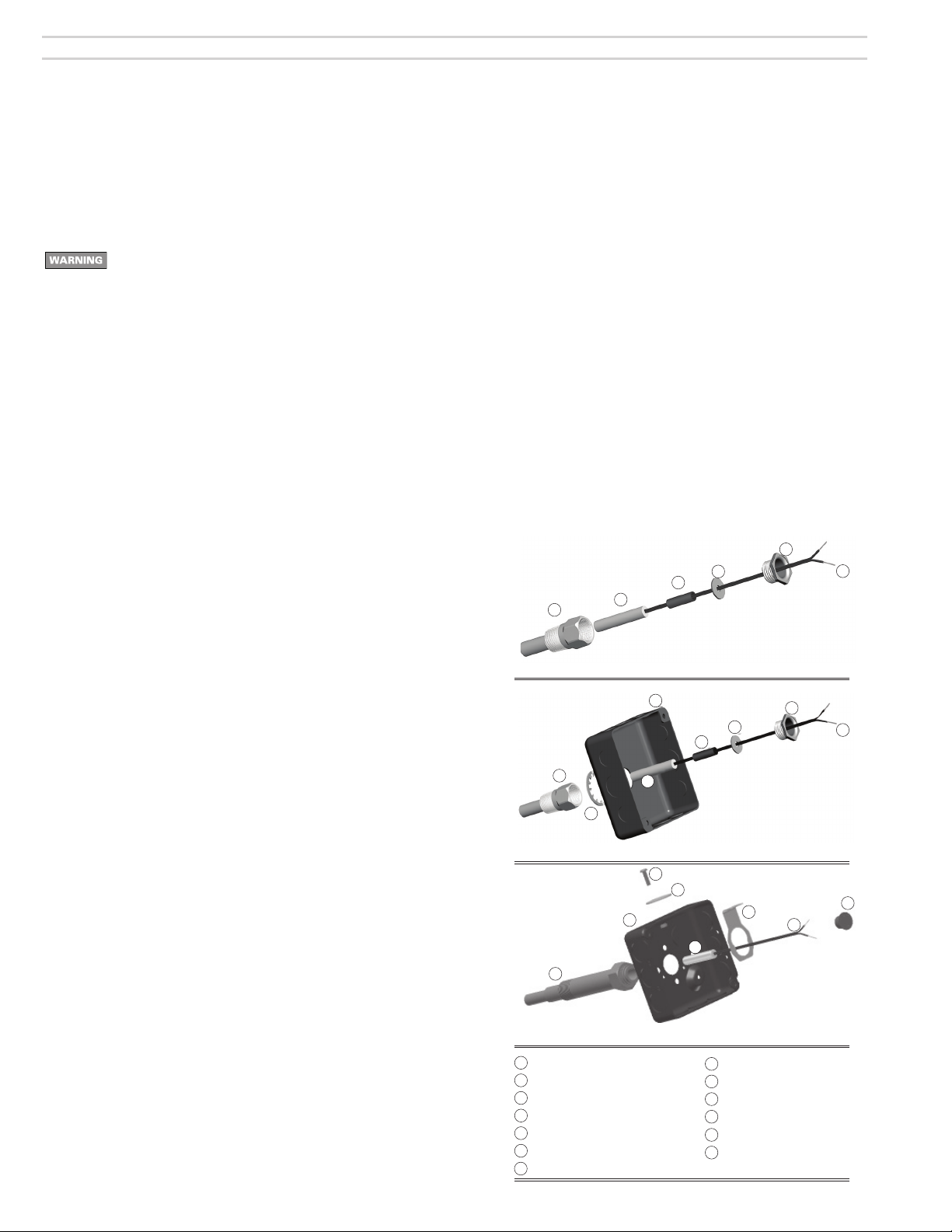
EZ-Temp well
EZ-Temp sensor
EPDM rubber retainer
Retainer washer
Jam nut
Sensor leads
J-box, 4 x 4
Lock washer
Existing well
Well clamp
Sensor retainer plug
12
13
12 Flat washer
13 Tensioning screw
A
High Limit Test Mode
“Hi-Test” mode (90000CE ONLY), used to test “High Limit Reset” at operating
boiler temperature. Start test with system operational and calling for heat. Turn
setpoint full clockwise to Hi-Test position. Green LED flashes fast. The setpoint
now adjusts both the high and operating limits. Turn setpoint slowly counter
clockwise until Lockout occurs. Now the setpoint temperature equals the hi-limit
sensor temperature. Test is complete, adjust setpoint to the desired operating
limit. Remove from lockout.
Configurations
Carlin EZ-Temp components are available in the following configurations, allowing
use with existing wells in addition to EZ-Temp wells.
Surface-mount sensors are also available.
• Control kits
EZ-Temp controls mount to a standard 4x4 J-box or can be panel mounted.
Control kits include the control and sensor(s) (item 2) plus hardware needed
for mounting to an existing well (items 10 and 11). To obtain an EZ-Temp well
and hardware, obtain an EZ-Temp well kit, below.
• Well kits
EZ-Temp wells are available in the sizes shown below. Well kits include a
well (item 1), rubber sensor retainer (item 3), retainer washer (item 4), jam
nut (item 5), and J-box lock washer (item 8).
• Sensor Kits
Sensor kits include only the sensor (item 2). Sensors are available in single
and dual configurations (two sensors in the same assembly). For controls
that use multiple sensors, obtain separate sensor kits or a sensor kit and a
dual sensor.
Install sensor(s)
To install a new immersion well:
1. Turn off power to the appliance and close isolation valves.
2. Follow appliance instructions to drain the appliance so water line is below
the insertion tapping.
3. Remove existing well and sensor. Apply a small amount of pipe dope to the
new well and secure in tapping.
4. Insert EZ-Temp sensor into well and secure sensor in place as described in
the following.
5. Refill appliance with water, following appliance manual procedures.
When routing sensor wires, avoid sharp edges and use strain
relief bushings at penetrations to prevent movement or electrical
shorting of the sensor. Sensor wires are not low voltage, and must
be routed in conduit.
Configuration A: Sensor and well only
1. Insert the sensor into well (1) until the sensor (2) tip bottoms in the well
socket.
2. EZ-Temp well: Slide the rubber retainer (3) over the sensor wires until it
firmly contacts the sensor casing. Slide the retainer washer (4) and the jam
nut (5) over the wires. Thread the jam nut into the well until snug.
3. Existing well: Press the sensor retainer plug (11) into the well until it securely
holds the sensor wires, to prevent movement of the sensor.
Configuration B: Sensor, EZ-Temp well and J-box
1. Insert the sensor into well (1) until the sensor (2) tip bottoms in the well
socket.
2. Slide the rubber retainer (3) over the sensor wires until it firmly contacts the
sensor casing. Slide the retainer washer (4) over the wires.
3. Slide the lock washer (8), J-box (7), and jam nut (4) over the wires.
4. Thread the jam nut into the well and tighten to secure the J-box and sensor
in place.
Configuration C: Sensor, EZ-Temp well and J-box
1. Remove the center knock-out from one side of the J-box (7).
2. Position the well clamp (10) over the end of the well (9) (sensor not yet
installed) and slide the well clamp (10) toward the side of the J-box (9)
engaging the keyslot opening with the well undercut.
3. Position the flat washer (12) over the open knockout and install the tension-
ing screw (13) through the flat washer (12) and into the well clamp (10),
tighten.
4. Insert the sensor into well (9) until the sensor (2) tip bottoms in the well
socket.
5. Press the sensor retainer plug (11) into the well until it securely holds the
sensor wires, to prevent movement of the sensor.
Mount the control
1. Insert sensor wire terminals into the labelled openings on the back of the
control. Press into place firmly.
2. Attach the control to the 4x4 J-box or panel mount, as desired.
Wire the control
1. Control wiring (including sensor wires) must be routed through conduit
or electrical enclosures. Follow all applicable codes and the appliance
manual.
2. Follow the burner and appliance wiring diagrams to connect the control(s)
into the appliance limit circuit.
3. For specific applications, contact your Carlin supplier for further informa-
tion.
Set the control
1. Follow the appliance manual to set the correct limit temperature for the
appliance. To adjust the EZ-Temp control:
• Insert a screwdriver into the setting slot and rotate until the indicator points
to the desired temperature.
2. Test the operation of the appliance and the new limit control(s) to verify
correct operation.
3. NOTE: EZ-Temp controls have a subtractive differential — control contacts
trigger when the temperature setting is reached. Contacts reset after tem-
perature drops below setpoint minus the differential amount.