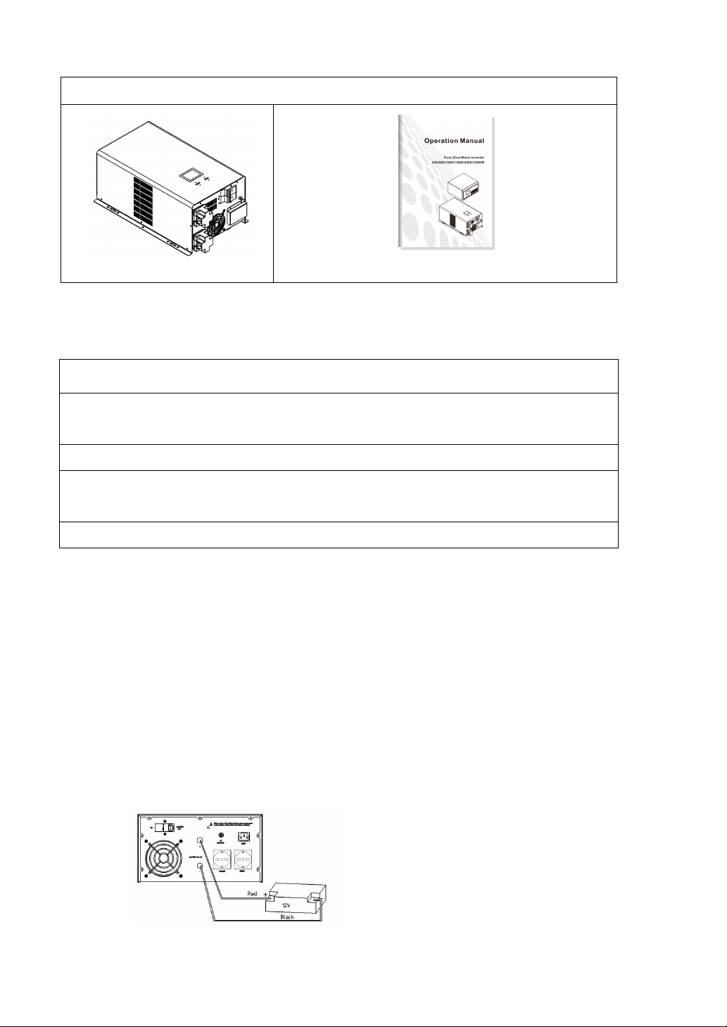
(Note that the red cable is connected to the positive terminal, black cable is connected to
the negative terminal)
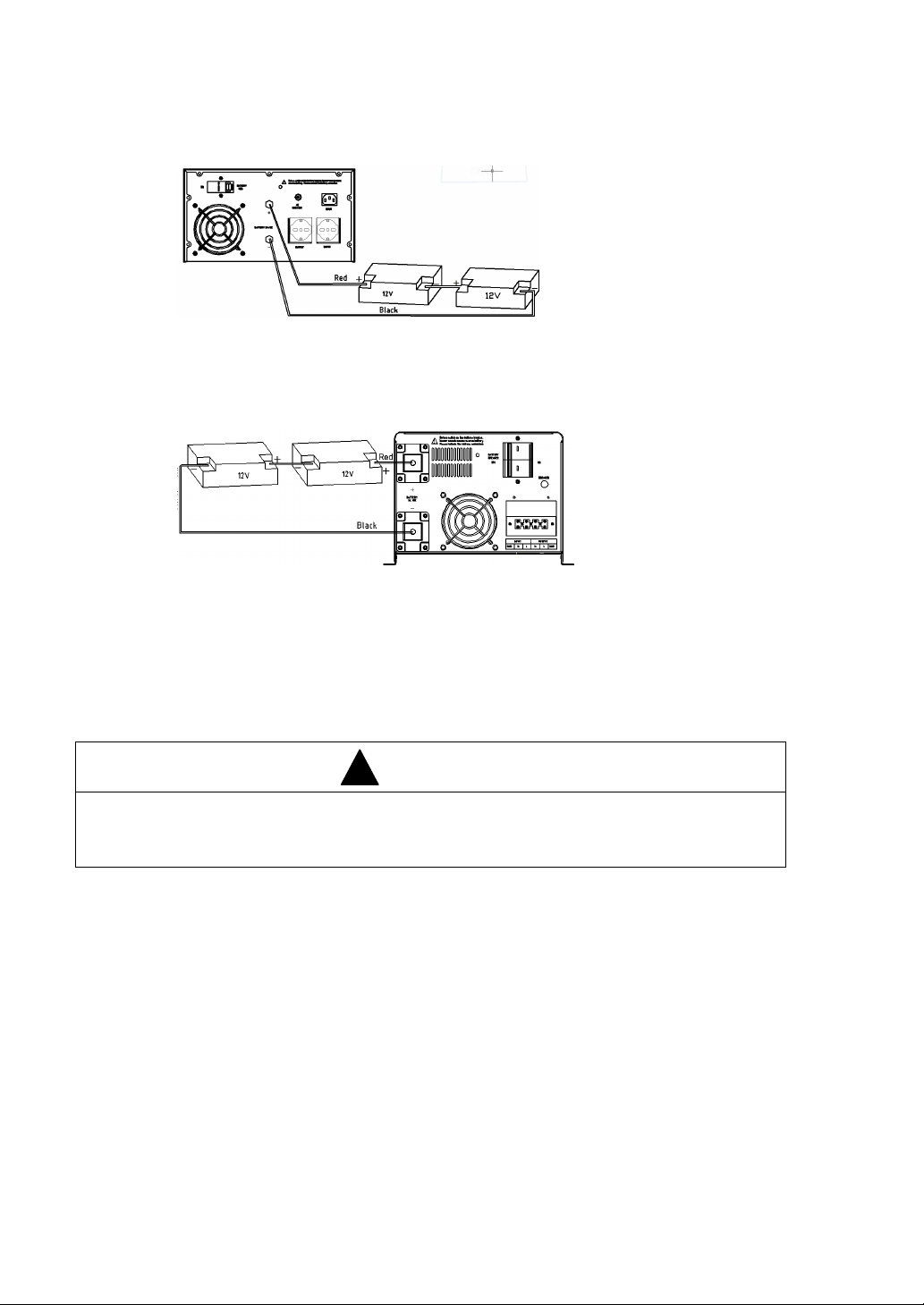
1600W DC24V inverter battery connection diagram
(Note that the red cable is connected to the positive terminal, black cable is connected to
the negative terminal)
2500W / 3500W DC24V inverter battery connection diagram
(Note that the red cable is connected to the positive terminal, black cable is connected to
the negative terminal, and 2500W battery cable is more than 35mm2, 3500W battery cable
is more than 50mm2)
4 Operations
CAUTION
Turn on the inverter in battery mode first. Be sure that the load has no problem
(overload, short-circuit ect.) before connecting to utility power.
4.1 Turn the inverter On/Off
Without connecting to utility power, press and hold “ON” button for 3
seconds, release it until the buzzer beeps, the inverter starts up. In the
process of the inverter running, press and hold “OFF” button for 3 seconds,
release it until the buzzer beeps, the inverter is shut down.
When the inverter works in mains power / AC mode, press and hold “OFF”
button for 3 seconds, release it until the buzzer beeps, the inverter goes to
bypass mode.
When the inverter works in bypass mode, press and hold “ON” button for 3
seconds, release it until the buzzer beeps, the inverter goes to AC mode.